
Related Manuals for UIrobot UIM240XX Series


Summary of Contents for UIrobot UIM240XX Series
- Page 1 User Manual UIM240XX Series Parallel Signal Control Miniature Integrated Stepper Motor Driver V1.2...
- Page 2 • UIROBOT will only work with the customer who respects the Intellectual Property (IP) protection. • Attempts to break UIROBOT’s IP protection feature may be a violation of the local Copyright Acts. If such acts lead to unauthorized access to UIROBOT’s IP work, UIROBOT has a right to sue for relief under that Act.
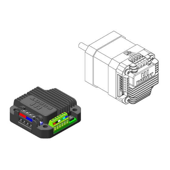
- Page 3 UIM240XX Miniature Integrated Stepper Motor UIM24002/24004/24008 Parallel Signal Control Miniature Integrated Stepper Motor Driver FEATURES Miniature size 42.3mm*42.3mm*16.5mm Integral design Wide range input voltage 12-28VDC 0 - 2A / 1.5 - 4A / 3 - 8A adjustable output current ...
-
Page 4: Terminal Description
UIM24002/04/08 TERMINAL DESCRIPTION Figure 0-1: Wiring Terminal Current Adjusting Trimmer DIP Switch2 Current Measurement Pads DIP Switch1 Motor Terminal To avoid loss of screws, please always keep screws tightened. Control Terminal Control Terminals Terminal No. Designator Description Supply voltage, 12 - 40VDC Supply voltage ground Opto-coupler common anode Direction input... - Page 5 UIM240XX Miniature Integrated Stepper Motor Attention: If no special instructions, users use UIROBOT controllers must strictly follow the specification that one controller can only drive one motor. Be careful to avoid connecting more than one motor to the controller. The user should be responsible for the loss caused by that error operation, our company will be not responsible for it.
-
Page 6: Typical Application
UIM24002/04/08 TYPICAL APPLICATION UIM240xx controller’s wiring is very straightforward as shown in following Figure. Terminal 6 (EN) can be left open if offline is not needed. Figure 0-2: Typical Application Stepper Motor 12 ~ 40VDC UIM240XX 3.3~5V 499 User MCU Direction Pulse Enable... - Page 7 UIM240XX Miniature Integrated Stepper Motor CHARACTERISTICS (†) Absolute Maximum Ratings Supply Voltage......................... 10V to 40V Ambient temperature under bias……………..............-40° C to +85° C Storage temperature......................-50° C to +150° C †NOTICE: Stresses above those listed under “Absolute Maximum Ratings” may cause permanent damage to the device. This is a stress rating only and functional operation of the device at those or any other conditions above those indicated in the operation listings of this specification is not implied.
-
Page 8: Functional Description
UIM24002/04/08 FUNCTIONAL DESCRIPTION Supply Voltage UIM240xx controllers accept a wide range input voltage from 12 to 40VDC. (UIM240L02 takes 12 – 28 VDC) In general, higher supply voltage improves motor performance under high speed situation, but also increases the power loss and temperature raise. Automatic Current Reduction (ACR) UIM240XX controller is featured of Auto Current Reduction. - Page 9 UIM240XX Miniature Integrated Stepper Motor Full 1/16 Resolution DIP Switch Actuator DIP Switch For ACR use APPENDIX A DIMENSIONS Units: mm UI Robot Technology Co. Ltd. M4020161125EN M40160606EN Page9...
- Page 10 UIM24002/04/08 APPENDIX B INSTALLATION NEMA 17 Stepper Installation (without adapting flange) Screw mount UIM controller / driver onto the motor Wire the motor leads. NEMA 23 and Larger Stepper Installation (with adapting flange) Screw mount the adapting flange onto the motor Screw mount UIM controller / driver onto the adapting flange Wire the motor leads.
Need help?
Do you have a question about the UIM240XX Series and is the answer not in the manual?
Questions and answers