
Related Manuals for UIrobot UIM2501


Summary of Contents for UIrobot UIM2501
- Page 1 r Ma M2501 RS23 3 2-CAN N2.0B Conv erting g Cont roller for U UIM24 2XX M Motion n Cont roller ...
- Page 2 • UIROBOT will only work with the customer who respects the Intellectual Property (IP) protection. • Attempts to break UIROBOT’s IP protection feature may be a violation of the local Copyright Acts. If such acts lead to unauthorized access to UIROBOT’s IP work, UIROBOT has a right to sue for relief under that Act.
-
Page 3: Description
RS232 interface on the user side and a CAN bus interface on the motor side (factory side). With the UIM2501, user will be benefited from the advantages of the CAN network and the simplicity of RS232 protocol, and no need to deal with the complicated CAN protocol, no worry about the communication distance and noise immunity. -
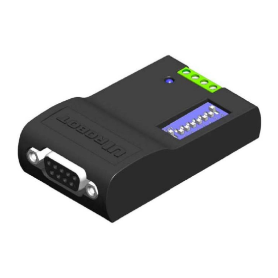
Page 4: Terminal Description
RS232 Connector is a DB-9 (Female Pin) connector. DIP Switch UIM2501 controller has an 8-bit DIP switch, which serves multiple functions. When powering up, DIP1~DIP7 are read as the UIM2501 controller’s ID/address. After powering up, DIP1 and DIP2 are assigned to other RS232 related features (refer to the “RS232 communication” section). -
Page 5: Typical Application
For long distance transfer, both ends of the bus should be terminated with120Ω terminating resistors. UIM2501 converter already has a build-in terminating resistor. To enable it, user needs toggle the DIP8 to the ON position. On the UIM242 controller side, user needs to attach a resistor to the end of the bus as shown in above figure 0-3. - Page 6 120Ω resistors. A star configuration should never be used. UIM2501 converter has a build-in terminal resistor. To enable the UIM2501 converter’s terminating resistor, please toggle the DIP8 to ON position. User only needs to attach a resistor at the UIM242 end of the bus.
-
Page 7: Characteristics
UIM2501 Converting Controller Characteristics (†) Absolute Maximum Ratings Supply Voltage......................... 6V to 40V Voltage on RX with respect to GND ................-25V to +25V Voltage on TX with respect to GND................. -13.2V to +13.2V Ambient temperature under bias……………............... -20°C to +85°C Storage temperature.................... -
Page 8: Table Of Contents
UIM2501 Table of Contents Description .......................... 3 Terminal Description ......................4 Typical Application ......................5 Characteristics ........................7 1.0 Overview ........................ 9 Instruction and Feedback Structure ..................9 Motor Control Functions and Instructions ................9 2.0 RS232 Communication ..................10 ... -
Page 9: Overview
Coordinates and controls UIM242 controllers in the network. With the UIM2501, user will be benefited from the advantages of the CAN network and the simplicity of RS232 protocol, and no need to deal with the complicated CAN protocol, no worry about the communication distance and noise immunity. -
Page 10: Rs232 Communication
Chapter, along with the method to reset the baud rate to factory default. Settings for User Device RS232 Port To communicate with UIM2501, user device needs to have following RS232 port settings: 8 bits data 1 stop bit... -
Page 11: Baud Rate Change Instruction(Bdr
UIM2501 Converting Controller Baud Rate Change Instruction(BDR) Any out-of-box UIM2501 controller has a factory default baud rate 9600. User can use the 9600 baud rate to connect to a new UIM2501 controller. To change to a different baud rate, user can use the instruction BDR as described below. -
Page 12: Standalone And Networking Operation
The process of ID assignment is described in section 3.2. Global Control Introduction Besides the object specific operation, UIM2501 can also send commands to all subsidiary UIM242XX controllers. This process is called broadcasting or global control instruction. 3.1.1 Global Instruction Format Global control instructions have the same format as shown below: a leading “g”... -
Page 13: Controller Id Assignment Instruction(Setadr
UIM242XX controller’s non-volatile memory. Object Specify Instruction(ADR) To operate a specific UIM242xx controller, user needs to first notify the UIM2501 controller which UIM242 controller is suppose to receive instructions. Therefore, before sending motor control instructions, user needs to use the following instruction to specify the UIM242xx controller’s ID. -
Page 14: Global Register Instruction (Greg)
0xCC. ) A1~A8 are the first 8 IDs found. Ax=0 means not found. Once this instruction is executed by the UIM2501 Controller, the total number of Comment all subsidiary UIM242xx controllers and their ID are recorded in the UIM2501 controller. -
Page 15: Global Motor Current Setup Instruction (Gcur)
UIM2501 Converting Controller Global Motor Current Setup Instruction (gCUR) Instruction gCUR Function Setup motor current for all subsidiary UIM242 Controllers Syntax Variable Integer x = 0、1 … 80 gCUR = x; 0xAA [QTY] 0xAD 0xFF Global Auto Current Reduction Instruction (gACR) -
Page 16: Global Position Control Instruction (Gstp)
UIM2501 3.12 Global Position Control Instruction (gSTP) Instruction gSTP Function Setup relative position control for all subsidiary UIM242 Controllers Syntax Variable Integer x = 0、1 … 2,000,000,000 gSTP = x; 0xAA [QTY] 0xAD 0xFF 3.13 Global Origin Point Setup Instruction (gORG) -
Page 17: Appendix A Dimensions
UIM2501 Converting Controller Appendix A Dimensions Mounting 2‐M3 depth 5 单位:mm Page | 17 M25020101008EN UI Robot Technology Co. LTD ...
Need help?
Do you have a question about the UIM2501 and is the answer not in the manual?
Questions and answers