
Related Manuals for Malvern Mastersizer Series


Summary of Contents for Malvern Mastersizer Series
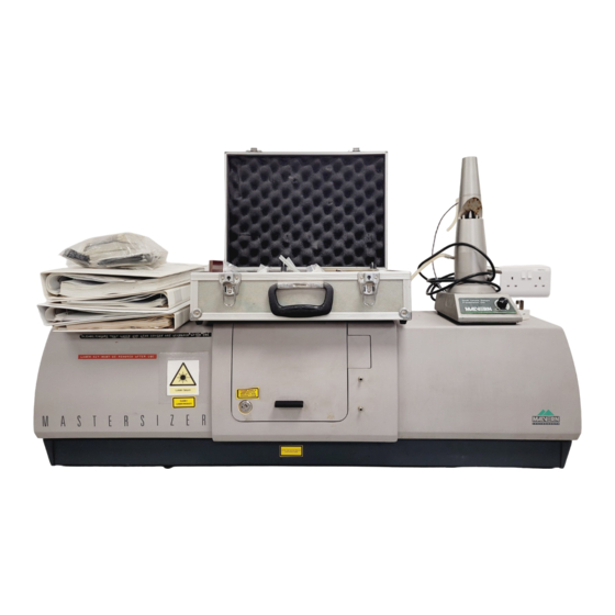
- Page 1 Getting Started Getting Started M A N 0 1 0 1 I s s u e 1 . 3 A u g u s t 1 9 9 7...
- Page 2 © Malvern Instruments Ltd. 1995, 1997. Malvern Instruments makes every effort to ensure that this document is correct. However, due to Malvern Instruments policy of continual product development we are unable to guarantee the accuracy of this, or any other document after the date of publication. We therefore disclaim all liability for any changes, errors or omissions after the date of publication.
-
Page 3: Table Of Contents
A typical system The optical unit The transmitter The sample area The receiver Differences between the long and standard bench Mastersizers 2-9 The Malvern software 2-10 The Mastersizer program group 2-10 Finding your way around the screen 2-11 Modes of operation... - Page 4 C O N T E N T S G e t t i n g S t a r t e d On-line help 2-16 The F1 Function key 2-17 The Help menu 2-17 The Help window 2-17 Jumps and Popups 2-18 Status line 2-19...
- Page 5 4-13 Chapter 5 - Analysing the measurement data Introduction Choosing the correct analysis mode Choosing the correct presentation The Malvern presentation grid Methods of selecting a presentation When is the presentation important? Selecting a presentation Special Presentations Calculating the result...
- Page 6 C O N T E N T S G e t t i n g S t a r t e d The Graph fonts The Table fonts Installing and selecting a printer Changing print settings Printing from the Mastersizer Chapter 7 - Interpreting the results Introduction Fundamental concepts...
- Page 7 C O N T E N T S Samples with unstable concentrations Bubbles Summary of sample preparation Chapter 10 - Advanced result processing Modifying results 10-1 Killing channels 10-1 Killing data channels 10-1 Killing result channels 10-3 Using the Kill cursors 10-4 Shape correction - Changing the size calibration 10-4...
- Page 8 C O N T E N T S G e t t i n g S t a r t e d Particle sizing specification Optical unit specification Computer requirements (minimum) Mastersizer programme specification Software Revision Level Appendix B - Chemical compatibility Introduction Components in contact with sample and dispersant Wet sample measurements...
- Page 9 C O N T E N T S Appendix F - Malvern addresses Malvern subsidiaries Appendix G - EMC performance Statement of EMC performance Statement of EMC performance for the Mastersizer S Equipment under test Test conditions EMC performance Statement of EMC performance for the Mastersizer X...
- Page 10 C O N T E N T S G e t t i n g S t a r t e d P a g e v i i i M A N 0 1 0 1...
- Page 11 Introduction to this manual Introduction to this manual...
-
Page 13: Welcome
This manual is designed to give a brief overview of what the Mastersizer can do and how to do it. Obviously, all the features of the Malvern Mastersizer can not be given within this manual. More detailed information is given in other manuals, such as the Software Reference manual. -
Page 14: Access To The Instrument
Below is a list of these people and their responsibility: Malvern personnel Malvern personnel (service engineers, representatives etc.) have full access to the instrument and are authorized to perform all service procedures that may require the removal of the transmitter and receiver covers. -
Page 15: Assumed Information
C H A P T E R 1 Assumed information For clarity this manual will assume that you have a standard bench Mastersizer S. If there are any operational procedures that differ for the long bench Mastersizer S or the Mastersizer X then alternative information will be given. Most samples measured on the Mastersizer are those dispersed in a liquid. - Page 16 C H A P T E R 1 Press or Select - This means click the mouse over a control or use the accelerator key (the underlined letter) or use the Tab key to move the focus to a control then use the Enter key. Menu items can be selected using the cursor keys in the same way.
-
Page 17: Menu Commands
If you have used a Malvern particle analyser before you may wish to go straight to chapters 4 and 5 where you can find practical information on making a measurement and analysing the data. - Page 18 Chapter 5 - Analysing the measurement data. This chapter will show you how to take the raw measurement data and analyse it, using the Malvern software, to get a final result. Advice is given on the choice of optical model and the presentation.
-
Page 19: Other Reading
C H A P T E R 1 Other reading More detail on the subjects within this manual can be found in the following manuals: Title Ref. number The Malvern Software reference manual. MAN 0102 The Malvern BASIC reference manual. MAN 0103 Health and safety. MAN 0104 P a g e 1 . - Page 20 C H A P T E R 1 P a g e 1 . 8 M A N 0 1 0 1...
-
Page 21: Chapter 2 - Getting To Know Your System
Getting to know your system Getting to know your system... -
Page 23: Introduction
The sole purpose of the sample preparation accessory is to prepare the sample and then deliver it to the optical unit so that it can be measured. Malvern makes P a g e 2 . 1 G E T T I N G... -
Page 24: The Optical Unit
The computer system is a stand alone computer that runs the Malvern software. It is the Malvern software that analyses the raw data from the optical unit to give the size of the particles. Once completed the result can be further analysed or reports printed etc. - Page 25 C H A P T E R 2 F U S E 1 0 0 V 2 6 0 V À “LV out” connector Connector that carries the low voltage power supply to the receiver. Á Power input socket Main power input socket to the optical unit. Â...
-
Page 26: The Sample Area
If your company operates within the pharmaceutical industry, you will be pleased to know that the Qspec sticker means that the instrument is eligible for coverage by a Malvern QSpec Validation contract which can help you to meet the requirements of the Food and Drug Administration (FDA). For further details contact your local Malvern Distributor. - Page 27 C H A P T E R 2 À Sample area cover Protective cover over the sample area. Designed to protect the operator from laser radiation and to keep the amount of background light to a minimum during a measurement. Warning! The sample area coremoved for spray measurements.
- Page 28 The sample to be measured is passed through the analyser beam by propelling the sample through a cell. Malvern make various forms of cell to cope with different types of material. One exception to using a cell is the case of spray measurements where an aerosol is sprayed directly though the analyser beam.
-
Page 29: The Receiver
C H A P T E R 2 Warning! Always replace the accessory panels after the accessory has been removed. Never run the system with the panels and accessory removed. Æ Back scatter connector Mastersizer S only. The 300RF range lens has a back scatter detector which is connected to the back scatter connector on the receiver bulkhead. - Page 30 G e t t i n g S t a r t e d C H A P T E R 2 Caution: The detector is the most delicate (and expensive) component of the system. In normal use the detector is safely contained within the covers of the receiver unit.
-
Page 31: Differences Between The Long And Standard Bench Mastersizers
(the 1000mm lens). When the 1000mm lens is used it is mounted in the additional sample area. All other functions and features are the same as the standard bench. The following section gives an overview of the Malvern software. P a g e 2 . 9 G E T T I N G... -
Page 32: The Malvern Software
C H A P T E R 2 The Malvern software The Malvern software controls all the functions of the optical unit during a measurement and then uses the data collected to calculate the result. The software is Windows based, requiring version 3.1 or greater and has been... -
Page 33: Finding Your Way Around The Screen
The main features are: À Title bar (or Caption) This shows the name of the program (Malvern Mastersizer) and, among other things, tells you the name of the current sample file. Á Menu bar The menu bar contains the main menu headings for all Mastersizer functions. - Page 34 G e t t i n g S t a r t e d C H A P T E R 2 key and press the letter which is underlined in the item required. For example to use the Measure menu hold down and press m.
- Page 35 C H A P T E R 2 A - Setup B - Open Sample File C - Document D - Align Optics E - Measure Background F - Inspect Result G - Calculate Result H - Save Record I - Print J - Setup Sequence K - Start Sequence L - Clear Graph...
- Page 36 G e t t i n g S t a r t e d C H A P T E R 2 Ã Table pane The table pane is used to show the result information in tabular form. Other information relevant to the measurement will also be shown. The type of information displayed in the table pane is determined by the “view”.
-
Page 37: Modes Of Operation
The instrument status bar will also show the progress of a measurement. Modes of operation The Malvern software has three main modes of operation, Easy, Menu and program mode, which are summarised below. Menu mode Menu mode is the use of the menu bar and its options to control the Mastersizer. -
Page 38: Program Mode
The Malvern basic language is an advanced feature that is usually used by the more experienced user. The full details of programming in the Malvern Basic language are given in the Malvern Basic manual. -
Page 39: The F1 Function Key
C H A P T E R 2 system. Almost all the software reference manual is available on the Help system and in some cases is easier to search than the manual. The F1 Function key You can get help on using the Mastersizer software at any point by pressing the F1 function key. -
Page 40: Jumps And Popups
G e t t i n g S t a r t e d C H A P T E R 2 you may find it useful to make the help window always stay on top of the Mastersizer window. To set the Help window to be always on top: . -
Page 41: Status Line
If there is a problem in the software try to give information that will allow the engineers at Malvern to reproduce the conditions. If the problem is in the result or the analysis the Malvern engineers will require a copy of the Data report. - Page 42 G e t t i n g S t a r t e d C H A P T E R 2 P a g e 2 . 2 0 M A N 0 1 0 1...
-
Page 43: Chapter 3 - How The Mastersizer Works
How the Mastersizer works How the Mastersizer works... -
Page 45: Introduction
C H A P T E R 3 Introduction After reading this chapter you will have a basic idea of the operating procedures of the Mastersizer and in particular: . Know the basic operating principles of the Mastersizer. . Know the simple steps involved in making a measurement and analysing the data. -
Page 46: How Does The Mastersizer Do It
2mS. . Secondly, once the measurement is complete the raw data contained in the measurement can be analysed by the Malvern software using one of the theories above. The measurement data is analysed by first selecting a “presentation”. A presentation is a predicted scattering pattern from theoretical particles. - Page 47 C H A P T E R 3 The presentation data is then made to fit the measurement data - this will give you the final size distribution. Once the data has been analysed the information can be displayed in various ways. Usually the display will show you a graph of the result and a table showing the same information in a tabular form.
-
Page 48: How To Make A Measurement
4. Setup for the measurement The Malvern software will need to know some of the physical parameters of the system, i.e. which lens is fitted or the type of sample preparation accessory is attached. - Page 49 C H A P T E R 3 Document the measurement It is always good practice to document your measurement so that you will be able to identify what was measured and how it was measured. A short sample identifier and notes can be saved with the measurement. Measure the background The scattering pattern from your sample is contaminated by light scattered by impurities within the dispersant, on the windows and lenses and also...
-
Page 50: How To Analyse The Measurement Data
G e t t i n g S t a r t e d C H A P T E R 3 It is usual at this point to go on and analyse the measurement but it can be saved on the computer so that it can be analysed at a later date if you wish. How to analyse the measurement data There are three steps required to analyse the measurement data: . -
Page 51: Calculating The Result
(imaginary refractive index) and the refractive index of the medium that the particle is suspended in (dispersant). Once the Malvern software knows this information it can calculate the expected scattering pattern from these particles. This scattering pattern is known as the “presentation”. -
Page 52: Viewing The Result
G e t t i n g S t a r t e d C H A P T E R 3 is shown on the screen by the “Residual”. The residual is an indication of how closely the calculated data has been fitted to the measurement data and is expressed as a percentage. - Page 53 C H A P T E R 3 Sample file: Monday.SAM Record Number Run Number " As can be seen, the run number is reset after each batch of 3 samples. So, for example, to see the data for the second sample taken two hours into Monday, you will open record number 5 from the MONDAY.SAM sample file.
- Page 54 G e t t i n g S t a r t e d C H A P T E R 3 P a g e 3 . 1 0 M A N 0 1 0 1...
-
Page 55: Chapter 4 - Making A Measurement
Making a measurement Making a measurement... -
Page 57: Introduction
C H A P T E R 4 Introduction It is usual for the operator to use the software to setup a “sequence” that, once set up, will automatically go through the procedures of measuring the sample, analysing the data and saving the results by simply pressing a single button. However, it is important to know the individual stages that are involved. -
Page 58: Sample Preparation
G e t t i n g S t a r t e d C H A P T E R 4 Sample preparation Firstly the most important thing to consider is the preparation of your sample before it is measured. A representative sample must be taken. Dry powders, for example, tend to separate out if stored for some time or vibrated. -
Page 59: Choosing A Range Lens
C H A P T E R 4 Choosing a range lens The Mastersizer has several range lenses available. For this initial measurement you will be using the 300RF lens on the Mastersizer S or the 45mm lens on the Mastersizer X. - Page 60 G e t t i n g S t a r t e d C H A P T E R 4 10.0 100.0 1000.0 Particle Diameter (µm.) The graph shows that the distribution is cut off at the large size end. Clearly there is a significant amount of material at sizes above 900µm.
-
Page 61: Sample Dispersion Method
C H A P T E R 4 Sample dispersion method The second thing to consider when choosing a lens is the way the sample is dispersed. Because of the physical arrangement of the 45mm and 300RF lenses it is not possible to measure samples dispersed in air (i.e. using one of the dry powder feeder accessories or performing spray measurements) using these lenses. -
Page 62: Always Measure A Background
G e t t i n g S t a r t e d C H A P T E R 4 The lens cut off point is only an issue when using the Mastersizer for spray measurements. Other forms of measurement use a cell to confine the samples within the measurement zone. - Page 63 C H A P T E R 4 . The flow cell is fitted and the pipes are connected to the dispersion unit ac- cording to the instructions in the Automated Sample Dispersion Unit man- ual. Before you begin a measurement you will have to tell the computer about the physical features that you have just set up, i.e.
-
Page 64: Document The Measurement
The Malvern software has a document dialogue that allows you to enter a name for the sample and enter details that will allow you to recreate the measurement in the future - such as how much sample you added, what dispersant you used, the pump speed etc. - Page 65 C H A P T E R 4 The ease of use of the Malvern software is demonstrated with these windows. It is of course possible to perform each of these tasks individually by first selecting Align from the Measure menu, aligning the system, then closing down the align window and then opening the next window, etc.
-
Page 66: Align The System
G e t t i n g S t a r t e d C H A P T E R 4 The live display shows the scattering pattern that is detected by the detector. As stated earlier, the detector is actually made up of series of photo diodes, arranged in a radial structure. -
Page 67: Take A Background Measurement
C H A P T E R 4 onds to complete, but if the system is badly out of alignment it may take up to two minutes. When aligned the laser power reading should show a value greater than 75. Take a background measurement A background measurement is taken to measure the background electrical noise and the laser scattering from contaminants on the optics and within the dispersant. - Page 68 G e t t i n g S t a r t e d C H A P T E R 4 The system measures whether the concentration is suitable by monitoring the “obscuration” of the beam caused by the sample being added to the dispersant. The obscuration is simply the fraction of light “lost”...
-
Page 69: Measure The Sample
C H A P T E R 4 N O T E If you are not in the Measure-background dialogue you can select the Measure-inspect dialogue by selecting Inspect from the Measure menu or alternatively you can select the Inspect button. . - Page 70 G e t t i n g S t a r t e d C H A P T E R 4 N O T E If you are not in the Measure-Inspect dialogue then you can select the Measure-Sample dialogue by selecting Sample from the Measure menu.
- Page 71 Analysing the Analysing the measurement data measurement data...
-
Page 73: Introduction
C H A P T E R 5 Introduction This chapter describes the analysis of the measurement data. There are three steps involved; choosing the analysis mode, choosing a “presentation” and finally telling the software to calculate the result. It should be remembered that the measurement data is never changed during the analysis. - Page 74 C H A P T E R 5 The choice of which model to use is very simple - unless you definitely know that the result graph will be of a particular shape always use the polydisperse model. So, when will you use the other modes? The multimodal model assumes that there are a few distinct sizes of particles within the sample.
-
Page 75: Choosing The Correct Presentation
The Malvern presentation grid The Malvern presentation grid is a convenient method of labeling presentations. The presentation is labeled by a four character code of the form “3OHD”. The presentation grid is shown on the next page - refer to this grid when reading the next section, which which discuses its contents. - Page 76 C H A P T E R 5 chosen to give the widest choice of popular values. There are many reference books available that state the refractive indices of materials. Instrument First Relative Second Relative Third Dispersant Fourth character particle character refractive character...
-
Page 77: Methods Of Selecting A Presentation
In very rare circumstances you may find that the choice of presentation is critical to the results and the values on the Malvern presentation grid are not accurate enough. In this situation a presentation can be generated that use the exact figures for the refractive index etc. -
Page 78: When Is The Presentation Important
. Use a presentation that is the closest match from the existing presentations. . Calculate a new presentation based on the values within the Malvern pres- entation grid. . Calculate a new presentation based on the exact values entered. -
Page 79: Selecting A Presentation
1 micron then the presentation is important. . If the ratio of the refractive indices is under 1.1 or the size of the particles is under 1 micron then the presentation is critical. Contact Malvern for an ap- propriate model matrix. -
Page 80: Special Presentations
Fraunhofer scattering theory. A special presentation, 3$$1, is provided for use with the Malvern Diffraction Reference Reticle. Contact your Malvern Instruments representative, or see the Reticle manual, for more information. - Page 81 C H A P T E R 5 To calculate the result . Select Calculate Result from the Measure menu. The Calculate Result dialogue box will appear. This dialogue is shown below. The Calculate Result dialogue shows the progress of the analysis by displaying the residual.
- Page 82 C H A P T E R 5 P a g e 5 . 1 0 M A N 0 1 0 1...
- Page 83 Viewing and printing the results Viewing and printing the results...
-
Page 85: Introduction
The data can be displayed in various formats - each format is known as a view. Malvern provides 11 standard views that can be quickly selected by opening the View menu. The View menu is shown below. - Page 86 G e t t i n g S t a r t e d C H A P T E R 6 N o t e : It should be noted that the result data is never changed - it is only displayed in a different way.
-
Page 87: Reports
Reports Each of the standard views that is provided by Malvern has a corresponding print report that will allow you to print the data within the view. Each report is designed to suit A4 size paper. The report contains the same information as in the table and graph panes except that up to 4 lines of sample documentation are also included in the report. -
Page 88: Overview Of The Standard Views And Reports
If you are an advanced user you can also customise the report to display the information to suit you own needs using the Mastersizer Basic language. See the Malvern Basic Reference manual (MAN 0103) for more information. To print a report . - Page 89 C H A P T E R 6 not require your data to be presented in a format that can be compared to sieve measurements then you will never use the three standard views on sieve standards. The following section gives an overview of the views available. Take time to read through the section - you should be able to quickly identify the views that are not applicable to your type of analysis.
-
Page 90: Understanding Printing
G e t t i n g S t a r t e d C H A P T E R 6 Understanding printing This section goes into more detail on the subject of printing. If you are reading this manual for the first time you may feel that the information within this section will not be beneficial at this point. -
Page 91: Selecting Fonts For Graphs And Tables
C H A P T E R 6 applications, such as the Mastersizer software, will become less responsive to the keyboard and mouse. If you have sufficient memory installed you might consider installing a ramdrive. The Print Manager is able to use this area of memory for temporary spooling instead of writing files to the hard disc. -
Page 92: Installing And Selecting A Printer
Note that the font size will have an effect on the size of the table. All the tables provided by Malvern use a line spacing set by the font in use. If the font size is increased the table will increase in length and may not fit on the screen or the printed page. -
Page 93: Changing Print Settings
C H A P T E R 6 . Select the Setup... button. A dialogue box is produced that allows printer options to be changed. Refer to the Help system by selecting the Help but- ton on this dialogue. Pay particular attention to the resolution setting. If you have installed more than one printer make the one you will use most of the time the default. - Page 94 G e t t i n g S t a r t e d C H A P T E R 6 From this you can select the content of the print. A Report is a single page summary of the result as a table of values, a graph and a summary of measurement conditions and sample details.
- Page 95 Interpreting the results Interpreting the results...
-
Page 97: Introduction
C H A P T E R 7 Introduction This chapter sets out to give you guide-lines on the interpretation of the results that the Mastersizer generates. The first section explains some important concepts that you have to understand before proceeding. The second section runs through some of the terms and expressions that are used in the standard views. -
Page 98: Equivalent Spheres
100.0 1000.010000.0 Particle Diameter (µm.) The Malvern software allows the result to be converted to other distribution forms such as a number distribution for example, but it should be remembered that the initial measurement is volume based and any subsequent conversions are liable to introduce systematic errors. -
Page 99: Derived Distribution Parameters
C H A P T E R 7 . Equivalent surface area. You can calculate the diameter of a theoretical sphere that has the same surface area of the original particle. . Equivalent maximum length. This is where the diameter of a theoretical sphere is the same as the maximum dimension of the original particle. -
Page 100: Understanding The Tables And Graphs
G e t t i n g S t a r t e d C H A P T E R 7 The same principle of calculation applies to the distribution statistics standard deviation, skewness and kurtosis. For “mono-size” distributions such as latex the distribution mean is reported as the geometric mean of the size class and standard deviation, skewness and kurtosis are reported as zero. - Page 101 C H A P T E R 7 The undersize curve À takes the form of “the percentage below a certain size” for example 20% (reading the figures from the right hand scale) of the sample is under 40 microns etc. The oversize curve Á...
- Page 102 G e t t i n g S t a r t e d C H A P T E R 7 used the correct presentation. Try re-analysing the measurement data with a new presentation. Á The statistics of the distribution are calculated from the results using the derived diameters D[m,n] - an internationally agreed method of defining the mean and other moments of particle size.
- Page 103 C H A P T E R 7 É SSA (Specific Surface Area) The specific surface area is defined as the total area of the particles divided by the total weight. If you are using this value then it is important to set the density of the sample from the Setup-Analysis dialogue.
- Page 104 G e t t i n g S t a r t e d C H A P T E R 7 P a g e 7 . 8 M A N 0 1 0 1...
- Page 105 Automating the process Automating the process...
-
Page 107: Introduction
C H A P T E R 8 Introduction The manual so far has taken you through the individual steps of making a measurement and processing the data. This has allowed you to understand the individual processes involved. In practice however you would most probably set up the whole measurement sequence as a semi-automatic process. - Page 108 C H A P T E R 8 G e t t i n g S t a r t e d The options within this dialogue allow you to analyse the measurement data (using the analysis model and presentation currently selected in the Setup - Analysis and Setup - Presentation menu items) and save the results for each measurement that the sequence makes.
- Page 109 C H A P T E R 8 Click No if you want to stop the sequence. If a delay has been set between cycles of the sequence and the time of the measurement is less than the delay time then a window appears to count down the remaining time.
- Page 110 C H A P T E R 8 G e t t i n g S t a r t e d P a g e 8 . 4 M A N 0 1 0 1...
- Page 111 Sample preparation Sample preparation...
-
Page 113: Introduction
C H A P T E R 9 Introduction Now that you have successfully made a measurement and analysed the result, we shall return to the important subject of sample preparation. The preparation of the sample before it is added to the system can be critical. Over half the problems encountered when measuring a sample are caused by bad sample preparation. -
Page 114: Considerations For Dry Samples
C H A P T E R 9 G e t t i n g S t a r t e d As the bottle vibrates in transit Á, large particles part to allow fine particles to fall through  and then close together over the fine particles - being lifted in the process. -
Page 115: Considerations For Wet Samples
C H A P T E R 9 measurement. Obviously care should be taken with delicate materials where drying in the oven may damage the sample. A fresh sample that has not had time to absorb moisture from the atmosphere is always preferable and will usually give better results. - Page 116 C H A P T E R 9 G e t t i n g S t a r t e d tank will be suitable. Filter this water prior to use. Another solution is to warm the dispersant (for water typically to 60 - 80 C) and then allow to cool before use.
-
Page 117: Surfactants And Admixtures
C H A P T E R 9 Surfactants and admixtures If you are experiencing problems such as the sample floating on the surface of the dispersant then the addition of a surfactant or an admixture may be helpful. The next section briefly explains the use of these additives. -
Page 118: Admixtures
C H A P T E R 9 G e t t i n g S t a r t e d Admixtures Admixtures also aid dispersion by modifying the properties of the dispersant itself that are responsible for the problem. Admixtures are added in larger quantities, typically 1g/l. -
Page 119: Samples With Unstable Concentrations
C H A P T E R 9 ultrasonics by placing the slurry and its beaker into an ultrasonic bath. It will be apparent if this has been effective. Further ultrasonics can be applied when the sample is added to the tank, if necessary. This will often prevent re-agglomeration, but is not always necessary. -
Page 120: Summary Of Sample Preparation
C H A P T E R 9 G e t t i n g S t a r t e d Bubbles can be tested for by circulating the dispersant with appropriate additives through the cell using the dispersion unit, and turning on the ultrasonics. Should bubbles pass through the cell and scatter light then you have a problem. - Page 121 Advanced result processing Advanced result processing...
-
Page 123: Modifying Results
C H A P T E R 1 0 Modifying results The result produced by the analysis may be modified in a number of ways before it is presented in the graph or table. The modifications are controlled from the Setup-Result Modifications dialogue. - Page 124 G e t t i n g S t a r t e d C H A P T E R 1 0 It is important to realise that if these parameters are set unnecessarily the accuracy and resolution of the analysis will be reduced. Do not set kill channels at the lower end of the range to exclude data routinely unless you have good reason.
-
Page 125: Killing Result Channels
C H A P T E R 1 0 1000. 10.0 Particle Diameter (µm.) 1000. 10.0 Particle Diameter (µm.) The data channels may be killed by either using the Setup-Analysis dialogue or by adding kill cursors to the data graph, as shown below. Both of these methods create a new result with the channels killed. -
Page 126: Using The Kill Cursors
G e t t i n g S t a r t e d C H A P T E R 1 0 Using the Kill cursors The kill cursors are produced by depressing the left mouse button with the cursor in the left or right margin of the graph and then dragging the mouse towards the centre of the graph. - Page 127 C H A P T E R 1 0 The Shape Correction works by modifying the size boundaries of each measurement class, which are originally defined by scattering theory and the geometry of the optics and detector. The action of the shape correction is to change these size values - in effect changing the calibration of the Mastersizer.
-
Page 128: Extending The Result
G e t t i n g S t a r t e d C H A P T E R 1 0 Slope = A1 Slope = A2 d' µm d µm The shape correction factors are stored as a shape file. The shape file can be created and edited using the Edit-Shape Factors dialogue. -
Page 129: Transforming Result Type
C H A P T E R 1 0 . At least one result within the range of the Mastersizer. The Mastersizer re- sult will be scaled to be the percentage below the smallest of these sizes. The lower end of the Mastersizer may also be extended by entering manually a value in the smallest size band of the Mastersizer in place of the value calculated from the analysis. -
Page 130: Blending Results
G e t t i n g S t a r t e d C H A P T E R 1 0 10.0 100.0 1000.010000.0 Particle Diameter (µm.) The example above shows the result of transforming a skewed volume distribution À... -
Page 131: Multiple Modifications
For more information on Tromp analysis ask your Malvern representative for the paper “The Importance of Particle Size in the Cement Industry” by Dr Alan Rawle. - Page 132 G e t t i n g S t a r t e d C H A P T E R 1 0 P a g e 1 0 . 1 0 M A N 0 1 0 1...
- Page 133 Maintenance Maintenance...
-
Page 135: Introduction
The Mastersizer has been designed so that supervisor/operator maintenance is kept to a minimum. It should be fully understood that no one, except a qualified Malvern representative, should remove the transmitter or receiver covers of the instrument. The supervisor should only remove the sample area cover if spray measurements are to be performed and should only do so after reading the Health and Safety manual and the instruction manual for the spray accessories. -
Page 136: Replacing Fuses
Internal diameter - 3/16". External diameter - 5/16". Flexible - to allow the cell to be removed without having to remove the pipes. ® The tubing originally supplied by Malvern is Tygon R-3603 available from ® ® Cole-Parmer Instrument Company. Tygon is chemically compatible with a large range of materials. -
Page 137: Cleaning The Covers
C H A P T E R 1 1 replacing simply pull the fuse out of its holder and replace with the appropriate fuse from the list below. The fuse required is: CSA applications (USA, Canada etc). 240V/110V, 1.25" 5A AS UL/CSA Rest of the world. -
Page 138: Cleaning The Optics
G e t t i n g S t a r t e d C H A P T E R 1 1 Cleaning the optics The Mastersizer is a precision optical device. Cleanliness of the optics are fundamental to ensuring good measurements. It will occasionally be required to clean the cell windows, range lenses and the beam expander. - Page 139 Inspect both sides of the cell window. If there are any signs of scratches the windows should be replaced. Spare windows may be obtained through your Malvern representative. At this point any dust on the surfaces of the window can be removed using a compressed gas duster can.
-
Page 140: Cleaning The Range Lenses
G e t t i n g S t a r t e d C H A P T E R 1 1 If this does not eliminate the mark then consider the use of a liquid cleaner such as Ethanol Absolute or Propan-2-ol. This can be soaked on a cotton wool bud and wiped across the window gently. -
Page 141: Cleaning The Beam Expander
C H A P T E R 1 1 Caution! Never remove the lens from the lens holder. The lens is precisely set at manufacture. Store the lens with lens caps on to avoid the need to repeat this procedure often. Cleaning the beam expander The beam expander will not require cleaning as often as the range lenses. - Page 142 Failure to align the aperture plate in the exact original position will result in “clipping” of the laser. This will require a visit from one of Malvern’s qualified service engineers or representative to rectify. The user should on no account attempt to re-align the aperture plate.
- Page 143 C H A P T E R 1 1 P a g e 1 1 . 9 G E T T I N G S T A R T E D...
- Page 144 Specification Specification...
-
Page 146: Introduction
A P P E N D I X A Introduction This specification covers the Mastersizer in its most basic form i.e. without any details of the sampling accessories. Details on the specification of the accessories can be found in their individual accessory manuals. This specification covers both the Mastersizer X and Mastersizer S - any information that is specific to a particular model is given separately. -
Page 147: Optical Unit Specification
A P P E N D I X A G e t t i n g S t a r t e d Scattering angle 0.01 - 135 degrees (over the 3 ranges of Mastersizer S). range. 0.03-50 degrees (over the 3 ranges of Mastersizer X ). 0.01-50 degrees (over the 4 ranges of long bench Mastersizer X). - Page 148 A P P E N D I X A Receiver for the Fourier transform lens mount. Mastersizer S. Range lenses of 300RF (reverse Fourier), 300mm and 1000mm (1000mm for long bench Mastersizer only). Composite detector array measuring a large angle range and two back scatter detectors in the 300RF range lens assembly.
-
Page 149: Computer Requirements (Minimum
A P P E N D I X A G e t t i n g S t a r t e d Detector 48, (31 for the Mastersizer X) amplifier parallel sample/hold construction, electronics. A/D conversion and on board digital storage. µ... -
Page 150: Mastersizer Programme Specification
Presentation generator. The Malvern instruments warranty over the computer configuration only extends to those supplied by Malvern Instruments. Users should be aware that not all hardware sold as Microsoft Windows compatible is fully so. If you wish to operate your own configuration it should be fully tested before purchase. -
Page 151: Software Revision Level
There is an extensive on-line help system available. Software Revision Level Malvern is engaged in a continuing programme of development, both in measurement capabilities and software features. Thus, during the lifetime of a product a number of software versions will exist, in general increasing in capability as they become more current. - Page 152 Chemical compatibility Chemical compatibility...
-
Page 154: Introduction
A P P E N D I X B Introduction The Mastersizer and its accessories have be manufactured from materials that are considered to give the widest protection from chemical attack. However, it is important to check that any sample or dispersant you may use is chemically compatible with the materials that they will come in contact with the system. -
Page 155: Spray Measurements
A P P E N D I X B G e t t i n g S t a r t e d Spray measurements Component Location Materials Sample area Internal surfaces. Glass (lenses). Anodised aluminum. Two-pack polyester paint. Stainless steel. All spray measurements should be extracted to the outside of the building. -
Page 156: Appendix C - Remote Interlock Remote Interlock
Remote interlock Remote interlock... - Page 158 A P P E N D I X C Remote interlock The Mastersizer does not require an external interlock switch to comply with CDRH or EC laser safety regulations. However, some company safety regulations may require the room in which the Mastersizer is installed to be protected so that if the door to the room is opened then the laser in the optical unit is disabled.
- Page 159 A P P E N D I X C G e t t i n g S t a r t e d N o t e The second switch must be of the “spring return” type that will automatically return the switch to the open position when the switch is released.
- Page 160 Estimating the absorption Estimating the absorption...
-
Page 162: Introduction
A P P E N D I X D Introduction When choosing the presentation for an analysis you will be required to enter a value for the imaginary refractive index (this is effectively the absorption) of the sample you are measuring. This can be difficult as the value has to be calculated by performing an experiment. - Page 163 G e t t i n g S t a r t e d A P P E N D I X D As an example consider the measurements shown below. A sample of material was suspended in water at a volume concentration of 0.032 The differential refractive index is low and the size around 1µm so that presentation is important.
- Page 164 Advice for continuous sprays Advice for continuous sprays...
-
Page 166: Introduction
Introduction The measurement of a continuous stable spray is the simplest that can be made with your instrument, requiring no essential extra accessories. Malvern offer an Aerosol Mounting Unit which you may find useful for repeatably positioning the nozzles and directing the spray. -
Page 167: Don't Spray The Optical Unit
A P P E N D I X E G e t t i n g S t a r t e d ligaments that will later divide into stable droplets. Thus the limiting minimum distance may not be set by concentration considerations alone. In other sprays the droplets themselves may be volatile and evaporate rapidly causing size distributions that will change with distance from the nozzle. - Page 168 Malvern addresses Malvern addresses...
-
Page 170: Malvern Subsidiaries
A P P E N D I X F Malvern subsidiaries If you purchased your Malvern Mastersizer from an agent for Malvern Instruments Ltd. products please contact them for servicing and sales information. If you purchased your Malvern Mastersizer from Malvern Instruments direct please use the following information to contact us. - Page 171 G e t t i n g S t a r t e d A P P E N D I X F Malvern Instruments (Asia Pacific) 38 Jalan Bangkung Bukit Bandaraya 59100 Kuala Lumpur Malaysia Tel: +60 (0) 3 252 1973...
- Page 172 Regulatory compliance Regulatory compliance statements statements...
-
Page 174: Statement Of Emc Performance For The Mastersizer S
Directive 72/23/EEC the Low-Voltage Directive as amended by Directive 93/68/EEC the CE Marking Directive. The directive has been satisfied for Malvern equipment by applying BS EN 61010-1 :1993 Safety requirements for electrical equipment for measurement, control, and laboratory use Part 1 - General requirements. -
Page 175: Emc Performance
A P P E N D I X G G e t t i n g S t a r t e d During emission tests the equipment was under control of a Mastersizer S Version 2.11 Software Automated Sequence. This repeatedly measured a known sample. -
Page 176: Statement Of Emc Performance For The Mastersizer
A P P E N D I X G Statement of EMC performance for the Mastersizer X The CE-badge on this product signifies conformance with the protection requirements of the European EMC directive, (89/336/EEC). The following statement of EMC performance refers to the Mastersizer X system as defined below operating under the following test conditions. - Page 177 A P P E N D I X G G e t t i n g S t a r t e d . Complies with BS EN55022 (1995), class B, radiated and conducted emis- sions. . Complies with BS EN50082-2 (1995), generic immunity standard (indus- trial environments).
- Page 178 Index Index...
- Page 180 I N D E X Print Abort connector Setup sequence Access to the instrument Start/stop Malvern personnel Operator Calculating the result Supervisor Cells Accessory panels Adding the sample 4-11 Flow Admixtures Pipe connectors Align button 4-10 Stirred Alignment 3-4, 4-10...
- Page 181 Cleaning the range lenses 11-6 Graphs Fuses 11-2 Replacing the sample tubing 11-1 Hardware setup Malvern personnel Help 2-16 Malvern presentation grid F1 Function key 2-17 Mastersizer program group 2-10 Help jump cursor 2-19 Bitmap Editor 2-10 Help menu 2-17...
- Page 182 I N D E X Easy mode 2-15 Printing Menu mode 2-15 Graph 6-10 Program mode 2-16 Installing a printer Modifying results 10-1 Print button Blending results 10-8 Report 6-10 Extending the result 10-6 Table 6-10 Kill cursors 10-4 Understanding printing Killing channels 10-1 Window...
- Page 183 I N D E X G e t t i n g S t a r t e d Removable accessory panels Tables Sample area cover Theory Sample cell Derived distribution Sample area cover parameters Sample cell Equivalent spheres Sample file Fraunhofer Sample preparation 4-2, 9-1...
Need help?
Do you have a question about the Mastersizer Series and is the answer not in the manual?
Questions and answers