Table of Contents
Advertisement
Quick Links
Advertisement
Table of Contents

Related Manuals for Malvern Mastersizer 3000


Summary of Contents for Malvern Mastersizer 3000
- Page 1 MASTERSIZER 3000 PARTICLE SIZE USER MANUAL...
- Page 3 Mastersizer 3000 User Manual MAN0474 Issue 2.1 August 2013...
- Page 4 United Kingdom. Tel + [44] (0)1684-892456 Fax + [44] (0)1684-892789 Mastersizer, Malvern and the 'hills' logo are registered trademarks in the UK and/or other countries, and are owned by Malvern Instruments Ltd. Windows is a registered trademark of Microsoft Corporation.
-
Page 5: Table Of Contents
Where to get help Introducing the Mastersizer 3000 ..........2-1 Introduction . -
Page 6: Table Of Contents
Table of Contents Viewing measurement results ..........5-1 Introduction . -
Page 7: About This Manual
The instrument measures the size of particles contained within a sample, presenting data according to the user’s needs. This user manual is a companion to the Mastersizer 3000 Basic Guide, which gives Health and Safety, maintenance, troubleshooting and other vital information which all users must read. -
Page 8: Access To The Instrument
Warning! Removal of the covers by unauthorized personnel will invalidate the war- ranty of the instrument. Unless advised within the content of this manual, only Malvern Instruments trained personnel are permitted to remove the main cover of any part. Supervisor The supervisor is the person responsible for the management and safety of the instrument and its operation. -
Page 9: Assumed Information
To make full use of this manual, the user should understand the following points. Naming convention Within this manual: The Mastersizer 3000 and 3000E instruments will be referred to as “the optical unit” or “the instrument”, or simply the Mastersizer. -
Page 10: Where To Get Help
Chapter 1 Introduction to this manual The SOP Player feature, shown above, is only available with the Mastersizer 3000 / Mastersizer3000E with Extended software option. Where to get help This section describes the available sources of information on the system. The pri- mary sources of information on the system are instrument and accessory manuals and the software’s help system. -
Page 11: Technical Support
If you do not have internet access from the computer operating the Mastersizer system, contact your local Malvern Instruments repre- sentative - details of all local telephone numbers are available at www.malvern.com. Always quote the following information: Model and serial number of the instrument. The serial number is shown ... - Page 12 Chapter 1 Introduction to this manual Remote support Malvern Instruments offers a remote support service, delivered by an internet con- nection. Benefits include fast and efficient fault diagnosis, as well as reducing downtime and costs. Malvern website - www.malvern.com The Malvern Instruments website offers a comprehensive range of particle charac- terisation resources for use by customers 24 hours a day, seven days a week.
- Page 13 Mastersizer 3000 and Mastersizer 3000E instruments There are two core instruments in the Mastersizer 3000 family, these are the Mas- tersizer 3000 and Mastersizer 3000E. Though identical looking there are some fun- damental differences between the two; in terms of their software functionality and operation with the associated dispersion units.
- Page 14 Chapter 2 Introducing the Mastersizer 3000 Hardware Particle size range 0.1 - 1000μm 0.1 - 1000μm 0.01 - 3500μm Compatible with Manual • • • Hydro wet dispersion units (Hydro EV / SM) Compatible with Auto- • • mated Hydro wet disper-...
- Page 15 Mastersizer (or “the optical unit” or “the instrument”), unless it is necessary to differentiate or highlight any differences; then the instrument will be identified as Mastersizer 3000 or 3000E as appropriate. Mastersizer 3000 Page 2-3...
-
Page 16: About The Mastersizer
Chapter 2 Introducing the Mastersizer 3000 About the Mastersizer The Mastersizer is comprised of the main optical unit, one or more dispersion units and a measurement cell. Commonly, a dispersant such as de-ionised water is also connected directly to the dispersion unit. -
Page 17: Typical Systems
Introducing the Mastersizer 3000 Chapter 2 Typical systems Wet dispersion A wet system consists of the optical unit and either the Hydro LV/MV or EV dis- persion unit. These dispersion units are designed to circulate a liquid sample through the Mastersizer's measurement cell. Many materials need to be measured as wet dispersions. - Page 18 Chapter 2 Introducing the Mastersizer 3000 The following illustration shows a typical wet dispersion unit installation: ill 8620 Optical unit Wet cell Wet dispersion unit Computer running the Master- sizer application software Optical unit (as described in the next section) Measures the sample using red and blue light wavelengths.
- Page 19 Introducing the Mastersizer 3000 Chapter 2 Dry dispersion The Aero S dry dispersion unit is only compatible with the Mastersizer 3000 optical unit. A dry system comprises of the main optical unit plus the Aero S dispersion unit. The Aero S is designed for providing an even circulation of dry powder throughout Mastersizer measurement cell.
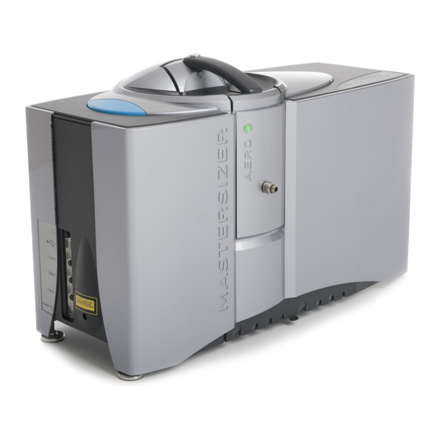
- Page 20 Chapter 2 Introducing the Mastersizer 3000 Optical unit (as described in the next section) Measures the sample using red light detection. Dry dispersion unit (in this case the Aero S) Disperses the sample and transports it to the measurement cell.
-
Page 21: Optical Unit Components
Introducing the Mastersizer 3000 Chapter 2 Optical unit components This diagram shows the optical unit, the main component of the Mastersizer system. The unit directs red and blue light through the sample and then collects the light scattered by the particles within the sample using a set of light-sensitive detec- tors. - Page 22 End panel Provides the communication connectors for the optical unit as well as the power connection and switch. Refer to the Mastersizer 3000 Basic guide for further connection reference. Protection window Stops dust/dirt entering the system. Clean this window periodically. Refer to the Mastersizer 3000 Basic guide for more information on cleaning the protection window.
-
Page 23: End Panel
Introducing the Mastersizer 3000 Chapter 2 End panel The end panel of the instrument provides the communications and power connec- tions. ill 8623 Power switch CAN 1-3 Power input Power switch Press once to power on the unit, press again to power off. - Page 24 Chapter 2 Introducing the Mastersizer 3000 Provides data communication with the PC. For best performance connect to a high speed USB port on the PC: CAN 1-3 Supplies power and data communication to the dispersion unit. Power input Input for 24V power supply unit.
-
Page 25: Cell Components
Introducing the Mastersizer 3000 Chapter 2 Cell components The following illustration shows the key parts of a wet cell – for a more detailed description of both the wet and dry cells, refer to the Hydro or Aero Dispersion Unit Guides respectively: ill 8625 ... - Page 26 Chapter 2 Introducing the Mastersizer 3000 Cell handle Only lift the cell by this handle. Sample output (blue) Connected to the sample in (blue) on the dispersion unit. Temperature regulator throughput Provides throughput connections to a water jacket within the cell. This allows an (optional) heater/chiller to regulate the sample temperature to help minimise the effect of ultrasound heating.
- Page 27 Introducing the Mastersizer 3000 Chapter 2 Note If the cell is raised and lowered too many times in a short period, the firm- ware will lock the cell in place for a period of time before it can be ejected again;...
- Page 28 Chapter 2 Introducing the Mastersizer 3000 Page 2-16 MAN 0474...
- Page 29 For information on how to run a measurement, see the Making measurements chapter. Some advanced features of the software are also detailed in the Supervisor’s section of this guide and reference information for all features is provided in the Help system. Mastersizer 3000 Page 3-1...
-
Page 30: Powering On And Starting The Software
Powering on and starting the software Ensure that the optical unit, dispersion unit and computer are connected (con- nection reference is given in the Mastersizer 3000 Basic guide). Power up the computer and printer (if available) by following the instructions in the manuals supplied. -
Page 31: Software User Interface
Lists all measurements within the active measurement file. Multiple measurement files can be opened simultaneously, which are then accessible by different tabs within the Record View. All files tab View all records from all open measurement files in a single tab. Mastersizer 3000 Page 3-3... - Page 32 Chapter 3 Software overview Reports tabs Provides access to reports on the currently selected record. The reports shown are a function of the currently selected workspace. Data Quality tab Provides guidance on the measurement quality and displays a simple pass/fail data report based on selected models, together with tips on how to improve the meas- urement.
- Page 33 The Record View allows you to view and edit the records contained in Master- sizer 3000 measurement files. It is also possible to open files that were created by Mastersizer 2000 instruments, but not edit them. Mastersizer measurement files consist of a number of individual measurement records. Mastersizer 3000 Page 3-5...
- Page 34 See the Viewing the measurement results chapter, and the Help file, for more information on grouping and filtering. The Parameter filters, grouping and column configuration features are only available with the Mastersizer 3000 / Mastersizer 3000E with Extended soft- ware option. Editing which parameters are displayed To choose different columns of data to display in the Record View: Right click on a column header and choose Column Configuration.
- Page 35 Alternatively the data export options can be used (refer to the Advanced features chapter). Reports tab Reports are displayed automatically whenever you select a record, or number of records, from the Record view (assuming that the selected view is showing the Reports tab). Mastersizer 3000 Page 3-7...
- Page 36 Reporting chapter Data quality tab The Data Quality tab is only available with the Mastersizer 3000 / Mastersizer 3000E with Extended software option. The Data quality tab presents a custom analysis of any records selected in the cur- rent measurement file.
- Page 37 Software overview Chapter 3 The above illustrates the Default data quality selection. Two additional checks are available; these are ISO variability and USP variability. Illustrations of each are shown below. Mastersizer 3000 Page 3-9...
- Page 38 Chapter 3 Software overview Workspaces Workspaces are only available with the Mastersizer 3000 / Mastersizer 3000E with Extended software option. This section describes the purpose of workspaces and the Workspace pane. Workspaces are a collection of settings that define the information presented in the Reports and Record View, as well as which folders the system uses for accessing SOPs, measurement data and export data.
- Page 39 Measurement files and SOPs within the workspace can be pinned to keep them in the windows indefinitely. To pin an item, hover the mouse over the item and select the pin button. Mastersizer 3000 Page 3-11...
- Page 40 Chapter 3 Software overview Record and reports view selector The record parameters shown in the Record View, and the reports listed in the Reports view are controlled using the Record and reports view selector to the right of the of the Workspace pane. Additionally the Records and report selector stores (and restores) any selected data quality addins.
- Page 41 C:\Users\YOURNAME\Documents\Malvern Instruments\Mastersizer 3000\Workspace\ If the Shared workspace is selected the folders stem from: C:\ProgramData\Malvern Instruments\Mastersizer 3000\Workspace\ Shortcuts Shortcuts are an easy mechanism for users to set-up a set up links to folders, e.g. on a network, that can be shared between all users on that PC.
-
Page 42: Customising The Software Interface
Note Some options are only available with a feature key installed. Please con- tact your Malvern representative for more information. From the Application button menu choose Options to display the Mas- tersizer 3000 - Options window. Then click the required link on the left to view its corresponding settings. - Page 43 Data processing - Analysis SOP and record edi- tor. The emulator converts Mastersizer 3000 results to how it would be analysed on a Mastersizer 2000 instruments, and similarly for a Mastersizer 3000E result the Mastersizer 2000E instruments is emulated.
- Page 44 Chapter 3 Software overview Themes The Themes option is only available with the Mastersizer 3000 / Mastersizer 3000E with Extended software option. Several themes are available which modify the colour settings of the user interface. Click Theme from the Options window and then select a scheme that suits your preference by clicking Use this theme.
- Page 45 Extended software features The same software is used to control both variants of the Mastersizer instruments - the Mastersizer 3000 and the Mastersizer 3000E, though some software features are removed for a 3000E installation. The Mastersizer 3000E software focuses on just the necessary software features for operating the instrument - this is termed the Basic feature set.
- Page 46 Consult the help system for a full description of each feature. 21 CFR Part 11 The 21 CFR Part 11 functionality is only available for Mastersizer 3000 users. Select this option and input the 21 CFR feature key when requested. With the 21...
- Page 47 The Predefined window layouts allow to you quickly select from a number of optimized panel arrangements within the Mastersizer user interface. From the Predefined window layouts group in the View ribbon, select the required layout. Mastersizer 3000 Page 3-19...
- Page 48 Chapter 3 Software overview Quick access toolbar The Quick access toolbar provides an alternative method for accessing commonly- used functions. To add any ribbon function button to the Quick access toolbar, right-click it and choose Add to Quick access toolbar. The button is now additionally displayed (in reduced form) in the title bar of the software: In this example, the Manual measurement, Save and 2-pane tabbed buttons have been added to the Quick Access toolbar.
-
Page 49: Maintenance Utilities
The Maintenance window gives access to various background information about the system that can be useful as part of an ongoing maintenance schedule or in the process of contact with the Malvern Instruments Help Desk. Choose Tools-Maintenance from the ribbon to display the Maintenance ... - Page 50 The main purpose of the system information area is to display details about the software, operating system and hardware connected. This information must be passed to the Malvern Instruments Helpdesk whenever you log a support call. To send this information to Malvern Instruments: If you have email software on the Mastersizer computer: Click Contact Malvern to display the contact form.
- Page 51 Notifications from: the date when users should start being prompted to carry out a task. Task due by: the date by which the task needs to be completed. Repeat interval: how often the task should be done (weekly, monthly, yearly, etc). Mastersizer 3000 Page 3-23...
- Page 52 Chapter 3 Software overview Task description: text providing guidance as to what needs to be done by the user. All users can complete task option: Select this checkbox to confirm that any user can complete the task. If this is left un-ticked then only users who have the Open Maintenance security permission assigned to them can set the task to done.
- Page 53 After 24 hours, if no further log files have been generated, only the last log file generated is retained. Log files contain no data that is of direct use to users, but may be requested by the Malvern Helpdesk when trying to resolve any issue. To send a log file: Click on the Save Text Report option on the maintenance report icon bar.
- Page 54 Chapter 3 Software overview Page 3-26 MAN 0474...
- Page 55 Manual measurements tend to be used for one-off measurements or as part of method development (i.e. establishing the optimal settings for measuring the sample and then saving into an SOP file). Mastersizer 3000 Page 4-1...
-
Page 56: Measurement Prerequisites
Chapter 4 Making measurements Standard Operating Procedure (SOP) measurements – most of the measurement settings are stored within an SOP file which has been previously created by the user. Once an SOP has been initiated, the measurement sequence requires less user intervention than a manual measurement. As SOPs lock-down most of the measurement settings they improve consist- ency and provide greater repeatability;... -
Page 57: Making Sop Measurements
SOPs can control the configuration of the optical unit and the sample dispersion unit, including the measurement parameters, timings, analysis models and other specific set-up information. They can also be configured to prompt the operator to perform specific tasks such as sample preparation steps. Mastersizer 3000 Page 4-3... - Page 58 Chapter 4 Making measurements The quality and value of an SOP depends on the quality of the method develop- ment work on which it is based. A series of manual measurements is required to establish the ideal parameters for use in an SOP. A number of standard SOP tem- plates have been prepared in advance for typical measurements, which may be used unchanged or as the basis for a new SOP.
- Page 59 Reference section in later in this Chapter. When all the required settings have been specified, you can either choose to save the SOP as a file or as a template. choose File-Save and then give the SOP a logical name. Mastersizer 3000 Page 4-5...
- Page 60 Chapter 4 Making measurements Running an SOP (Hydro units) If you are using a wet dispersion unit (the Hydro LV/MV/EV) work through the steps in the order given here. No manual control of the dispersion units is required after loading the sample; the software controls all settings. Select Run SOP from the Measurements section of the ribbon.
- Page 61 The Trend view show in the bottom half of the Measurement display illustra- tion is only available with the Mastersizer 3000 / Mastersizer 3000E with Extended software option.
- Page 62 separately or tiled next to each other by selecting the split view button. The split view button is only available with the Mastersizer 3000 / Mastersizer 3000E with Extended software option. Click the Start button to Initialise the instrument. If specified in the SOP settings, the system prompts the user to enter/confirm sample documen- tation details.
- Page 63 The results are now presented in the Record View. More about the Trend view The Trend view is only available with the Mastersizer 3000 / Mastersizer 3000E with Extended software option. The Trend view is a powerful analytical tool that shows record data in a graphical format as soon as it has been measured by the system.
- Page 64 Chapter 4 Making measurements can be added to the Trend view, for example to see how Ultrasound Power settings are affecting the measurement. By default, each measurement’s Dv10, Dv50 and Dv90 figure is shown, so it is very simple to make a quick assessment of the result. The Dv50 category shows the median particle size.
- Page 65 All numerical data then provided is the arithmetic mean of the currently selected records, with the exception of the initial particle size figure, which is still the figure for the single record. Mastersizer 3000 Page 4-11...
- Page 66 Chapter 4 Making measurements Adding further trend graphs Add additional plots using the following method (note that the new plot needs to be configured prior to making the measurement in order to display data): Right-click on the trend graph and select Add above or Add below to add a new plot.
- Page 67 Making measurements Chapter 4 Running an SOP (Aero units) The Aero S dry dispersion unit is only compatible with the Mastersizer 3000 optical unit. The software controls most of the dispersion unit settings except the hopper height, which is a manual adjustment. Work through the steps in the order given here.
- Page 68 Chapter 4 Making measurements Choose an appropriate SOP for the Aero dispersion unit (ensure also that the SOP is optimized for the venturi type that is fitted to your Aero unit - either stainless steel or ceramic venturi) and then click OK. The Measurement Display window shown below is displayed: Click Start –...
- Page 69 When all of the measurements have been made, the system pauses - optionally, click Clean System on the top progress bar to initiate a cleaning cycle. Complete the measurement by closing the SOP Measurement window. The results will now be presented in the Record View. Mastersizer 3000 Page 4-15...
-
Page 70: Making Manual Measurements
Chapter 4 Making measurements Making manual measurements In addition to SOP measurements, users can also make manual measurements. This may be useful, for instance, when investigating the most appropriate method for sample dispersion prior to setting up an SOP. This section provides details on how to run a basic manual measurement. - Page 71 Browse database - select the material if it is present to automatically add the RI and Absorption values to the measurement. Use the Measurement-Duration section, shown below, to set up measure- ment times for the red and blue measurements. Mastersizer 3000 Page 4-17...
- Page 72 See Controlling dispersion units (manual mode) later in this chapter for more information. The docked accessory control tab in the Measurement display is only availa- ble with the Mastersizer 3000 / Mastersizer 3000E with Extended software option. Users with the Basic software feature set should control the dispersion unit using the Accessories option on the Tools ribbon.
- Page 73 The Trend view is only available with the Mastersizer 3000 / Mastersizer 3000E with Extended software option. Continue this final Measure Sample process as many times as required by clicking Start again.
- Page 74 Manually controlling the dispersion units The docked accessory control tab in the Measurement display is only availa- ble with the Mastersizer 3000 / Mastersizer 3000E with Extended software option. Users with the Basic software feature set should control the dispersion unit using the Accessories option on the Tools ribbon.
-
Page 75: Manual Control Accessories
On the Home ribbon, select New-SOP from within the Documents group. ribbon. (To edit an existing SOP, choose Open-SOP instead.) Complete the SOP Editor as described in the Mastersizer 3000 User Manual. Information on the manually controlled accessories is described in the dispersions units respective user manual. -
Page 76: Sop Player
Chapter 4 Making measurements SOP Player The SOP Player is only available with the Mastersizer 3000 / Mastersizer 3000E with Extended software option. With SOPs created and saved, users are now able to define an SOP playlist sequence where results can be automatically collected for a single sample using dif- ferent measurement and/or analysis settings - this is done using the SOP player. - Page 77 Switches the view between icons or detail view In the above example: The SOP at the top of the playlist (Hydro LV - SOP 1) is used to initialize the Mastersizer system and request sample details. Mastersizer 3000 Page 4-23...
- Page 78 Chapter 4 Making measurements The final SOP in the list (Hydro LV - SOP 3) is used to control the clean sequence. The dispersion unit, measurement and analysis settings for each SOP in the list are applied in sequence when the playlist is run. SOP playlists can be opened and saved using the options at the top ...
-
Page 79: Measurement Settings Reference
The Sample Identification settings section allows you to enter details that will both identify the sample and provide more information to users. When the measure- ment is run, the user is prompted to confirm or alter the fields specified here. Mastersizer 3000 Page 4-25... - Page 80 Chapter 4 Making measurements Section/option Description Sample Name A descriptive name for the sample, such as "Batch 1A" or (mandatory) "Series 3, Sample 1". This is the only default sample identifi- cation field. Adding a Field To add further fields for example, Notes, Batch, Lot, Group etc., click the Add button.
- Page 81 Spherical This analysis mode is applicable for particles which are per- fectly spherical in shape. For example, it should be selected for polymer latex samples or for emulsions. Mastersizer 3000 Page 4-27...
- Page 82 Chapter 4 Making measurements Section/Option Description Spherical This mode uses Mie Theory, and therefore requires input of (continued) the optical properties of your sample in order to calculate a particle size distribution. The advantage of this is that it provides the possibility of obtaining accurate size distributions for all particle sizes.
- Page 83 If required, select the check box and add the Refractive light properties index (blue-light) and Absorption index (blue-light). See (Wet dispersion Help System for more information. units only) References and Any further comments that help to describe the material. notes Mastersizer 3000 Page 4-29...
- Page 84 Chapter 4 Making measurements Sample - Dispersant This is a unique window for Wet dispersion SOPs. Use the Sample Dispersant section settings to specify the properties of the dis- persant used in the measurement. It is possible to specify the dispersant details manually or to choose from the Dis- persants Database.
- Page 85 References and Enter any further comments that help to describe the disper- notes sant. If the newly added dispersant will be used in the future, add it to the Dispersants Database by clicking Add to database. Mastersizer 3000 Page 4-31...
- Page 86 Chapter 4 Making measurements Sample - Instructions Use the Sample Instructions settings to specify pre-measurement and post- measurement instructions that need to be drawn to the attention of the user. These are then shown in the Sample Documentation panel/window before and fol- lowing the measurement respectively.
- Page 87 Mastersizer 3000 Page 4-33...
- Page 88 Chapter 4 Making measurements Section/option Description Blue measure- Blue light measurement is more effective when measuring ment duration(s) particles under approximately 1μm in size. There is a gradual reduction in the effectiveness (and hence significance to the (Wet dispersion overall measurement result) of the use of blue light on sam- units only) ples containing particles above this size.
- Page 89 5, allows repeatability to be assessed. In wet measurements a Pre-measurement delay (s) can be specified. This delay occurs before the very first measure- ment but after Ultrasound has been stopped, assuming the pre-measurement ultrasound option is selected. Mastersizer 3000 Page 4-35...
- Page 90 Chapter 4 Making measurements Measurement - Obscuration The Measurement Obscuration settings enable you to specify the obscuration lev- els between which the measurement will be conducted. This is critical for ensuring the correct amount of sample is added to the measurement system. The optimal obscuration settings for a measurement are both sample and disper- sion unit dependent.
- Page 91 These are described in the dispersions units respective user manual. Hydro series wet dispersion units manual for the Hydro MV, LV, EV and SM dispersion units Aero series dry dispersion units manual for the Aero dispersion units Mastersizer 3000 Page 4-37...
- Page 92 Chapter 4 Making measurements Sample Dispersion - Cleaning The Cleaning options allow you to specify both a clean sequence and whether to use ultrasound as part of the sequence. This ensures that all traces of the sample just measured are removed so that no contamination of the next sample occurs. Cleaning following a measurement is essential to ensure that background noise, consisting of particles agglomerating within the system and forming accumula- tions, is minimized.
- Page 93 Note: It is preferable that all dispersants are degassed before being added to the system. Degas by storing the dis- persant at room temperature and pressure before use. Mastersizer 3000 Page 4-39...
- Page 94 Chapter 4 Making measurements Section/option Description Ultrasonication Ultrasound can reduce agglomeration, which may help fur- ther with cleaning. Select whether to Use ultrasound during (Wet dispersion the clean sequence or No ultrasound during clean. units only) Air pressure Use the slider bar to set the air pressure at which any remaining sample is removed (from 0-4 bar, in 0.1 bar incre- (Dry dispersion ments).
- Page 95 To do this, use the Edit Result feature after the first set of measurements has been made – see Viewing the measurement chapter for more informa- tion. Mastersizer 3000 Page 4-41...
- Page 96 Mastersizer 2000 / 2000E analysis models are emulator mode added to the list. The emulator converts a Mastersizer 3000/3000E results to how it would be analysed on a Mastersier 2000/2000E instruments, The extra analysis modes are: General Purpose (Emulated MS2000 / MS2000E) –...
- Page 97 This option should be enabled for samples containing a sig- Mode nificant proportion of material below 10 microns in size. It can help improve the result reproducibility, and can be used (Dry dispersion with any of the Mastersizer 3000 analysis modes. units only) Advanced button Mastersizer 3000 Page 4-43...
- Page 98 X, and are used to help with method transfer from older Malvern laser diffraction systems: Selecting each lens range will truncate both the detector range and the size range of the Mastersizer 3000 system to match the selected system. Select this feature for use from the options menu...
- Page 99 Adjusting the low and high size range will alter the fit applied to the fundamental result, where the intermediate values are then read from the curve allowing interpolation of percentile points. This adjustment will not alter the analysis bands that are used in the measurement. Mastersizer 3000 Page 4-45...
- Page 100 Chapter 4 Making measurements Result range Note: The software will automatically flag the use of any (continued) range reduction facility to preserve the integrity and tracea- bility of the results. Result type Set the result type for the particle size distribution - choices are Volume distribution (recommended), Surface area dis- tribution or Number distribution.
- Page 101 Note: When the extended size band set overlaps the Master- sizer result, it is assumed that the extended result will be correct. Therefore the Mastersizer result will be truncated and renomalized to fit with the new extended result data set. Mastersizer 3000 Page 4-47...
- Page 102 Chapter 4 Making measurements Data Processing - User Sizes The Data Processing: User Sizes settings allow size banding for the measure- ment to be defined for all histograms and tables used in reports. Section/option Description User sizes A practical use of size bands is when using sieves that con- form to specific standard sizes - size bands could be set to corresponding ranges.
- Page 103 Use the sizes that I specify option described above and then load in the file containing the data for the sieve set required. Sieve sizes are available for all standard ASTM, BS, ISO and Tyler sieve sets. Mastersizer 3000 Page 4-49...
- Page 104 Chapter 4 Making measurements The ISO sieve size sets includes a list of the micron sizes for all of the available sieves; these sieves are in the same format as the standard Mastersizer size class files. The ASTM, BS and Tyler sieve size class files include a MESH reference for ...
- Page 105 To enable exporting select the Export data? check box. Custom/Default Select either the Default template or create a Custom one. template Note The Default template will reflect the current workspace set- tings and use the record view column configuration. Mastersizer 3000 Page 4-51...
- Page 106 Chapter 4 Making measurements Export settings Choose either rows or columns from the Ordering selector to present the data horizontally or vertically respec- tively. From the Delimiter selection, choose either Comma separated (csv) or Tab separated. Your choice will depend on the requirements of the target application. Use the Formatting option to select either Format values as displayed in software, which displays numeric information to a limited number of decimal places (this may...
- Page 107 The filename will be saved as a .txt or .csv file as determined by the delimiter selection. Destination The exported file will be saved in the Export Data folder of the current workspace. Mastersizer 3000 Page 4-53...
- Page 108 Chapter 4 Making measurements Output - Averaging An SOP can be set to run through a number of measurements, with an average result then being created at the end; as set by the Output - Averaging window. Section/option Description Averaging After the measurements have finished it may be advanta- geous to see the average value produced from all the meas- urements run.
- Page 109 This window contains a list of Available Reports on the left and Selected Reports on the right. Reports shown with are reports that were created by Malvern Instruments. Move reports from the Available Reports column to the Selected Reports column (and back as required) by select-...
- Page 110 Chapter 4 Making measurements Page 4-56 MAN 0474...
- Page 111 The Mastersizer delivers powerful features for manipulating and presenting the data gathered in measurement files. This chapter provides the following information: An overview on working with measurement files. Features of the Analysis report. Fundamental concepts to help understand measurement data. Mastersizer 3000 Page 5-1...
-
Page 112: Working With Measurement Files
This section provides information on how to open and close existing Mastersizer 3000 (.mmes files) and Mastersizer 2000 (.mea files). Files from the Mastersizer S/X/Micro/Microplus instruments can also be opened (.sam files). These first have to be saved to an Mastersizer 3000 measurement file format. However, no reanalysis is possible. Note Although Mastersizer 2000 files can be opened for analysis, they cannot be edited directly. - Page 113 Filtering the Record View The parameter filters feature is only available with the Mastersizer 3000 / Mastersizer 3000E with Extended software option. This section provides information on how to set up parameter filters within the Record View.
- Page 114 Chapter 5 Viewing measurement results Click the down arrow to display a list of available parameter values upon which to filter (these are the values shown in the record). Select any of the values to show only those records with values matching the checked filters.
- Page 115 Viewing measurement results Chapter 5 Column configuration The column configuration feature is only available with the Mastersizer 3000 / Mastersizer 3000E with Extended software option. The columns can be changed as required to indicate various parameters. Right click the mouse in the header field of the record view to display the Column configuration button, then select the button to display the Parameter selection window.
- Page 116 Parameter Selection window. Grouping records The grouping records feature is only available with the Mastersizer 3000 / Mastersizer 3000E with Extended software option. Read this section for details on how to group records by parameter type.
- Page 117 It is now possible to sort, group, filter and report on the records displayed in this view. If graphically analysing multiple records in reports, each record's data is overlaid using a different colour. Mastersizer 3000 Page 5-7...
- Page 118 Chapter 5 Viewing measurement results Creating an averaged record The Create Averaged Record feature allows you to create a new record that con- tains the average values of all selected records. From the Record View, select the records from which to create an average and choose Create average from the Home ribbon.
- Page 119 When the result has been edited, the edited result is then displayed as the last item in the record view (this is dependent upon the view configuration). Mastersizer 3000 Page 5-9...
- Page 120 Chapter 5 Viewing measurement results Note If you save the measurement file, the new settings will overwrite the origi- nal file settings. To create a result-edited version of a file and still retain the original file settings, just save the file with a different name before editing. Selecting records to display in a report Mastersizer reports display data from all measurement records that are currently selected in the Record view.
-
Page 121: Analysis Report
The following information is displayed in the report: Weighted Residual – an indication of how well the calculated data was fitted to the measurement data. A good fit is indicated by a residual of under 1%. A Mastersizer 3000 Page 5-11... - Page 122 Chapter 5 Viewing measurement results residual of over 1% may indicate use of incorrect refractive index and absorp- tion values for the sample and dispersant. The statistics of the distribution are calculated from the results using the derived diameters D[m,n] – an internationally agreed method of defining the mean and other moments of particle size.
- Page 123 If the SSA is used, it is important that the density of the material is defined (in the SOP’s Material settings). This figure is a mathematical calculation based on the assumption that the particles are both spherical and non-porous. Mastersizer 3000 Page 5-13...
-
Page 124: Fundamental Concepts
Chapter 5 Viewing measurement results Fundamental concepts To understand the meaning of the results from the Mastersizer, a number of fun- damental concepts require explanation. These are: How the concentration is calculated. The results are volume-based. The result is expressed in terms of equivalent spheres. ... - Page 125 diameter d - the mean extinction term for size-class i - is calculated from scattering the- ory and is a function of the optical properties of the particle and dispersant media. Mastersizer 3000 Page 5-15...
- Page 126 Chapter 5 Viewing measurement results Concentration at different obscurations This advice gives an approximate idea of the obscuration ranges to use during a measurement. It is possible to convert the obscuration limits into an equivalent volume concen- tration but there is a strong size dependence that makes it difficult to use the data at the time of measurement.
- Page 127 50 micron particles. What is required is a unique number that describes the particle. There is only one shape that can be described by one unique number and that is a sphere. If we say we have a sphere of Mastersizer 3000 Page 5-17...
- Page 128 Chapter 5 Viewing measurement results 50 microns, this describes it exactly. We cannot do the same even for a cube as 50 microns can refer to its edge or to a diagonal. One way to get a single unique number to describe an irregular shaped particle is to compare some feature of the actual particle to an imaginary spherical particle.
- Page 129 The same principle of calculation applies to the distribution statistics standard devi- ation, skewness and kurtosis, as shown below: standard deviation – --------------------------------- - Mastersizer 3000 Page 5-19...
- Page 130 Chapter 5 Viewing measurement results skewness – – 3 --------------------------------- - ----------------------------------------------------------------------- - Skew kurtosis – ...
-
Page 131: Optical Models
A standard set of materials is available for selection in the SOP (presented in the Sample - Material section of the measurement settings). Further materials can be defined by a user within the materials database, but the following parameters must be specified accurately: Mastersizer 3000 Page 5-21... - Page 132 Chapter 5 Viewing measurement results Refractive Index (Real) – this value relates to the speed of light within the material, which in turn allows the degree of refraction (light bending) to be predicted when light passes from one medium to another. Absorption Index –...
- Page 133 (using an SOP) so that comparisons can be made between samples. This chapter gives information on: Sample preparation flow chart – summarises the process. Representative sampling. Considerations for dry samples. Considerations for wet samples. Symptoms of poor sample preparation. Mastersizer 3000 Page 6-1...
-
Page 134: Sample Preparation Flow Chart
Chapter 6 Sample preparation guidance Sample preparation flow chart This flow diagram shows the route taken to prepare an unknown sample: SAMPLE Take Representative Sample (mix well or riffle if dry powder) Does it disperse in water? Ultrasound if necessary Does it float? Analyse... -
Page 135: Representative Sampling
Sample splitters/rifflers are also available for liquid samples. Beware of using a magnetic stirrer to mix a liquid sample. Large particles tend to move to the outside of the container due to centrifugal separation, and this can lead to sample biasing. Mastersizer 3000 Page 6-3... -
Page 136: Considerations For Dry Samples
Note Application Notes describing how to develop a method for dry sample analysis are available at www.malvern.com. Page 6-4 MAN 0474... -
Page 137: Considerations For Wet Samples
Another solution is to warm the dispersant (for water typically to 60-80 °C) and then allow it to cool before use. Warning! Do not warm a dispersant to allow re-gassing if the dispersant is volatile. Never allow dispersants to reach their boiling points. Mastersizer 3000 Page 6-5... - Page 138 Most local regulations forbid hazardous samples and dispersants to be tipped down the drain, allowing them to enter the water system. Note Application Notes describing how to develop a method for wet sample analysis are available at www.malvern.com. Page 6-6 MAN 0474...
- Page 139 (i.e. providing a zeta-potential to aid dispersion). Admix- tures are added in larger quantities, typically 1g/l. A list of commonly used admixtures is given below: Sodium Hexametaphosphate (e.g. Calgon) Sodium Pyrophosphate Trisodium Phosphate Ammonia Mastersizer 3000 Page 6-7...
- Page 140 Chapter 6 Sample preparation guidance Sodium Oxalate Calcium Chloride As many of these are solid materials that are dissolved into the dispersant, the solu- tion should be filtered after preparation to remove impurities. Slurries The act of mixing up a small quantity of concentrated sample, dispersant and addi- tives before it is added to the dispersion unit tank is known as preparing a slurry.
- Page 141 Pulses of ultrasonics can help to degas the dispersant after the tank has been cleaned and filled with fresh dispersant. To do this, use the Active accessory control panel (Tools-Accessories) and then select Enable pulsed sonication. Note Ensure that all dispersants are degassed before being added to the system. Mastersizer 3000 Page 6-9...
-
Page 142: Symptoms Of Poor Sample Preparation
Chapter 6 Sample preparation guidance Symptoms of poor sample preparation Use this table to identify sample dispersion problems: Problem Symptom Action Sample dissolving Obscuration decreases. Try another dispersant. Dispersant contains Poor background read- Filter the dispersant impurities ings. before use. Bubbles within the dis- Bubbles typically show Degas the system. - Page 143 They enable you to graphically analyse measurement data and also isolate areas that are of interest using tables and graphs. This chapter provides the following information: About reports. Viewing and using reports. Creating and editing reports. Mastersizer 3000 Page 7-1...
-
Page 144: About Reports
Malvern reports In addition to the ability for users to build reports tailored to their own require- ments, Malvern Instruments supplies a number of standard reports with the soft- ware. These are: Analysis – a report that provides a mixture of key parameter sections and a particle size distribution graph. -
Page 145: Viewing And Using Reports
To collapse the individual sections within a report, click the up arrow icon the left of the report section title. To expand an already collapsed report section, click the down arrow icon to the left of the report section title. Mastersizer 3000 Page 7-3... - Page 146 From the Reports section of the Home ribbon, choose Report Selector to display the Report Selection window. This window contains a list of Available Reports on the left and Selected Reports on the right. Reports shown with are reports that were created by Malvern Instruments. Page 7-4 MAN 0474...
- Page 147 Editing a Trend Graph To alter the axis scaling limits: Move the mouse pointer over the X or Y axis to display the scale adjustment feature. Mastersizer 3000 Page 7-5...
- Page 148 Chapter 7 Reporting Click MANUAL and then enter the required lower and upper limits (click anywhere outside the input box to confirm the figure). To return the graph to the automatically-adjusted setting, click AUTO. This feature is also available in the live Trend View, Light Scattering and Size Distribution panels in the measurement window.
- Page 149 Dv90). These are then indicated on the graph with different colours. Select the Position in which the axis should be labelled - left or right. Finally, choose a Scale Type of - Linear or Logarithmic. Mastersizer 3000 Page 7-7...
-
Page 150: Printing Reports
Chapter 7 Reporting Click OK when you have completed the settings. Printing reports Before sending a report to the printer, it can be helpful to view a preview initially. The print preview option shows how a report will appear when printed on paper, enabling the effect of alterations to a report to be easily established without wasting paper. -
Page 151: Copying Data From Reports
Result tables: copies all of the size distribution data from the table. Parameter grids: copies all values for the parameters listed in the selected grid, including measurement details, analysis settings and results. Mastersizer 3000 Page 7-9... - Page 152 Chapter 7 Reporting Data and fit graphs: copies a data set reporting the measured signal per detector. Trend tables: copies all of the table data. The copied report element data will either be exported as text (Copy raw data), Result...
-
Page 153: Creating And Editing Reports
Chapter 7 Creating and editing reports In addition to the standard Malvern reports shipped with the system, the Master- sizer provides a quick and simple way to define and modify reports to a user's spec- ification. This section gives information on how to define and modify reports. - Page 154 Chapter 7 Reporting To add a new item to a report, click the Insert new item here button. If editing an existing report, this button is placed between each section of the report. The Add a Report item window is displayed, from which the following choices are available: Add a parameter grid - a parameter grid contains just parameter infor- ...
- Page 155 (so that more of the report is visible) and then drag the report section to the required area of the page. The mouse pointer must not be positioned over any of the buttons when clicking and dragging. Mastersizer 3000 Page 7-13...
- Page 156 Chapter 7 Reporting With all report elements positioned, alter the font style and color as required - refer to Changing the font style for report parameters below. When you have finished editing the report, click the Finish Editing button at the top of the window.
-
Page 157: About Security
A full description of the functionality and features of the Malvern Access Config- urator (or MAC) is provided in the MAC Help file. - Page 158 Chapter 8 System security Once selected, the user is prompted to enter a user name and password: The user who logs in must be a user with both administrative rights on the computer and also one who has been set up with Disable/Enable Security permission in the MAC.
-
Page 159: Software Licensing
Click Accept licence to accept the license file. If the software was set up by your administrator or Malvern Instruments, you may not see this window - this means that the software is already activated. Sharing a licence file You can share a Mastersizer application software licence so that other computer can use the software without having an instrument connected. - Page 160 From the Application button menu , choose About A Malvern Mastersizer application software info page will appear. Click the View licence button to display details of the active licence. To export the licence, click Share this licence - the software provides details about what is included in the licence.
- Page 161 Audit history Note Auditing is only available when 21 CFR Part 11 mode is enabled. This requires a special feature key, which can be purchased from Malvern Instruments. After you have purchased a feature key from Malvern Instruments: From the Application button menu, select Options.
- Page 162 Chapter 8 System security Viewing the audit history To view the Audit history log; on the Review ribbon, select System from the Auditing group. The Audit history window is displayed, which shows all non-archived system events that have been recorded. Click on the column headers to sort the data or use the methods described for filtering the record view (see Filtering the Record View in the Viewing the measurement results chapter).
- Page 163 Archive schedule feature allows you to set the frequency for archiving for the audit trail. The archived data is still available, but is stored separately to the active archive. You can view archived data by selecting System (including archived entries). Mastersizer 3000 Page 8-7...
- Page 164 Chapter 8 System security On the Review ribbon, select Schedule from the Auditing group. Choose a frequency of either Daily, Weekly or Monthly as required and then click OK. Electronics signatures The electronics signature option allows any changes done on the system to be checked and signed to acknowledge any work that has been done.
- Page 165 Enter a Reason for the change and signature, then enter your User name and Password. The Final reviewer check box can also be selected, this will mean that no further changes or updates will be allowed on that record. For more information consult the MAC documentation Mastersizer 3000 Page 8-9...
- Page 166 Chapter 8 System security Page 8-10 MAN 0474...
- Page 167 Extract SOP The SOP Editor is shown containing all of the settings used at the time the measurement was created. If more than one record was selected, multiple tabs are shown in the SOP Editor. Mastersizer 3000 Page 9-1...
- Page 168 Chapter 9 Advanced features Save the SOP by choosing Save from the SOP Editor’s menu. Alternatively, save the SOP as an SOP Template by choosing Save as tem- plate. Refer to Creating and Editing an SOP in Making measurements chapter for more information.
- Page 169 SOP Template window. Also, ensure that the new template uses the same name as the existing template. To view a set of pre-selected SOP templates relevant only to the currently attached dispersion unit, choose File-New from the Manual Measure- ment settings window. Mastersizer 3000 Page 9-3...
- Page 170 Chapter 9 Advanced features SOP Summary Report The SOP Summary report is only available with the Mastersizer 3000 / Mas- tersizer 3000E with Extended software option. The SOP Summary Report feature provides a simple means of quickly observing the SOP settings that were used for an individual or multiple records in a measure- ment file.
- Page 171 SOP Version History window toolbar. The date that the SOP history summary was created is appended to all three options. Select the following options from the SOP Version History window toolbar as required: Mastersizer 3000 Page 9-5...
-
Page 172: Exporting Data
Chapter 9 Advanced features Show all – this is the default view and shows all SOP settings from all items. Highlight differences – shows all items (as the default view), but high- lights using different colours, areas where different values or SOP settings were applied. - Page 173 Note Each template is associated only with the workspace in which it was con- structed. This means, for example, that a template defined in the Malvern default workspace, will not then be displayed in a custom workspace. Creating or modifying an export template To create a new export template: from the Home ribbon select New- Export template (or click Add from the Export Data window).
- Page 174 Chapter 9 Advanced features The Export Template Settings window is shown: Enter a Name and then a short Description that explains the purpose of the template. The list of parameters associated with the template is displayed in the Parameters panel. Initially this consists of the whole set of system parameters. Click the Change selection and order button to show the Parameter selection window, then select the required parameters as follows: Page 9-8...
- Page 175 Click Save when complete. Deleting an export template From the Export Data window, select the template you wish to remove and click Remove. The software asks for confirmation of the action before permanently removing the template. Mastersizer 3000 Page 9-9...
- Page 176 Chapter 9 Advanced features Page 9-10 MAN 0474...
- Page 177 Extended software option 2-3, 3-17 windows 2-14 Company information 3-17 feet (instrument) 2-10 Concentration Folders 3-16 at different obscurations 5-16 Fraunhofer model 5-21 calculating 5-14 definition 5-12 how calculated 5-14 General Preferences 3-15 volume calculation 5-14 Mastersizer 3000 Page 1...
- Page 178 Index Mastersizer 3000 Graphs 3-16 Parameter filters Parameters report Hydro EV Power input 2-12 Hydro LV/MV Power switch 2-11 Hydro SM Private workspace 3-3, 3-4 Hygroscopic samples Protection window 2-10 Kurtosis 5-20 Quick Access Toolbar 3-20 LED (status) 2-10 Record...
- Page 179 Mastersizer 3000 Index Sample Instructions 4-32 Sample Material System usage 4-28 3-25 Sample preparation flow chart Sample sinks to bottom 6-10 Sampling Targets 3-13 representative Themes 3-16 unstable concentrations Transmission 5-15 Save My Layout 3-18 Trend Graph Scrolling layout editing...
- Page 180 Index Mastersizer 3000 Page 4 MAN 0474...
- Page 182 Malvern Instruments Limited Grovewood Road, Malvern Worcestershire, WR14 1XZ, UK +44 1684 892456 +44 1684 892789 www.malvern.com MAN0474 MRK1953-01...
Need help?
Do you have a question about the Mastersizer 3000 and is the answer not in the manual?
Questions and answers
What is the standard (ASTM, BIS, ....?) followed for the measurement of Particle Size in this equipment?
The Malvern Mastersizer 3000 measures particle size using laser diffraction. Samples are dispersed in either a liquid or an air cell, and a laser beam passes through the cell. The dispersed particles scatter the light, creating a scattering pattern, which is then measured by the system's optics to determine the particle size distribution.
This answer is automatically generated
what is blue light measurement in Malvern 3000, how it helps for PSD measurement?