Table of Contents
Advertisement
Quick Links
Advertisement
Table of Contents

Related Manuals for IKA HRC 2 basic


Summary of Contents for IKA HRC 2 basic
- Page 1 20000015724a HRC 2 basic_112017 HRC 2 basic ® Operating instructions...
-
Page 2: Device Setup
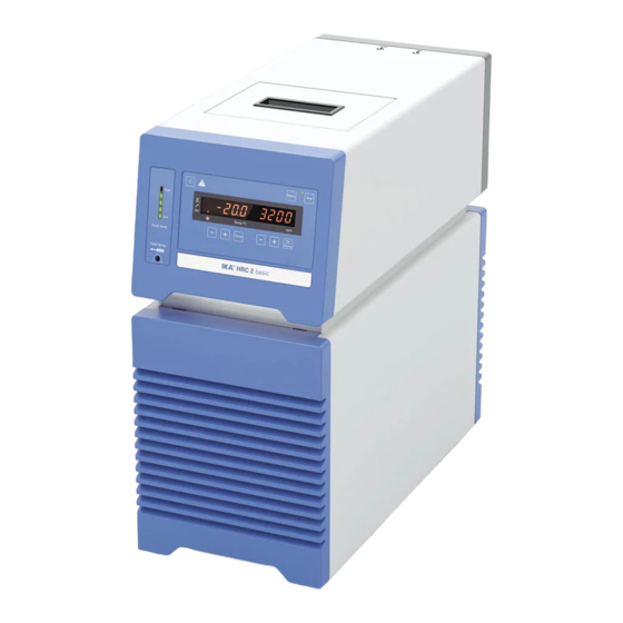
Device setup Fig. 1 Item Designation Operator panel and display Handle Venting grid Filling opening lid RS 232 port USB port Overflow Backflow Power socket Power switch Pump connector OUT Pump connector IN... -
Page 3: Table Of Contents
Delivery scope �������������������������������������������������������������������������������������������������������������������������������������������������������7 Preparations ..............................7 Setting up �������������������������������������������������������������������������������������������������������������������������������������������������������������7 Connecting the tubings �����������������������������������������������������������������������������������������������������������������������������������������7 Filling and draining ������������������������������������������������������������������������������������������������������������������������������������������������8 Fluid (Standard information for IKA fluid) ������������������������������������������������������������������������������������������������������������9 ® Moving the device ����������������������������������������������������������������������������������������������������������������������������������������������10 Operator panel and display ........................10 Setting the safety temperature ........................11 Commissioning ............................ -
Page 4: Declaration Of Conformity
Declaration of Conformity We declare under our sole responsibility that this product corresponds to the regulations 2014/35/EU, 2006/42/EC, 2014/30/EU and 2011/65/EU and conforms with the standards or other normative documents: EN 61010-1, EN 61010-2-010, EN 61326-1, EN 60529 and DIN 12876-1� Explication of warning symbols Indicates an (extremly) hazardous situation, which, if not avoided, will result in death, DANGER... -
Page 5: Safety Instructions
70 ° C� sions or comprehensive monitoring equipment� • Process pathogenic material only in closed vessels under a suitable fume hood� Please contact IKA application sup- • After a power failure during operation, the device may ®... -
Page 6: Disposal Of The Device
The safety of the user cannot be guaranteed: • Range of use (indoor use only): - If the device is operated with accessories that are not sup- - Laboratories - Schools plied or recommended by IKA � ® - Pharmacies - Universities - If the device is operated improperly or in contrary to the specifications�... -
Page 7: Unpacking
“Overflow” connector� • Connecting the tubings: - Connect the “Backflow” connector (8) to IKA calo- ® - Unscrew the union nuts and stoppers using a wrench rimeter with a suitable hose�... -
Page 8: Filling And Draining
Note: Please note the permissible temperature range of hoses� For hot fluids we recommend the IKA LT 5�20 ® hoses� When the external system is not necessary, please seal the pump connector IN and OUT with the existing union Drain port nuts and stoppers�... -
Page 9: Fluid)
• Fluids (Standard information for IKA fluid): ® ® Operating temperature Operating temperature Safety temperature Flash point Designation range for open bath range for closed bath (°C) (°C) application applications (°C) (°C) CF�EG28�N10�80�8 -10 ��� 80 -10 … 80 CF�EG39�N20�80�16 -20 …... -
Page 10: Moving The Device
• Moving the device: Empty all fluid in the bath before moving device from one place to other place� The device can be lifted up and moved by using the top handles or the bottom handles� It can also be moved on flat surface by lifting and pushing the front of the device�... -
Page 11: Setting The Safety Temperature
Setting the safety temperature Setting the safety temperature with screwdriver delivered The safety temperature setting will appear on the display� with the device� Safety temperature Factory setting: approximate max� value Adjustment range: 0 to 110 °C� Warning: The safety temperature must always be set to at least 25 ºC lower than the flash point of the fluid used�... -
Page 12: Menu Settings
IKA fluid)”� ® The maximum adjustable value: 100 °C� This value can be limited additionally by the selected fluid (No�, see “Fluid (Standard information for IKA fluid)”� ® Note: The maximum value is limited by the set safety temperature�... -
Page 13: Temperature Control Type (Auto)
• Temperature control type (AUTO) (heating): Proportional coefficient of PID (Kp 1) The proportional coefficient Kp is the controller ampli- AUTO 1: fication and determines how strongly the control devia- AUTO 1 is the default setting� The default PID settings are tion (the difference between the target temperature and used automatically�... -
Page 14: Interface And Output
RS 232 applies in accor- dance with DIN 66 259 Part 1� USB device driver: - Transmission procedure: asynchronous character transmis- First, download the latest driver for IKA devices with USB ® sion in start-stop mode�... - Page 15 1�1)� The NAMUR commands and the additional specific IKA co mmands serve only as low level commands for communica- ®...
-
Page 16: Maintenance And Cleaning
- machine type before assembly� - manufacturing number, see type plate Note: Don’t touch the condenser surface with hard parts� - item and designation of the spare parts, see www.ika.com - software version� Cleaning: Disconnect main plug prior to Repair:... -
Page 17: Error Codes
Silicone tube (nominal width 12 mm) Labworldsoft ® H.PUR.8 PUR tube (nominal width 8 mm) H.PUR.12 PUR tube (nominal width 12 mm) H.FKM.8 FKM tube (nominal width 8 mm) H.FKM.12 FKM tube (nominal width 12 mm) See more accessories on www.ika.com�... -
Page 18: Technical Data
Technical data Operating voltage 230 ± 10 % / 115 ± 10 % / 100 ± 10 % Frequency 50 / 60 Max� input power 1800 (230 VAC) / 1500 (115 VAC) / 1210 (100 VAC) Working temperature range °C - 20 ���... -
Page 19: Warranty
Warranty In accordance with IKA warranty conditions, the warranty The warranty does not cover worn out parts, nor does it ap- ® period is 24 months� For claims under the warranty please ply to faults resulting from improper use, insufficient care or contact your local dealer�... - Page 20 -Werke GmbH & Co.KG ® Janke & Kunkel-Str� 10 D-79219 Staufen Tel� +49 7633 831-0 Fax +49 7633 831-98 sales@ika�de www.ika.com...
Need help?
Do you have a question about the HRC 2 basic and is the answer not in the manual?
Questions and answers