IKA ICC basic Manual
Hide thumbs
Also See for ICC basic:
- Manual (22 pages) ,
- Operating instructions manual (20 pages) ,
- Operating instructions manual (23 pages)

Subscribe to Our Youtube Channel
Related Manuals for IKA ICC basic


Summary of Contents for IKA ICC basic
- Page 1 20000004066b ICC basic_062017 ® ICC basic...
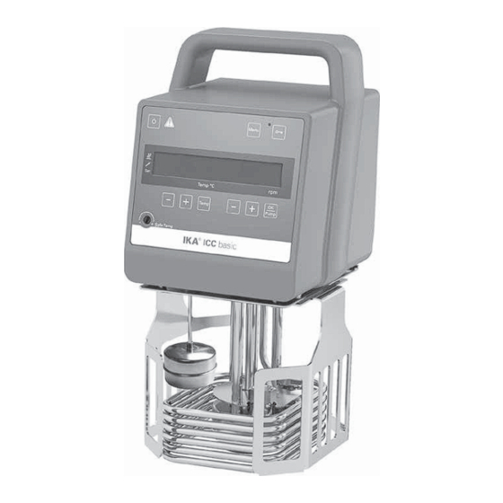
- Page 2 Fig. 1 Fig. 2 Item Designation Operator panel and display Mains switch Power socket Buoyage Heater Stand Pt 100 + Pt 1000 temperature sensor Handle RS 232 port USB port Clamp Cable clip...
-
Page 3: Table Of Contents
Source language: German Contents Page Declaration of Conformity ..........................4 Explication of warning symbols ........................4 Safety instructions ............................5 General information ............................. 5 Fluids ................................... 6 Correct use ..............................7 Use ..................................7 Range of use (indoor use only) ..........................7 Unpacking .............................. -
Page 4: Declaration Of Conformity
Declaration of Conformity We declare under our sole responsibility that this product corresponds to the regulations 2014/35/EU, 2006/42/EC, 2014/30/EU and 2011/65/EU and conforms with the standards or standardized documents: EN 61010-1, EN 61010-2-010, EN 61010-2-051, EN 61326-1, EN 60529, DIN 12876-1 und EN ISO 12100. Explication of warning symbols Indicates an (extremly) hazardous situation, which, if not avoided, will result in death, DANGER... -
Page 5: Safety Instructions
fire or explosions or comprehensive monitoring equipment. • Be careful when filling a hot bath. • Process pathogenic material only in closed vessels under a suitable fume hood. Please contact IKA ® application At high operating tempera- support if you have any question. -
Page 6: Fluids
It is dangerous to touch the • Continuous monitoring of the bath and the filling level of WARNING heater. The temperature of the the bath fluid is required, especially at high temperatures. heater can be very high. • For optimum temperature stability, the fluids viscosity should be 50 mm /s or less at its lowest operating tem- •... -
Page 7: Correct Use
- If the device is operated with accessories that are not sup- - Laboratories - Schools ® plied or recommended by the IKA - Pharmacies - Universities - If the device is operated improperly or in contrary to the ®... -
Page 8: Fluids
Fluids (Standard information for IKA fluid): ® Operating temperature Operating temperature Safety temperature Flash point Designation range for open bath range for closed bath (°C) (°C) application applications (°C) (°C) CF.EG28.N10.80.8 -10 ... 80 -10 … 80 CF.EG39.N20.80.16 -20 … 80 -20 …... -
Page 9: Operator Panel And Display
Operator panel and display Fig. 3 Item Designation Function Switch on/off the circulator. On/Off button: Adjust the safety temperature limit with delivered screwdriver. Adjustable safety circuit: LED display: Display the settings and actual values. “Temp” button: Start/stop the heating function. “Temp (+)”... -
Page 10: Commissioning
Commissioning Check whether the voltage specified on the type plate After that, following two screens appear alternatively. matches the mains voltage available. The power socket used must be earthed (protective earthing). If above conditions are met, the device is ready for opera- tion after plugging in the mains plug. -
Page 11: Menu Settings
Menu settings • Menu structure: Default settings activated MODE 150 °C Maximum temperature (HI T) -20 °C Minimum temperature (LO T) 3200 rpm Maximum speed (HI R) 1000 rpm Minimum speed (LO R) Fluid type (FLUI) Menu activated The type of temperature PID control arithmetic (AUTO) AUTO 1 15.0 Proportional coefficient of PID (Kp 1) -
Page 12: Alarm And Key Tone (Beep)
Proportional coefficient of PID (Kp 1): AUTO 1: AUTO 1 is the default setting. The optimum settings are determined automatically. Heat-up curve in auto-tuning control (AUTO 1): The proportional coefficient Kp is the controller ampli- fication and determines how strongly the control devia- °C tion (the difference between the target temperature and actual temperature) directly affects the control variable... -
Page 13: Interface And Output
(Slave). USB device drivers: - The device sends only at the computer’s request. Even ® First, download the latest driver for IKA devices with USB fault indications cannot be sent spontaneously from the interface from: device to the computer (automation system). - Page 14 The NAMUR commands and the additional specific IKA ® co mmands serve only as low level commands for communication between the device and the PC. With a suitable terminal or communications programme these commands can be transmit- ® ® ted directly to the circulator equipment. The IKA...
-
Page 15: Maintenance And Cleaning
- machine type - manufacturing number, see type plate Cleaning: - item and designation of the spare part, see www.ika.com, spare parts diagram and list For cleaning disconnect the mains - Software version. plug! Use only cleaning agents which have been approved by Repair: ®... -
Page 16: Accessories
Medium cover (for IB pro 12) CM.ICC Large cover (for IB eco 18, IB pro 20) CL.ICC • Additional accessories: Pump set PCS.ICC PC 1.1 Cable (RS 232) USB 2.0 cabel A - Micro B ® Labworldsoft See more accessories on www.ika.com. -
Page 17: Technical Data
Technical data Operating voltage 230 ± 10 % 115 ±10 % 100 ± 10 % Frequency 50/60 Max. input power 2100 (230 VAC) 1100 (115 VAC) 860 (100 VAC) Working temperature range (RT+10 °C at 1000 rpm) RT + 10 ... 150 °C Operating temperature range (with forced cooling) °C... -
Page 18: Warranty
Warranty In accordance with IKA ® warranty conditions, the warranty The warranty does not cover worn out parts, nor does period is 24 months. For claims under the warranty please it apply to faults resulting from improper use, insufficient contact your local dealer. You may also send the machine...
Need help?
Do you have a question about the ICC basic and is the answer not in the manual?
Questions and answers