Advertisement
Quick Links
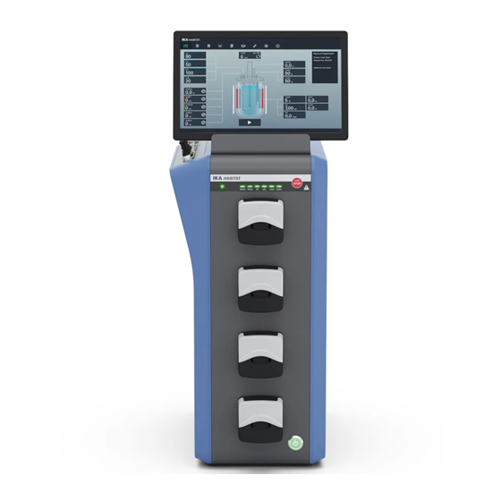
HABITAT cell
HABITAT photo cell
HABITAT cell cct
HABITAT photo cell cct
HABITAT ferment
HABITAT photo ferment
HABITAT ferment cct
HABITAT photo ferment cct
HABITAT cell vessel
0.5 L sw
0.5 L dw
1 L sw
1 L dw
2 L sw
2 L dw
5 L sw
5 L dw
10 L dw
HABITAT ferment vessel
0.5 L dw
1 L dw
2 L sw
2 L dw
5 L sw
5 L dw
10 L dw
Advertisement


Need help?
Do you have a question about the HABITAT cell and is the answer not in the manual?
Questions and answers