Table of Contents
Advertisement
Quick Links
Advertisement
Table of Contents

Subscribe to Our Youtube Channel
Related Manuals for Leuze electronic BCL558i


Summary of Contents for Leuze electronic BCL558i
- Page 1 Bar code reader TECHNICAL DESCRIPTION...
- Page 2 © 2013 Leuze electronic GmbH + Co. KG In der Braike 1 D-73277 Owen - Teck / Germany Phone: +49 7021 573-0 Fax: +49 7021 573-199 http://www.leuze.com info@leuze.de Leuze electronic 558i...
- Page 3 558i Device information - main menu The main menus BCL558i SF 102 Information about Leuze electronic • Device type GmbH & Co. KG • Software version SW: V 1.4 HW:1 SN: 0704-081894 001 • Hardware version • Serial number Network settings - main menu...
-
Page 4: Table Of Contents
General specifications of the bar code readers ....... 33 Leuze electronic... - Page 5 BT 59 mounting device ........... 69 548i Leuze electronic...
- Page 6 Installing the USB driver ..........105 Leuze electronic...
- Page 7 General 'online' commands ..........156 548i Leuze electronic...
- Page 8 Module 0.5 ............188 Leuze electronic...
- Page 9 "Medium Density" reading field curve for oscillating-mirror scanners with heating ....59 Figure 5.25: Lateral "Medium Density" reading field curve for oscillating-mirror scanners with heating..59 Figure 5.26: "Low Density" reading field curve for line scanner with heating (without deflection mirror) ... 60 558i Leuze electronic...
- Page 10 Data exchange sequence diagram - example 1 ..............139 Figure 10.9: Configuration of example 2 - module definition with generic module........140 Figure 10.10: Configuration of example 2 - module definition with the EDS file ......... 140 Leuze electronic 558i...
- Page 11 Cable structure of Industrial Ethernet connection cable ............179 Table 13.9: Bus connection cables for the BCL 558i................180 Figure 15.1: Bar code sample labels (module 0.3) .................. 187 Figure 15.2: Bar code sample labels (module 0.5) .................. 188 558i Leuze electronic...
-
Page 12: General Information
You can find the Declaration of Conformity of the devices in the appendix of the manual on page 182. The manufacturer of the product, Leuze electronic GmbH & Co. KG in D-73277 Owen, possesses a certified quality assurance system in accordance with ISO 9001. -
Page 13: Safety Notices
The bar code readers of the BCL 500i series are especially designed for the following areas of application: • Storage and conveying technologies, in particular for object identification on fast- moving conveyor belts • Pallet transportation applications • Automobile sector • Omnidirectional reading 558i Leuze electronic... -
Page 14: Working Safely
If, however, a stationary beam is emitted, the failing bar code reader should be disconnected from its power source immediately. CAUTION: Use of controls or adjustments or performance of procedures other than specified herein may result in hazardous light exposure. Leuze electronic 558i... -
Page 15: Figure 2.1: Attachment Of The Stick-On Labels With Warning Notices At The Bcl 558I
BCL 558i, attach them instead in the immediate vicinity of the BCL 558i in such a way that it is not necessary to look into the laser beam when reading the notices. 558i Leuze electronic... -
Page 16: Fast Commissioning / Operating Principle
• The reading distance lies in the middle area of the reading field. • The bar code labels are of good print quality and have good contrast ratios. • You do not use high-gloss labels. • There is no direct sunlight. Leuze electronic 558i... -
Page 17: Electrical Connection Bcl 558
DHCP server. Please make certain that each participant in the Ethernet has its own unique IP address. This can be set by a DHCP server in the primary system or through manual address assignment. 558i Leuze electronic... -
Page 18: Starting The Device
In this case, the respective configuration must be entered and adapted manually for each device. The parameter download from the control to the BCL 558i is performed during every establishment of connection. Since the parameters are stored centrally in the control, this helps during device exchange. Leuze electronic 558i... -
Page 19: Figure 3.2: Manually Setting The Ip Address
• Set these values on the BCL 558i. Via webConfig: Configuration -> Communication -> Ethernet interface. Notice! If the IP address is set via the webConfig tool, then it becomes active after transfer to the device. A restart is not required. 558i Leuze electronic... -
Page 20: Figure 3.3: Generic Ethernet Module
122; min 1 byte - up to max. 263 bytes for the default output assembly) • The address and length of the configuration assembly (instance 190; 3 bytes) For the exact description of the assemblies for input/output and configuration, please refer to chapter 10. Leuze electronic 558i... -
Page 21: Further Settings
• Control of the switching outputs Configure the connected switching outputs according to your requirements. To do this, first set the I/O mode to Output and then configure the switching behavior: • Via webConfig: Configuration -> Device -> Switching inputs/outputs 558i Leuze electronic... -
Page 22: Bar Code Reading
Alternatively, you can connect a photoelectric sensor or a 24 V DC switching signal to the SW IN/OUT socket for read activation. To do this, however, you must appropriately configure the switching input (see chapter 7.2.3 "SW IN/OUT – Switching input/switching output"). Leuze electronic 558i... -
Page 23: Device Description
The interfaces (RS 232, RS 485 and RS 422) integrated in the various device models and the fieldbus systems (PROFIBUS DP, PROFINET-IO, Ethernet TCP/IP / UDP and EtherNet/IP) of the BCL 500i series bar code readers offer optimum connection to the supe- rior host system. 558i Leuze electronic... -
Page 24: Characteristics Of The Bar Code Readers Of The Bcl 500 Series
Play concept enables easy networking and very simple commissioning: Directly connect the respective fieldbus and all configuration is performed with no additional software. For decoding bar codes, the bar code readers of the BCL 500i series make available the proven CRT decoder with code fragment technology: Leuze electronic 558i... -
Page 25: Figure 4.2: Possible Bar Code Orientation
The four freely configurable switching inputs/outputs "SWIO 1 … SWIO 4" can be assigned various functions and control e.g. activation of the BCL 558i or external devices, such as a PLC. System, warning and error messages provide assistance in setup/troubleshooting during commissioning and read operation. 558i Leuze electronic... -
Page 26: Device Construction
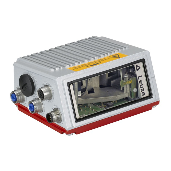
Device construction Reading window USB interface M12 connection technology Dovetail mounting and 4 mounting threads Display, LEDs and buttons Dovetail mounting and 2 mounting threads Figure 4.3: Device construction Leuze electronic 558i... -
Page 27: Reading Techniques
• with bar codes having very short bar lengths. • when the ladder code is turned out of the vertical position (tilt angle). • when the scanning distance is large. Figure 4.4: Deflection principle for the line scanner 558i Leuze electronic... -
Page 28: Line Scanner With Oscillating Mirror
• when the bar code is turned out of the horizontal position. • when the scanning distance is large. • when a large reading field (reading window) has to be covered. Figure 4.5: Deflection principle for the line scanner with oscillating mirror add-on Leuze electronic 558i... -
Page 29: Omnidirectional Reading
In order to read arbitrarily oriented bar codes on an object, at least 2 bar code readers are necessary. If the bar code is not printed over-square, i.e. bar length > code length, bar code readers with integrated code fragment technology are necessary. Figure 4.6: Principle arrangement for omnidirectional reading 558i Leuze electronic... -
Page 30: Fieldbus Systems
• BootP Notice! The BCL 558i communicates via the Common Industrial Protocol (CIP). CIP Safety, CIP Sync and CIP Motion are not supported by the BCL 558i. Further information on commissioning can be found in chapter 10. Leuze electronic 558i... -
Page 31: Ethernet - Star Topology
DHCP server. PC / PLC host interface 558i 192.168.60.xxx Other network participants 558i 192.168.60.yyy Figure 4.7: Ethernet with star topology Notice! The BCL 558i does not support the DLR (Device Level Ring) ring structure determined by the ODVA. 558i Leuze electronic... -
Page 32: Ethernet - Linear Topology
BootP or webConfig tool. The maximum length of a segment (connection from the hub to the last participant) is limited to 100m. Notice! The BCL 558i does not support the DLR (Device Level Ring) ring structure determined by the ODVA. Leuze electronic 558i... -
Page 33: Heater
USB connection on the BCL 558i. Then, take the connector hood of the USB memory stick and screw this over the plugged-in USB memory stick to the service interface to close the system and ensure protection class IP 65. 558i Leuze electronic... -
Page 34: Autoreflact
You will find a matching reflector in Accessories, and more are available on request. Figure 4.10: Reflector arrangement for autoReflAct The autoReflAct function uses the scanning beam to simulate a photoelectric sensor and thus permits an activation without additional sensory mechanism. Leuze electronic 558i... -
Page 35: Reference Codes
BCL 558i. Afterward, bar codes with the same code type and number of digits are recognized and decoded. 558i Leuze electronic... -
Page 36: Specifications
Codabar, Code 93, GS 1 Databar Bar code contrast (PCS) >= 60% External light tolerance 2000 lx (on the bar code) Number of bar codes per scan 6 Table 5.1: Specifications of the BCL 558i line scanners without heating Leuze electronic 558i... - Page 37 Specifications of the BCL 558i line scanners without heating This is a Class A product. In a domestic environment this product may cause radio interference, in which case the operator may be required to take adequate measures. 558i Leuze electronic...
-
Page 38: Oscillating-Mirror Scanner
Line scanner with deflection mirror Notice! Please note: the BCL 558i line scanner with deflection mirror (perpendicular beam exit) is currently not available. Specifications are the same as for line scanner without heating with the following differ- ences: Leuze electronic 558i... -
Page 39: Heating Models Of The Bar Code Readers
(around 30min), when the inside temperature rises above 15°C, the temperature switch connects the BCL 558i to the supply voltage. This is followed by the self test and the changeover to read operation. The "PWR" LED lights up showing overall readiness for operation. 558i Leuze electronic... -
Page 40: Line Scanner With Heating
Wiring through of the voltage supply to multiple heating devices is not permissible. Standard, M12 ready-made cable not usable (insufficient cable cross-section) Environmental data Operating temperature range -35°C … +40°C Storage temperature range -20°C … +70°C Table 5.4: Specifications of the BCL 558i line scanners with heating Leuze electronic 558i... -
Page 41: Oscillating-Mirror Scanner With Heating
Wiring through of the voltage supply to multiple heating devices is not permissible. Standard, M12 ready-made cable not usable (insufficient cable cross-section) Environmental data Operating temperature range -35°C … +40°C Storage temperature range -20°C … +70°C Table 5.5: Specifications of the BCL 558i oscillating-mirror scanners with heating 558i Leuze electronic... -
Page 42: Line Scanner With Deflection Mirror And Heating
Wiring through of the voltage supply to multiple heating devices is not permissible. Standard, M12 ready-made cable not usable (insufficient cable cross-section) Environmental data Operating temperature range -35°C … +40°C Storage temperature range -20°C … +70°C Table 5.6: Specifications of the BCL 558i deflection mirror scanners with heating Leuze electronic 558i... -
Page 43: Dimensioned Drawings
Dimensioned drawings 5.3.1 Line scanner with / without heating deep deep deep A – Optical axis Figure 5.1: Dimensioned drawing BCL 558i line scanner S…102 558i Leuze electronic... -
Page 44: Deflection Mirror Scanner With / Without Heating
B – Optical adjustment range C – Opening angle The opening angle is reduced on devices with heating, see "Reading field curves for heating devices" on page 54. Figure 5.2: Dimensioned drawing BCL 558i deflection-mirror scanner S…100 Leuze electronic 558i... -
Page 45: Oscillating-Mirror Scanner With / Without Heating
C – Opening angle The optical swivel range and the opening angle are reduced on devices with heating, see "Reading field curves for heating devices" on page 54. Figure 5.3: Dimensioned drawing BCL 558i oscillating-mirror scanner O…100 558i Leuze electronic... -
Page 46: Type Overview Bcl 558
Line scanner, beam exit at the front, with heating 50122784 558i OL 100 H Oscillating-mirror scanner with heating 50122772 Table 5.7: Type overview BCL 558i Notice! Please note: the BCL 558i line scanner with deflection mirror (perpendicular beam exit) is currently not available. Leuze electronic 558i... -
Page 47: Reading Field Curves / Optical Data
Therefore, above all, the module of a bar code is decisive for the size of the reading field. Notice! A rule of thumb: The smaller the module of the bar code is, the smaller the maximum reading distance and reading field width will be. 558i Leuze electronic... -
Page 48: Reading Field Curves
Distance acc. to reading field curves Figure 5.5: Zero position of the reading distance Reading conditions for the reading field curves Bar code type 2/5 Interleaved Ratio 1:2,5 ANSI specification class A Reading rate > 75% Table 5.8: Reading conditions Leuze electronic 558i... -
Page 49: High Density (N) Optics: Bcl 558I Sn 100/102
"High Density" reading field curve for line scanner (with/without deflection mirror) The reading field curve applies for the reading conditions stated in table 5.8. Notice! Please note: the BCL 558i line scanner with deflection mirror (perpendicular beam exit) is currently not available. 558i Leuze electronic... -
Page 50: High Density (N) Optics: Bcl 558I On 100
= 0,35 m = 0,5 -100 -200 -300 -400 -100 1000 Read distance [mm] Figure 5.8: Lateral "High Density" reading field curve for oscillating-mirror scanners The reading field curves apply for the reading conditions stated in table 5.8. Leuze electronic 558i... -
Page 51: Medium Density (M) Optics: Bcl 558I Sm 100/102
"Medium Density" reading field curve for line scanner (with/without deflection mirror) The reading field curves apply for the reading conditions stated in table 5.8. Notice! Please note: the BCL 558i line scanner with deflection mirror (perpendicular beam exit) is currently not available. 558i Leuze electronic... -
Page 52: Medium Density (M) Optics: Bcl 558I Om 100
= 1,0 -100 -200 -300 -400 -100 1000 1100 Read distance [mm] Figure 5.11: Lateral "Medium Density" reading field curve for oscillating-mirror scanners The reading field curves apply for the reading conditions stated in table 5.8. Leuze electronic 558i... -
Page 53: Low Density (F) Optics: Bcl 558I Sf 100/102
Figure 5.12: "Low Density" reading field curve for line scanner (with/without deflection mirror) The reading field curves apply for the reading conditions stated in table 5.8. Notice! Please note: the BCL 558i line scanner with deflection mirror (perpendicular beam exit) is currently not available. 558i Leuze electronic... -
Page 54: Low Density (F) Optics: Bcl 558I Of 100
900 1000 1100 1200 1300 1400 1500 1600 1700 -100 Read distance [mm] Figure 5.14: Lateral "Low Density" reading field curve for oscillating-mirror scanners The reading field curves apply for the reading conditions stated in table 5.8. Leuze electronic 558i... -
Page 55: Ultra Low Density (L) Optics: Bcl 558I Sl 102
Figure 5.15: "Ultra Low Density" reading field curve for line scanner without deflection mirror The reading field curves apply for the reading conditions stated in table 5.8. Notice! Please note: the BCL 558i line scanner with deflection mirror (perpendicular beam exit) is currently not available. 558i Leuze electronic... -
Page 56: Ultra Low Density (L) Optics: Bcl 558I Ol 100
1000 1200 1400 1600 1800 2000 2200 2400 2600 Read distance [mm] Figure 5.17: Lateral "Ultra Low Density" reading field curve for oscillating-mirror scanners The reading field curves apply for the reading conditions stated in table 5.8. Leuze electronic 558i... -
Page 57: Reading Field Curves For Heating Devices
-100 -200 -300 -400 -100 1000 Read distance [mm] Figure 5.18: "High Density" reading field curve for line scanner with heating (without deflection mirror) The reading field curve applies for the reading conditions stated in table 5.8. 558i Leuze electronic... -
Page 58: High Density (N) Optics: Bcl 558I Sn 100 H
Figure 5.19: "High Density" reading field curve for line scanner with heating (with deflection mirror) The reading field curve applies for the reading conditions stated in table 5.8. Notice! Please note: the BCL 558i line scanner with deflection mirror (perpendicular beam exit) is currently not available. Leuze electronic 558i... -
Page 59: High Density (N) Optics: Bcl 558I On 100 H
= ±12˚ -100 -200 -300 -400 -100 1000 Read distance [mm] Figure 5.21: Lateral "High Density" reading field curve for oscillating-mirror scanners with heating The reading field curves apply for the reading conditions stated in table 5.8. 558i Leuze electronic... -
Page 60: Medium Density (M) Optics: Bcl 558I Sm 102 H
-200 -300 -400 -100 1000 1100 Read distance [mm] Figure 5.22: "Medium Density" reading field curve for line scanner with heating (without deflection mirror) The reading field curves apply for the reading conditions stated in table 5.8. Leuze electronic 558i... -
Page 61: Medium Density (M) Optics: Bcl 558I Sm 100 H
Figure 5.23: "Medium Density" reading field curve for line scanner with heating (with deflection mirror) The reading field curves apply for the reading conditions stated in table 5.8. Notice! Please note: the BCL 558i line scanner with deflection mirror (perpendicular beam exit) is currently not available. 558i Leuze electronic... -
Page 62: Medium Density (M) Optics: Bcl 558I Om 100 H
= ±12˚ -100 -200 -300 -400 -100 1000 1100 Read distance [mm] Figure 5.25: Lateral "Medium Density" reading field curve for oscillating-mirror scanners with heating The reading field curves apply for the reading conditions stated in table 5.8. Leuze electronic 558i... -
Page 63: Low Density (F) Optics: Bcl 558I Sf 102 H
900 1000 1100 1200 1300 1400 1500 1600 1700 Read distance [mm] Figure 5.26: "Low Density" reading field curve for line scanner with heating (without deflection mirror) The reading field curves apply for the reading conditions stated in table 5.8. 558i Leuze electronic... -
Page 64: Low Density (F) Optics: Bcl 558I Sf 100 H
Figure 5.27: "Low Density" reading field curve for line scanner with heating (with deflection mirror) The reading field curves apply for the reading conditions stated in table 5.8. Notice! Please note: the BCL 558i line scanner with deflection mirror (perpendicular beam exit) is currently not available. Leuze electronic 558i... -
Page 65: Low Density (F) Optics: Bcl 558I Of 100 H
900 1000 1100 1200 1300 1400 1500 1600 1700 -100 Read distance [mm] Figure 5.29: Lateral "Low Density" reading field curve for oscillating-mirror scanners with heating The reading field curves apply for the reading conditions stated in table 5.8. 558i Leuze electronic... -
Page 66: Ultra Low Density (L) Optics: Bcl 558I Sl 102 H
1800 2000 2200 2400 2600 Read distance [mm] Figure 5.30: "Ultra Low Density" reading field curve for line scanner with heating (without deflection mirror) The reading field curves apply for the reading conditions stated in table 5.8. Leuze electronic 558i... -
Page 67: Ultra Low Density (L) Optics: Bcl 558I Ol 100 H
1400 1600 1800 2000 2200 2400 2600 Read distance [mm] Figure 5.32: Lateral "Ultra Low Density" reading field curve for oscillating-mirror scanners with heating The reading field curves apply for the reading conditions stated in table 5.8. 558i Leuze electronic... -
Page 68: Installation And Mounting
Save the original packaging for later storage or shipping. If you have any questions concerning your shipment, please contact your supplier or your local Leuze electronic sales office. Observe the applicable local regulations when disposing of the packaging materials. -
Page 69: Mounting The Bcl 558
• Using two M4x6 screws on the rear of the device or using four M4x6 screws on the bottom of the device. • Using a BT 56 mounting device on the two fastening grooves. 6.2.1 Fastening with M4 x 6 screws Figure 6.2: Fastening options using M4x6 threaded holes 558i Leuze electronic... -
Page 70: Bt 56 Mounting Device
558i Clamp profile for mounting to round or oval pipes Ø 16 … 20mm All dimensions in mm A Rod holder, turnable 360° B Rods Ø 16 … 20mm Figure 6.3: BT 56 mounting device Leuze electronic 558i... -
Page 71: Figure 6.4: Mounting Example Of Bcl 558I With Bt 56
Figure 6.4: Mounting example of BCL 558i with BT 56 558i Leuze electronic... -
Page 72: Bt 59 Mounting Device
For further information, see the notices in chapter 6.3! Please refer to chapter 5.6 for the permissible minimum and maximum distances between the BCL 558i and the labels to be read. Leuze electronic 558i... -
Page 73: Device Arrangement
• The reading distance lies in the middle area of the reading field. • The bar code labels are of good print quality and have good contrast ratios. • You do not use high-gloss labels. • There is no direct sunlight. 558i Leuze electronic... -
Page 74: Avoiding Total Reflection - Line Scanner
This will result in an angle of inclination of approx. 25°. Notice! Please note: the BCL 558i line scanner with deflection mirror (perpendicular beam exit) is currently not available. Leuze electronic 558i... -
Page 75: Mounting Location
• Mount in such a way that the device is protected from draft and wind; mount additional shields if necessary. Notice! When installing the BCL 558i in a protective housing, it must be ensured that the scanning beam can exit the protective housing without obstruction. 558i Leuze electronic... -
Page 76: Possible Read Angles Between Bcl 558I And Bar Code
Styrofoam balls. In doing so, avoid leaving fingerprints on the front cover of the BCL 558i. Attention! Do not use aggressive cleaning agents such as thinner or acetone for cleaning the device. Leuze electronic 558i... -
Page 77: Electrical Connection
For the locations of the individual device connections, please refer to the device detail shown below. Notice! The corresponding mating connectors and ready-made cables are available as accessories for all connections. For additional information, refer to chapter chapter 13. Figure 7.1: Location of the electrical connections 558i Leuze electronic... -
Page 78: Safety Notices For The Electrical Connection
500i series are designed in accordance with safety class III for supply by PELV (protective extra-low voltage with reliable disconnection). Notice! Protection class IP 65 is achieved only if the connectors and caps are screwed into place! Leuze electronic 558i... -
Page 79: Electrical Connection Of The Bcl 558
BUS OUT SWIO_3 TD+ 1 TD+ 1 SWIO_4 M12 socket M12 socket M12 plug (D-coded) (D-coded) (A-coded) Figure 7.2: Connections of the BCL 558i Described in detail in the following are the individual connections and pin assignments. 558i Leuze electronic... -
Page 80: Pwr - Voltage Supply And Switching Input/Outputs 3 And 4
The two switching inputs/outputs SWIO_1 and SWIO_2 are located on the SW IN/OUT M12 socket and are described in chapter 7.2.3. The other two (SWIO_3 and SWIO_4) of the four freely configurable switching inputs/outputs are located on the PWR M12 connector. Leuze electronic 558i... -
Page 81: Figure 7.3: Switching Input Connection Diagram Swio_3 And Swio_4
Switching output connection diagram SWIO_3 / SWIO_4 Attention! Each configured switching output is short-circuit proof! Do not load the respective switching output of the BCL 558i with more than 60mA at +10 … +30VDC in normal operation! 558i Leuze electronic... -
Page 82: Service - Usb Interface (Type A)
Leuze electronic GmbH + Co. can be connected to the provided USB service interface. With this Leuze memory stick, protection class IP 65 is also ensured. For further information, please refer to chapter 4.7 and chapter 10.10.2 of this documentation! -
Page 83: Sw In/Out - Switching Input/Switching Output
If, for example, the inverted sensor output is connected to pin 2, and pin 2 of the bar code reader is, at the same time, configured as an output (and not as an input), the switching output malfunctions. 558i Leuze electronic... -
Page 84: Figure 7.6: Switching Output Connection Diagram Swio_1 / Swio_2
The functions of the individual switching inputs/outputs are programmed via the display or via configuration in the webConfig tool under the Switching input or Switching output heading. For further information, see also "Commissioning and configuration" on page 110. Leuze electronic 558i... -
Page 85: Host / Bus In For Bcl 558I
HOST / BUS IN cable assignments on RJ-45 Notice for connecting the Ethernet interface! Ensure adequate shielding. The entire connection cable must be shielded and earthed. The RD+/RD- and TD+/TD- wires must be stranded in pairs. Use CAT 5 cable for the connection. 558i Leuze electronic... -
Page 86: Bus Out For The Bcl 558I
Use CAT 5 cable for the connection. Notice! For the BCL 558i as standalone device or as the last participant in a linear topology, termination on the BUS OUT socket is not mandatory! Leuze electronic 558i... -
Page 87: Ethernet Topologies
This address must be specified by the network administrator. Alternatively, the BCL 558i can also be configured as a DHCP client and then automatically receive its address from a DHCP server. Information on the necessary configuration steps can be found in chapter 10. 558i Leuze electronic... -
Page 88: Ethernet Wiring
Ethernet twisted pairs (min. Cat. 3) and last BCL shielded 100Base-TX twisted pair (min. Cat. 5) BCL – power not necessary supply unit not necessary Switching input not necessary Switching output Table 7.6: Cable lengths and shielding Leuze electronic 558i... -
Page 89: Display And Control Panel
Internal device error (Error) -> The device must be sent in for inspection Bar graph The read quality is described on a scale of 0 - 100%. The quality is evaluated based on the "Equal Scans" of the read result configured in the bar code reader. 558i Leuze electronic... -
Page 90: Led Status Indicators
- configuration via the display - no data on the host interface flashes red Device ok, warning set - bar code reading possible - temporary operating fault red continuous light Device error / parameter enable - no bar code reading possible Leuze electronic 558i... -
Page 91: Control Buttons
The menus within a level are selected with the up/down buttons The selected menu item is activated with the enter button Press the ESC button to move up one menu level. When one of the buttons is actuated, the display illumination is activated for 10min. 558i Leuze electronic... - Page 92 Selecting options If options can be selected, the display looks like this: o OFF Standard ----- Unit Select the desired option with the buttons. Activate the option by pressing Leuze electronic 558i...
-
Page 93: Menu Description
The display then shows the bar code reading window with all status information. 8.3.1 The main menus Device information - main menu BCL558i SF 102 This menu item contains detailed information on Leuze electronic • Device type GmbH & Co. KG •... - Page 94 8.3. Only the webConfig tool provides complete configuration options and is largely self-explan- atory. The use of the webConfig tool is described inchapter 9. Notes on commissioning via the webConfig tool can be found in chapter 10. Leuze electronic 558i...
-
Page 95: Parameter Menu
By pressing the enter button after selecting default Parameters to default , all parameters are reset to their standard settings without any further security prompts. In this case, English is selected as the display language. Table 8.1: Parameter handling submenu 558i Leuze electronic... - Page 96 Fourth decodable number of characters. Digits 5 0 to 64 characters Fifth decodable number of characters. Reading reliability Value from 2 to 100 Number or scans required to reliably detect a label. Table 8.2: Decoder table submenu Leuze electronic 558i...
- Page 97 Digits 4 0 to 64 characters Digits 5 0 to 64 characters Reading reliability Value from 2 to 100 Check digit method as decoder 1 Standard Check digit transm. as decoder 1 Standard Table 8.2: Decoder table submenu 558i Leuze electronic...
- Page 98 Digits 4 0 to 64 characters Digits 5 0 to 64 characters Reading reliability Value from 2 to 100 Check digit method as decoder 1 Standard Check digit transm. as decoder 1 Standard Table 8.2: Decoder table submenu Leuze electronic 558i...
- Page 99 No BCL500i function Reading gate Reading gate start/stop start/stop Rd. gate stop Rd. gate start Teach reference code Autoconfig start/stop The function set here is carried out after the switching input is activated. Table 8.3: Digital SWIO submenu 558i Leuze electronic...
- Page 100 The function set here specifies which event activates the switching output. Deactivation function 1 See Activation function 1 for selection No function options The function set here specifies the event that deactivates the switching output. Table 8.3: Digital SWIO submenu Leuze electronic 558i...
- Page 101 Value from 0 to 65535 Pulse duration Value from 0 to 65535 Activation function 4 see switching input/output 1 Invalid read result Deactivation function 4 see switching input/output 1 Reading gate start Table 8.3: Digital SWIO submenu 558i Leuze electronic...
-
Page 102: Table 8.4: Ethernet/Ip Submenu
IP address, gateway and net mask from a BootP server. The manual settings made above have no effect, but are retained and are again active if BootP is deactivated. Table 8.4: EtherNet/IP submenu Leuze electronic 558i... -
Page 103: Language Selection Menu
The setting in the display affects the webConfig tool and vice versa. 8.3.4 Service menu Diagnostics This menu item is used exclusively for service purposes by Leuze electronic. Status messages This menu item is used exclusively for service purposes by Leuze electronic. 558i... -
Page 104: Actions Menu
Contents of the decoded bar code. zzzzzz: Once the bar code has been detected, the laser beam starts to flash. The flash frequency provides visual information on the read quality. The faster the laser beam flashes, the higher the read quality. Leuze electronic 558i... - Page 105 Actions o Stop teach-in RC13xxzzzzzz The following information is displayed: RC13 means that reference code number 1 is stored in RAM. This is always output. defined code type (see auto-setup) defined code information (1 … 63 characters) 558i Leuze electronic...
-
Page 106: Operation
The PWR LED lights up red. You can now set individual parameters via O ON the display. Standard -------- Unit Press the ESC button twice to return to the main menu. Network configuration Information on network configuration can be found in chapter "Commissioning and config- uration" on page 110. Leuze electronic 558i... -
Page 107: Leuze Webconfig Tool
Connecting the SERVICE USB interface The connection to the SERVICE USB interface of the BCL 558i is established via the PC-side USB interface using a special USB cable with 2 type A/A connectors. Figure 9.1: Connecting the SERVICE USB interface 558i Leuze electronic... -
Page 108: Installing The Required Software
Upon successful installation of the USB driver, a BCL 50xi icon automatically appears on the desktop. To check: In the Windows Device Manager, a device called "Leuze electronic, USB Remote NDIS Network Device" appears under the "Network adapter" device class following successful USB registration. -
Page 109: Figure 9.2: Device Manager With Connected Bcl 558I
Figure 9.2: Device Manager with connected BCL 558i Notice! If the installation failed, contact your network administrator: The settings of the firewall used may need to be adjusted. 558i Leuze electronic... -
Page 110: Figure 9.3: The Start Page Of The Webconfig Tool
The individual parameters are – where useful – graphically displayed in order to better illus- trate the meaning of the what are often perceived as abstract parameters. The result is an easy-to-use and practically-oriented user interface! Leuze electronic 558i... -
Page 111: Figure 9.4: Module Overview In The Webconfig Tool
The user interface of the webConfig tool is largely self-explanatory. 9.4.1 Module overview in the Configuration menu The adjustable parameters of the BCL 558i are clustered in modules in the Configuration menu. Figure 9.4: Module overview in the webConfig tool 558i Leuze electronic... - Page 112 • Switching input Activation/deactivation of read processes • Switching output Definition of events which activate/deactivate the switching output • Display Formatting of the data for output on the display • Oscillating mirror (optional) Adjustment of oscillating mirror parameters Leuze electronic 558i...
-
Page 113: Commissioning And Configuration
Notes on the use of the display can be found in chapter 8 "Display and control panel" on page 86. An overview of the menu structure and brief instructions for operating the display can be found in the two fold-out pages at the beginning and end of this technical description. 558i Leuze electronic... -
Page 114: Figure 10.1: Connections Of The Bcl 558I
SW IN/OUT SWIO_1 GND D+ D- U VOUT 1 SWIO_2 HOST / BUS IN BUS OUT SWIO_3 TD+ 1 TD+ 1 SWIO_4 M12 socket M12 socket M12 plug (D-coded) (D-coded) (A-coded) Figure 10.1: Connections of the BCL 558i Leuze electronic 558i... -
Page 115: Starting The Device
The communication parameters are independent of the topology in which the BCL 558i operated (see "Ethernet topologies" on page 84). On delivery, the automatic address assignment via DHCP server is defined as the standard setting of the BCL 558i. 558i Leuze electronic... -
Page 116: Figure 10.2: Manually Setting The Ip Address
• Set these values on the BCL 558i: Via webConfig tool • In the main menu, select Configuration, submenu Communication -> Ethernet interface. • Deactivate the DHCP operation and enter the IP address. Leuze electronic 558i... - Page 117 DHCP activated Exit the Ethernet menu with the ESCAPE button. Notice! If the IP address is set via the webConfig tool, then it becomes active after transfer to the device. A restart is not required. 558i Leuze electronic...
-
Page 118: Figure 10.3: Generic Ethernet Module
• The address and length of the output assembly (instance 120, instance 121 or instance 122; min 1 byte - up to max. 263 bytes for the default output assembly). • The address and length of the configuration assembly (instance 190; 3 bytes). Leuze electronic 558i... -
Page 119: Figure 10.4: New Module
• Open the input dialog for setting the address and additional parameters by double- clicking on the device symbol and make the desired entries here. Under Change, define the combination of input and output assemblies. Figure 10.4: New module • Finally, transmit the values to the control via download. 558i Leuze electronic... -
Page 120: Eds File - General Info
558i is uniquely classified via a class 1 identity object (component of the BCL558i.eds file) for the EtherNet/IP scanner. The identity object contains, among other things, a manufacturer-specific vendor ID, as well as an ID that describes the principle func- tion of the participant. - Page 121 According to ODVA, the BCL 558i is assigned number 43 = 0x2B. Product Code The product code is an ID assigned by Leuze electronic that has no further impact on other objects. Revision Version number of the identity object. Status The device status is displayed in the status byte, the first part of the telegram.
-
Page 122: Class 4 - Assembly
Formula for calculating the assembly length: Length of the assembly = 5 + length of the result/bar code For results/bar codes with length 10, the assembly must be configured with a length of 5 + 10 = 15. Leuze electronic 558i... - Page 123 Formula for calculating the assembly length: Length of the assembly = 9 + length of the result/bar code For results/bar codes with length 10, the assembly must be configured with a length of 9 + 10 = 19. 558i Leuze electronic...
- Page 124 Formula for calculating the assembly length: Length of the assembly = 11 + length of the result/bar code For results/bar codes with length 10, the assembly must be configured with a length of 11 + 10 = 21. Leuze electronic 558i...
-
Page 125: Output Assembly
Formula for calculating the assembly length: Length of the assembly = 8 + length of the entry data For entry data with length 10, the assembly must be configured with a length of 8 + 10 = 18. 558i Leuze electronic... - Page 126 Formula for calculating the assembly length: Length of the assembly = 7 + length of the entry data For entry data with length 10, the assembly must be configured with a length of 7 + 10 = 17. Leuze electronic 558i...
- Page 127 Formula for calculating the assembly length: Length of the assembly = 6 + length of the entry data For entry data with length 10, the assembly must be configured with a length of 6 + 10 = 16. 558i Leuze electronic...
-
Page 128: Configuration Assembly
In the configuration assembly, all parameters have the value 0. Changing the individual default values is possible at any time. The participant is thereby defined in off-line mode; the data must subsequently be transferred to the control. Leuze electronic 558i... -
Page 129: Class 103 - I/O Status And Control
Switching output comparative state SWIO_3 (event counter) Switching output comparative state toggle bit (event counter) Reserved Status (input/output) Output activation Reset Event Counter Switching output comparative state SWIO_4 (event counter) Switching output comparative state toggle bit (event counter) 558i Leuze electronic... - Page 130 If SWOUT switches several times was configured as comparison mode, this bit is toggled each time the event counter is exceeded. The bit is reset to the init. value by resetting the event counter. 0 1 event counter exceeded 1 0 event counter exceeded again Leuze electronic 558i...
-
Page 131: Class 106 - Activation
This control bit signals that the transmitted data have been processed by the master. Only relevant with handshake mode (with ACK), see Mode. 0 1 data has been processed by the master 1 0 data has been processed by the master 558i Leuze electronic... - Page 132 0 1 data reset If the data reset control bit is activated, the following actions are carried out: Deletion of results that may still be stored. Resetting of the attributes of Class 107 - Result data Leuze electronic 558i...
-
Page 133: Class 107 - Result Data
Displays the current activation status. deactivated activated User data or command Distinction between result from the Formatter and answer from the command interpreter. Makes the distinction easy for the user. user data answer from the command interpreter 558i Leuze electronic... - Page 134 Fragment number Current fragment number. Remaining fragments Number of fragments which still have to be read for a complete result. Fragment size Fragment size always corresponds to the configured fragment length, except for the last fragment. Leuze electronic 558i...
-
Page 135: Class 108 - Entry Data
Data rejection (toggle bit) The BCL 558i has rejected the acceptance of the data or the data fragment (also see Data acceptance toggle bit). 0 1 data have been rejected 1 0 data have been rejected 558i Leuze electronic... -
Page 136: Figure 10.5: Connection Between Data Acceptance/Data Rejection/Error Code Attributes
Data rejection (toggle bit) Error code Input-Assembly Figure 10.5: Connection between Data acceptance/Data rejection/Error code attributes New entry (toggle bit) The toggle bit shows whether new entry data are present. 0 1 new result 1 0 new result Leuze electronic 558i... - Page 137 Number of fragments which still have to be transmitted for a complete entry. Fragment size The fragment size should always be identical, except for the last fragment to be transferred. A fragment size of 0 means that the fragmentation is not used. 558i Leuze electronic...
-
Page 138: Class 109 - Device Status And Device Control
This control bit confirms and deletes errors or warnings that may be present in the system. It acts like a toggle bit. 0 1 error acknowledge 1 0 error acknowledge StandBy Activates the standby function. standby off standby on Leuze electronic 558i... -
Page 139: Configuration Example
2 bytes Config: 0 bytes • Example 3 - activation & fragmented result 13 bytes Out: 1 byte Config: 3 bytes • Example 4 - entry data & result 33 bytes Out: 10 bytes Config: 0 bytes 558i Leuze electronic... -
Page 140: Figure 10.6: Configuration Of Example 1 - Module Definition With Generic Module
The following screenshot shows the configuration of the device in the RSLogix 5000 control software. Figure 10.6: Configuration of example 1 - module definition with generic module Figure 10.7: Configuration of example 1 - module definition with the EDS file Leuze electronic 558i... - Page 141 Structure of configuration assembly 190 Since the configuration is not used, the length of the configuration assembly is specified as 0. The device then operates with the default values. In this case, the acknowledge mode is not used. 558i Leuze electronic...
-
Page 142: Figure 10.8: Data Exchange Sequence Diagram - Example 1
User data / command New result (toggle bit) Result data length = 11 Data = "TestLabel01" Result is transmitted to Input-Assembly the PLC Activation signal Deactivation signal via Output-Assembly Figure 10.8: Data exchange sequence diagram - example 1 Leuze electronic 558i... -
Page 143: Figure 10.9: Configuration Of Example 2 - Module Definition With Generic Module
The following screenshot shows the configuration of the device in the RSLogix 5000 control software. Figure 10.9: Configuration of example 2 - module definition with generic module Figure 10.10: Configuration of example 2 - module definition with the EDS file 558i Leuze electronic... - Page 144 Below, examples of what data exchange looks like during two subsequent activations are shown. Switching output 1 reflects the activation signal. Switching output 2 displays whether the result is valid (status input/output I/O 2 = 1] or whether a NoRead has taken place (status input/output I/O 2 = 0). Leuze electronic 558i...
-
Page 145: Figure 10.11: Data Exchange Sequence Diagram - Example 2
Fragment size Number of results Activation status User data / command New result (toggle bit) Result data length Data = "?" Result is transmitted to the PLC Input-Assembly Figure 10.11: Data exchange sequence diagram - example 2 558i Leuze electronic... -
Page 146: Figure 10.12: Configuration Of Example 3 - Module Definition With Generic Module
The following screenshot shows the configuration of the device in the RSLogix 5000 control software. Figure 10.12: Configuration of example 3 - module definition with generic module Figure 10.13: Configuration of example 3 - module definition with the EDS file Leuze electronic 558i... - Page 147 – – – – – – 0x00 108 / 1 / 8 – – – – – – – 0x00 Notice! Bit 0 in the 106 and 107 assemblies must be set for fragmented sending and receiving! 558i Leuze electronic...
-
Page 148: Figure 10.14: Data Exchange Sequence Diagram - Example 3
Number of results Activation status User data / command New result (toggle bit) Waiting for acknowledgement Result data length Result is transmitted to Data = "" the PLC Input-Assembly Figure 10.14: Data exchange sequence diagram - example 3 Leuze electronic 558i... -
Page 149: Figure 10.15: Configuration Of Example 4 - Module Definition With Generic Module
The following screenshot shows the configuration of the device in the RSLogix 5000 control software. Figure 10.15: Configuration of example 4 - module definition with generic module Figure 10.16: Configuration of example 4 - module definition with the EDS file 558i Leuze electronic... - Page 150 Structure of configuration assembly 190 Since the configuration is not used, the length of the configuration assembly is specified as 0. The device then operates with the default values. In this case, the acknowledge mode is not used. Leuze electronic 558i...
-
Page 151: Figure 10.17: Data Exchange Sequence Diagram - Example 4
Entry data length Data = "-" – command Output-Assembly Number of results Activation status User data / command New result (toggle bit) Result data length Data = "?" Result Input-Assembly Figure 10.17: Data exchange sequence diagram - example 4 558i Leuze electronic... -
Page 152: Decoding And Processing The Read Data
Standard. Define at least one code type with the desired settings. • via webConfig: Configuration -> Decoder • or, alternatively, via the display Parameter -> Decoder table Leuze electronic 558i... -
Page 153: Control Of The Decoding
Parameter -> Digital SWIO -> Switching input/output 1-4 Notice! Alternatively, one can also activate decoding via the online command ’+’ and deactivate it via the online command ’-’. Further information on the online commands can be found in chapter 11. 558i Leuze electronic... -
Page 154: Control Of The Switching Outputs
Configure the connected switching outputs according to your requirements. To do this, first set the I/O mode to Output and then configure the switching behavior: • via webConfig: Configuration -> Device -> Switching inputs/outputs • or, alternatively, via the display Parameter -> Digital SWIO -> Switching input/output 1-4 Leuze electronic 558i... -
Page 155: Figure 10.18: Storing Configuration Data In The Webconfig Tool
The BCL 558i stores a copy of the current configuration in the external parameter memory. This copy is immediately updated when the configuration is changed via the display or by a primary host system (PC/PLC) via online commands. 558i Leuze electronic... -
Page 156: Figure 10.19: Installing The External Parameter Memory
After the USB memory stick has been inserted and supply Memory stick connected: voltage applied, the message on the left appears on the Export internal configuration? display. cancel. Use the arrow keys to select OK and then press the enter button Leuze electronic 558i... - Page 157 Attention! Make sure you select Cancel. Otherwise, the configuration in the external parameter memory is lost! The configuration is now imported from the external parameter memory and the BCL 558i is immediately operational without any further configuration. 558i Leuze electronic...
-
Page 158: Online Commands
’ ’ in the text of this manual. Most online commands are acknowledged by the BCL 558i and any requested data returned. For commands that are not acknowledged, command execution can be observed or monitored directly on the device. Leuze electronic 558i... -
Page 159: General 'Online' Commands
Software reset Command ’H’ Carries out a software reset. The device is restarted and reinit.ialized, leaving it in the Description same state as when the supply voltage is switched on. Parameter Acknowledgment ’S’ (start signal) 558i Leuze electronic... - Page 160 EAN Addendum ’11’ Codabar ’12’ Code 93 ’13’ GS 1 Databar Omnidirectional ’14’ GS 1 Databar Limited ’15’ GS 1 Databar Expanded Contents of the decoded label. A appears if the label was not correctly zzzzzz: read. Leuze electronic 558i...
- Page 161 EAN Addendum ’11’ Codabar ’12’ Code 93 ’13’ GS 1 Databar Omnidirectional ’14’ GS 1 Databar Limited ’15’ GS 1 Databar Expanded Contents of the decoded label. A appears if the label was not zzzzzz: correctly read. 558i Leuze electronic...
- Page 162 ’+’: Starts the adjustment mode. Parameter ’-’: Ends the adjustment mode. ’yyy_zzzzzz’ yyy: Reading quality in %. A high process availability is ensured at read Acknowledgment qualities > 75%. zzzzzz: Bar code information. Leuze electronic 558i...
- Page 163 Valid ’Rx’ command Acknowledgment ’1’ Invalid command ’2’ Insufficient memory for reference code ’3’ Reference code has not been saved ’4’ Reference code invalid Example Input = ’RS130678654331’ (Code 1 (1), RAM only (3), UPC (06), code information) 558i Leuze electronic...
- Page 164 After each reading via an ’RTy’ command, explicitly switch off the function again since failure to do so will interfere with other commands as well as prevent execution of a new ’RTx’ command. Leuze electronic 558i...
- Page 165 (variables) for the actual input. Defined reference code no. Acknowledgment ’1’ (Code 1) ’2’ (Code 2) Memory location for reference code ’0’ RAM+EEPROM, ’3’ RAM only Defined code type (see command ’CA’) Defined code information (1 … 63 characters) 558i Leuze electronic...
-
Page 166: Online' Commands For System Control
Parameter Acknowledgment ’S’ (start signal) System Standby Command ’SOS’ System Standby: puts the BCL 558i in standby mode. The BCL 558i cannot be triggered, Description and the polygon wheel motor is stopped. Parameter Acknowledgment None Leuze electronic 558i... -
Page 167: Online' Commands For Configuration Of Switching Inputs/Outputs
High corresponds to a voltage of 0V at the switching output). Parameter ’OA?’ ’OA S1=<a>;S2=<a>[;S3=<a>][;S4=<a>]’ <a> State of the switching outputs ’0’ Acknowledgment ’1’ High ’I’ Configuration as switching input ’P’ Passive configuration 558i Leuze electronic... - Page 168 (e.g., inverted logic and a state of High corre- sponds to a voltage of 0V at the switching output). ’OD<a>’ Parameter <a> Selected switching output [1..4], unit [dimensionless] Acknowledgment None Leuze electronic 558i...
- Page 169 ’OF [S1=<a>][;S2=<a>][;S3=<a>][;S4=<a>]’ <a> Function of the switching input/ output, unit [dimensionless]’ Parameter ’I Switching input ’O’ Switching output ’P’ Passive ’OF=<bb>’ <bb> Status acknowledgement ’00’ Acknowledgment ’01’ Syntax error ’02’ Parameter error ’03’ Other error 558i Leuze electronic...
-
Page 170: Online' Commands For The Parameter Set Operations
Copying the default parameters to the permanent memory and to the main memory ’PS=<aa>’ <aa> Status acknowledgement, unit [dimensionless] ’00’ ’01’ Syntax error Acknowledgment ’02’ Impermissible command length ’03’ Reserved ’04’ Reserved ’05’ Reserved ’06’ Impermissible combination, source type - target type Leuze electronic 558i... - Page 171 Relative address of the data within the data set ’aaaa’ Four-digit, unit [dimensionless] <Data length> Length of the parameter data to be transferred ’bbbb’ Four-digit, unit [length in bytes] <BCC> Check sum calculated as specified under BCC type 558i Leuze electronic...
- Page 172 Invalid check sum received ’05’ Impermissible number of data requested ’06’ Requested data does not (any longer) fit in the transmission buffer ’07’ Impermissible address value ’08’ Read access after end of data set ’09’ Impermissible QPF data set type Leuze electronic 558i...
- Page 173 Relative address of the data within the data set ’aaaa’ Four-digit, unit [dimensionless] <P.value> Parameter value of the -bb- parameter stored at this address. The parameter set data is converted from HEX format to a 2-byte-ASCII format for transfer. 558i Leuze electronic...
- Page 174 Four-digit, unit [dimensionless] <P.value> Parameter value of the -bb- parameter stored at this address. The parameter set data is converted from HEX format to a 2-byte-ASCII format for transfer. <BCC> Check sum calculated as specified under BCC type Leuze electronic 558i...
- Page 175 Impermissible command length ’03’ Impermissible value for checksum type Acknowledgment ’04’ Invalid check sum received ’05’ Impermissible data length ’06’ Invalid data (parameter limits violated) ’07’ Invalid start address ’08’ Invalid parameter set ’09’ Invalid parameter set type 558i Leuze electronic...
-
Page 176: Diagnostics And Troubleshooting
(FE) • Avoid EMC coupling caused by power cables laid parallel to device lines • Check max. network expansion as a function of the max. • Overall network expansion exceeded cable lengths Table 12.2: Interface error Leuze electronic 558i... - Page 177 Customer data (please complete) Device type: Company: Contact partner / department: Phone (direct): Fax: Street / No: ZIP code/City: Country: Leuze Service fax number: +49 7021 573 - 199 558i Leuze electronic...
-
Page 178: Type Overview And Accessories
Scanning principleS Line scanner (single line) Oscillating-mirror scanner Integrated fieldbus technology Interface RS 232/RS 422/RS 485 (multiNet Master) RS 485 (multiNet Slave) PROFIBUS DP Ethernet TCP/IP, UDP PROFINET-IO RT EtherNet/IP BCL Bar code reader Table 13.1: Type key Leuze electronic 558i... -
Page 179: Type Overview Bcl 558
Line scanner, beam exit at the front, with heating 50122784 558i OL 100 H Oscillating-mirror scanner with heating 50122772 Table 13.2: Type overview BCL 558i Notice! Please note: the BCL 558i line scanner with deflection mirror (perpendicular beam exit) is currently not available. 558i Leuze electronic... -
Page 180: Accessory Connectors
External parameter memory for the BCL 558i 13.6 Accessory mounting device Type designation Description Part no. BT 56 Mounting device for rod 50027375 BT 59 Mounting device for ITEM 50111224 Table 13.6: Mounting devices for the BCL 558i Leuze electronic 558i... -
Page 181: Accessory Reflector For Autoreflact
K-D M12A-5P-5m-PVC M12 socket for PWR, axial connector, open cable end, cable length 5m 50104557 K-D M12A-5P-10m-PVC M12 socket for PWR, axial connector, open cable end, cable length 10m 50104559 Table 13.8: PWR cables for the BCL 558i 558i Leuze electronic... -
Page 182: Figure 13.1: Cable Structure Of Industrial Ethernet Connection Cable
-25°C … +60°C (when used with drag chains) Material cable sheath: PUR (green), wire insulation: PE foam, free of halogens, silicone and PVC Bending radius > 65mm, suitable for drag chains Bending cycles > 10 , perm. acceleration < 5m/s Leuze electronic 558i... -
Page 183: Order Codes For M12 Ethernet Connection Cables Kb Et
KB ET - 15000 - SSA Cable length 15m 50106902 KB ET - 20000 - SSA Cable length 20m 50106903 KB ET - 30000 - SSA Cable length 30m 50106905 Table 13.9: Bus connection cables for the BCL 558i 558i Leuze electronic... -
Page 184: Maintenance
Contact your Leuze distributor or service organization should repairs be required. The addresses can be found on the inside of the cover and on the back. Notice! When sending devices to Leuze electronic for repair, please provide an accurate description of the error. 14.3... -
Page 185: Appendix
Appendix 15.1 Declaration of conformity 558i Leuze electronic... -
Page 186: Ascii Character Set
End of data transmission block CANCEL Invalid END OF MEDIUM End of medium SUBSTITUTE Substitution ESCAPE Escape FILE SEPARATOR File separator GROUP SEPARATOR Group separator RECORD SEPARATOR Record separator UNIT SEPARATOR Unit separator SPACE Space EXCLAMATION POINT Exclamation point Leuze electronic 558i... - Page 187 Number Number Number Number Number COLON Colon SEMICOLON Semicolon < LESS THAN Less than EQUALS Equals > GREATER THAN Greater than QUESTION MARK Question mark COMMERCIAL AT Commercial AT Capital letter Capital letter Capital letter Capital letter 558i Leuze electronic...
- Page 188 REVERSE SLANT Reverse slant CLOSING BRACKET Closing bracket CIRCUMFLEX Circumflex UNDERSCORE Underscore ‘ GRAVE ACCENT Grave accent Lower case letter Lower case letter Lower case letter Lower case letter Lower case letter Lower case letter Lower case letter Leuze electronic 558i...
- Page 189 Lower case letter Lower case letter Lower case letter Lower case letter Lower case letter Lower case letter Lower case letter OPENING BRACE Opening brace VERTICAL LINE Vertical line CLOSING BRACE Closing brace TILDE Tilde DELETE (RUBOUT) Delete 558i Leuze electronic...
-
Page 190: Figure 15.1: Bar Code Sample Labels (Module 0.3)
Modul 0,3 3456 7890 A121314A Code 128 Modul 0,3 Code type 10: EAN 13 Add-on SC 0 77889 abcde Code type 08: EAN 128 1 122334 455666 Modul 0,3 leuze Figure 15.1: Bar code sample labels (module 0.3) Leuze electronic 558i... -
Page 191: Figure 15.2: Bar Code Sample Labels (Module 0.5)
Modul 0,5 A151617A 9876 5430 Code 128 Modul 0,5 Code type 10: EAN 13 Add-on SC 2 44332 fghij Code type 08: EAN 128 Modul 0,5 0 099887 766550 LEUZE Figure 15.2: Bar code sample labels (module 0.5) 558i Leuze electronic... - Page 192 Deutsch / English / Español / Français / Italiano page 100 Service Diagnostics Number of readings, reading gates, reading rate / non-reading rate etc.. page 100 Status messages Exclusively for service purposes by Leuze electronic Actions Start decoding Stop decoding Perform a single reading page 101 Start alignment...
Need help?
Do you have a question about the BCL558i and is the answer not in the manual?
Questions and answers