Table of Contents
Advertisement
Quick Links
Advertisement
Table of Contents

Subscribe to Our Youtube Channel
Related Manuals for Anderson RBM Series


Summary of Contents for Anderson RBM Series
- Page 1 404676 Self-Loading Trailer Operator's Manual 2018–2019...
-
Page 3: Table Of Contents
Table of contents How to reach us Starting guidelines Anderson limited warranty About this manual Introduction 1.1 Overview 1.2 Technical specifications 1.3 Options 1.4 Machine identification 1.5 Safety and maintenance pictograms Safety precautions 2.1 Basic safety guidelines 2.2 Safety tips for transport 2.3 Safety tips for hitching... - Page 4 7.5 Tire pressure 7.6 Maintaining and adjusting the axles 7.7 Maintaining and adjusting the brakes (available as an option) 7.8 Maintaining the high-pressure filter (RBM2000) 7.9 Maintaining the hydraulic jack 7.10 Cleaning 7.11 Storage Operator's Manual – Self-Loading Trailer Anderson Group...
-
Page 5: How To Reach Us
Please always call your representative first. If your representative is absent or helping another customer, our support team can provide immediate assistance. The Anderson service department works in partnership with your dealer. Together, we will ensure any problems you encounter are resolved quickly and efficiently. -
Page 7: Starting Guidelines
Starting guidelines Before starting your Anderson equipment, we strongly recommend that you: Carefully read and understand the contents of this manual Follow all safety guidelines Follow the start-up procedures NOTE: This manual contains important information about equipment maintenance and use. Please give it to the new owner when selling or transferring it. -
Page 9: Anderson Limited Warranty
The one-year warranty begins on the date the new equipment is sold to the customer. If during the year following the purchase of a new equipment, your Anderson equipment fails to function properly due to defective design, materials, manufacturing or assembly, our company will repair your equipment free of charge. - Page 10 Except for conditions or warranties which may not be excluded by law, the selling dealer makes no warranty of its own on any item warranted by Anderson unless it delivers to the purchaser a separate written warranty document specifically warranting the item. The selling dealer has no authority to make any representation or promise on behalf of Anderson or to modify the terms or limitations of this warranty in any way.
-
Page 11: About This Manual
About this manual Disclaimer The illustrations and information in this manual are accurate as of printing. Anderson Group reserves the right to modify its machines without prior notice. Conventions “Danger!” messages identify information that should be read to prevent serious or fatal injuries to people and animals. -
Page 13: Introduction
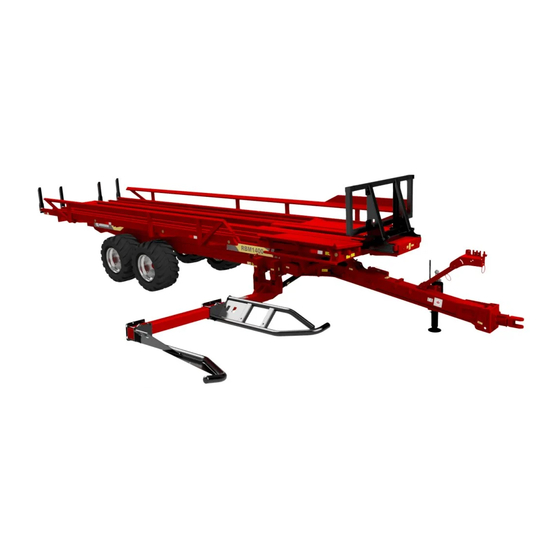
1 Introduction Congratulations! You have just acquired an Anderson self-loading trailer, a quality machine designed specifically for handling round bales. 1.1 Overview The following figures show the main components of the RBM1400, RBM2000 and RBM2000S trailer models. Figure 1 — Main Components of the Self-Loading Trailers 1.2 Technical specifications... - Page 14 Total width with arm extended (G) 5.54 m (218 in.) Maximum height when unloading (H) 3.45 m (136 in.) Tare weight 5,508 kg (12,145 lb.) GVWR (gross vehicle weight rating) 19,000 kg (41,888 lb.) Operator's Manual – Self-Loading Trailer Anderson Group...
- Page 15 Dimensions: 550/45-22.5 Recommended pressure: 3.2 bar (45 psi) Required tractor 100 hp (minimum) Minimum tractor hydraulic flow: 38 Lpm (10 gpm) Minimum tractor hydraulic pressure: 172 bar (2,500 psi) 3 dual-effect hydraulic control systems Anderson Group Self-Loading Trailer – Operator's Manual...
- Page 16 Total width with arm extended (G) 5.54 m (218 in.) Maximum height when unloading (H) 4.78 m (188 in.) Tare weight 5,828 kg (1,285 lb.) GVWR (gross vehicle weight rating) 19,000 kg (41,888 lb.) Operator's Manual – Self-Loading Trailer Anderson Group...
- Page 17 Recommended pressure: 3.2 bar (45 psi) Required 130 hp (minimum) tractor Minimum tractor hydraulic flow: 38 Lpm (10 gpm) Minimum tractor hydraulic pressure: 172 bar (2,500 psi) 2 dual-effect hydraulic control systems (RBM2000) 4 dual-effect hydraulic control systems (RBM2000S) Anderson Group Self-Loading Trailer – Operator's Manual...
-
Page 18: Options
You can record the identification information of your equipment in Figure 4. Used when the tractor has only two hydraulic systems. This valve allows you to control the pusher and unloading functions on the same oil outlet. Operator's Manual – Self-Loading Trailer Anderson Group... -
Page 19: Safety And Maintenance Pictograms
Table 6 — Safety and Maintenance Pictograms Pictogram Meaning Warning! Check the tightening torque on the lug nuts. Lubricate with grease at the frequency recommended in section 7.2. Lubricate with oil at the frequency recom- mended in section 7.1. Anderson Group Self-Loading Trailer – Operator's Manual... - Page 20 Keep a safe distance away. Warning! Before doing any maintenance or repairs, turn off the engine, remove the key from the ignition, and refer to chapter 7 Maintenance. Warning! Pressurized hydraulic hoses. See chapter 7 Maintenance. Operator's Manual – Self-Loading Trailer Anderson Group...
- Page 21 Risk of being caught in the drive chains. Do not open or remove the guard when the engine is running. Warning! Never climb on the conveyors or the equipment when it is operating. Anderson Group Self-Loading Trailer – Operator's Manual...
- Page 22 Warning! Components must be locked dur- ing transport. Warning! Disengage the handbrake before moving the trailer. Maximum speed of 25 km/h (15 mph). Adjust the forks before beginning a load (see section 4.4). Operator's Manual – Self-Loading Trailer Anderson Group...
-
Page 23: Safety Precautions
2 Safety precautions Your Anderson trailer was designed to minimize risk to the operator. Nevertheless, it must only be used for its intended purpose. Misuse of the trailer may result in injury to the operator. The trailer has a hydraulic system and moving mechanical parts. All these parts may cause serious and even fatal injuries to people and animals. - Page 24 Ensure that the warnings and pictograms remain clean and clearly visible. In the event of damage, ask your manufacturer (or dealer) for new labels. During repairs, ensure that any replacement parts bear the same labels as the original parts. Operator's Manual – Self-Loading Trailer Anderson Group...
-
Page 25: Safety Tips For Transport
Check the maximum allowable height and width and whether the load must be attached. NOTE: The trailer’s standard tires are generally not prescribed for long distances on public roads. Anderson Group Self-Loading Trailer – Operator's Manual... - Page 26 Completely close the bale guides and adjustable support for 1.8 m (6 ft.) bales (Details A and Insert the loading arm locking pin (Detail B). Close the ball valve for the unloading cylinders (Detail C). Figure 5 — Safety Tips for Transport Operator's Manual – Self-Loading Trailer Anderson Group...
-
Page 27: Safety Tips For Hitching
Always keep the equipment and its accessories in perfect condition. Keep the oil tanks clean. Follow the maintenance intervals. Before beginning work: Turn off the engine and remove the key from the ignition; Put the gearshift in neutral and apply the handbrake; Anderson Group Self-Loading Trailer – Operator's Manual... - Page 28 Before repressurizing the hydraulic lines, ensure that all the couplings are correctly tightened. Check the hydraulic lines regularly and replace them if they are damaged. The replacement lines must meet the manufacturer's technical requirements. Operator's Manual – Self-Loading Trailer Anderson Group...
-
Page 29: Waste Recovery
Return used fluids to a collection and reprocessing centre so that they are recycled or disposed of in accordance with legislation. Stockpiling, abandoning or dumping tires is prohibited, as is burning them outdoors. Return them to an approved distributor or collector. Anderson Group Self-Loading Trailer – Operator's Manual... -
Page 31: Getting Started
6. Remove the wheel chocks and disengage the trailer handbrake (if applicable). To unhitch the equipment: 1. Position the equipment on a level and stable surface, turn off the tractor engine and relieve the pressure in the hydraulic hoses. Anderson Group Self-Loading Trailer – Operator's Manual... - Page 32 Figure 6 — Hitching to the Tractor Figure 7 — Hydraulic Jack Extended (A) and in Transport Position (B) NOTE: If driving on public roads, comply with all local identification and lighting regulations. Operator's Manual – Self-Loading Trailer Anderson Group...
-
Page 33: Connecting The Hydraulic And Electrical Systems
Relieve the pressure in the tractor's hydraulic system and ensure that the couplings are clean before connecting them to the tractor. Dirt will contaminate the hydraulic oil. The recommended oil flow rate is 38 Lpm (10 US gpm). Anderson Group Self-Loading Trailer – Operator's Manual... - Page 34 RBM2000S 2. On the RBM2000, connect the 12 V power source directly to the terminal block or COBO plug inside the tractor. The cable powers the electrical/hydraulic controls and the trailer control interface. Operator's Manual – Self-Loading Trailer Anderson Group...
- Page 35 4. Plug the rear lights into the 7-pin socket on the tractor. 5. Check that the tractor and trailer turn signals correspond to one another. 6. Test the hydraulic controls one by one to check that the hoses are connected properly. Anderson Group Self-Loading Trailer – Operator's Manual...
-
Page 37: Adjustments
(Figure 8, B) is greater than 50 mm (2 in.), you will need to adjust the height of the hitch. NOTE: Take the measurements on a level surface when the trailer is empty and unhitched. Anderson Group Self-Loading Trailer – Operator's Manual... -
Page 38: Adjusting The Jack Height
The jack height is adjustable. Select the position that is most suitable for the tractor drawbar. To adjust the jack height: 1. Hitch the trailer to the tractor. 2. Remove the mounting bolts from the jack. 3. Slide the jack to the desired height. Operator's Manual – Self-Loading Trailer Anderson Group... - Page 39 NOTE: In transport mode, the jack must be folded up and the lever must be placed on its support (Figure 9). Figure 9 — Hydraulic Jack Extended (A) and in Transport Position (B) Anderson Group Self-Loading Trailer – Operator's Manual...
-
Page 40: Adjusting The Bale Guides
Figure 10 — Position of the Bale Guides Table 8 — Position of the Bale Guides Based on Bale Diameter Position Bale diameter For transport 1.22 m (4 ft.) 1.37 m (4.5 ft.) Operator's Manual – Self-Loading Trailer Anderson Group... -
Page 41: Adjusting The Forks
4. Put the forks in the desired position (see Figure 12 and Table 9). 5. Put the A and B bolts back in. 6. Tighten the A, B and C bolts. Figure 11 — Adjusting the Forks Anderson Group Self-Loading Trailer – Operator's Manual... - Page 42 Position of bolt A on the inner Position of bolt A on the outer diameter fork fork 1.22 m (4 ft.) 1.35 m (4.5 ft.) 1.52 m (5 ft.) 1.65 m (5.5 ft.) 1.83 m (6 ft.) Operator's Manual – Self-Loading Trailer Anderson Group...
-
Page 43: Adjusting The Front Stopper (Rbm2000 And Rbm2000S)
Table 10 — Position of the Front Stopper Based on Bale Diameter Position Bale diameter 1.2 m (4 ft.) 1.35 to 1.5 m (4.5 to 5 ft.) 1.65 to 1.8 m (5.5 to 6 ft.) Anderson Group Self-Loading Trailer – Operator's Manual... -
Page 44: Adjusting The Pusher Travel
To adjust the spacing for the RBM2000, adjust the position of the LS_PO_R sensor that detects when the pusher is at the front of the trailer. Figure 14 — Adjusting the Pusher Travel on the RBM2000 Operator's Manual – Self-Loading Trailer Anderson Group... - Page 45 For bales 1.4 m (4 ft.) in length, install the two stoppers (Figure 15, Detail B). For bales 1.5 m (5 ft.) in length, store the two stoppers on the pusher (Figure 15, Detail A). Figure 15 — Adjusting the Pusher Travel on the RBM1400 and RBM2000S Anderson Group Self-Loading Trailer – Operator's Manual...
-
Page 46: Adjusting The Bale Retaining Support
(see "Adjusting the forks" on page 41). If the fork is not adjusted properly, it could collide with the support. Figure 16 — Adjusting the Bale Retaining Support Operator's Manual – Self-Loading Trailer Anderson Group... - Page 47 Table 12 — Adjusting the Bale Retaining Support Based on Bale Diameter Position Bale diameter Auxiliary support lowered 1.2 to 1.5 m (4 to 5 ft.) Auxiliary support raised 1.6 m (5.5 ft.) Auxiliary support raised and support extended 1.8 m (6 ft.) Anderson Group Self-Loading Trailer – Operator's Manual...
-
Page 49: Operation
They are only used for diagnostics and troubleshooting. (RBM2000 only) See chapter 6 Troubleshooting to learn which part is activated by each hydraulic lever. Figure 17 — RBM2000 Fingertip Joystick Table 13 describes the various Fingertip joystick controls. Anderson Group Self-Loading Trailer – Operator's Manual... -
Page 50: Loading Bales
Make sure the necessary adjustments have been made before you start loading bales. See chapter 4 Adjustments. Bales are loaded and positioned using the tractor's hydraulic controls or the Fingertip joystick (see "Controls" on page 49). Operator's Manual – Self-Loading Trailer Anderson Group... - Page 51 Using the outer fork to align bales allows the operator to drive the tractor further from the bales. Using the inner fork gives the operator a better view of the fork. Figure 18 — Aligning Bales in the Loading Grabber Anderson Group Self-Loading Trailer – Operator's Manual...
- Page 52 6. When the pusher reaches the end of its travel, bring it back. 7. Repeat steps 1 to 8 for each row of bales until the trailer is full. Figure 19 — Position of the Bales on the Trailer (RBM2000 and RBM2000S) Operator's Manual – Self-Loading Trailer Anderson Group...
- Page 53 When the first bales that were loaded reach the very back of the trailer, the full load indicator will show that the trailer is full (Figure 20). Figure 20 — Full Load Indicator Anderson Group Self-Loading Trailer – Operator's Manual...
-
Page 54: Unloading Bales
The pusher can be stopped from automatically moving at any time by pressing the Fingertip joystick once in either direction. 4. When all the bales have been unloaded, make the platform horizontal and bring the pusher back to the front. Operator's Manual – Self-Loading Trailer Anderson Group... -
Page 55: Troubleshooting
The hydraulic controls must never be used if the trailer can be put in motion. Before using the hydraulic controls, ensure that no one will operate the controls at the same time on the tractor. Figure 21 — Hydraulic Controls Anderson Group Self-Loading Trailer – Operator's Manual... - Page 56 Table 14 — Hydraulic Control Functions Function Description Moves the pusher forward ( ) and backward ( ) Raises ( ) and lowers ( ) the loading arm Extends ( ) and retracts ( ) the loading arm Operator's Manual – Self-Loading Trailer Anderson Group...
-
Page 57: Sensors (Rbm2000)
Detects when the loading arm is at a 45° angle LS_PO_M Detects when the pusher is in the middle position LS_PO_R Detects when the pusher is in the forward position Figure 22 — Sensor Locations Anderson Group Self-Loading Trailer – Operator's Manual... -
Page 58: Common Problems
The unloading plat- The hydraulic hoses have not Check that the hydraulic hoses are form is not moving. been connected to the tractor connected properly. properly. The ball valve is closed. Open the ball valve. Operator's Manual – Self-Loading Trailer Anderson Group... - Page 59 The arm is at less than a 45° Raise the arm to 45°. angle. For any other problems, please contact your dealer or our technical service department. Anderson Group Self-Loading Trailer – Operator's Manual...
-
Page 61: Maintenance
Before doing any repairs, maintenance or cleaning, turn off the tractor engine and remove the key from the ignition. Never perform maintenance while the machine is running. Dispose of used oil and filters in accordance with current standards. Anderson Group Self-Loading Trailer – Operator's Manual... - Page 62 3. Insert the locking pin in the hole and insert the cotterpin to keep it in place. 4. Slowly lower the platform until its weight is resting on the stand. Figure 24 — Setting Up the Safety Stand Operator's Manual – Self-Loading Trailer Anderson Group...
-
Page 63: Maintenance Schedule
Table 17 — Maintenance Schedule Remove any accumulated section debris (hay, dust, 7.10 etc.) Check tire pressure section Check that the lug nuts are tight section Check that the hubcaps section attached securely Anderson Group Self-Loading Trailer – Operator's Manual... - Page 64 Adjust the brake slack section Grease the cyl- inder joints section Grease the tan- dem axle pivots section Grease the draw- bar pivot (1) section Grease the bear- ings section Operator's Manual – Self-Loading Trailer Anderson Group...
-
Page 65: Greasing
Your self-loading trailer must be lubricated using a gun in various places indicated by the sticker in the following figure: Figure 25 – Lubrication point marker NOTE: Anderson Group recommends using synthetic grease. Anderson Group Self-Loading Trailer – Operator's Manual... - Page 66 Tandem axle pivots (4) Drawbar pivot (1) All other pivots (7) All cylinder joints (10) All bearings (6) All chains (3) Every 6 months Wheel bearings (4) Figure 26 — Platform Greasing Points Operator's Manual – Self-Loading Trailer Anderson Group...
- Page 67 Figure 27 — Greasing Points at the Front of the Trailer Anderson Group Self-Loading Trailer – Operator's Manual...
- Page 68 Figure 28 — Pusher Greasing Points Operator's Manual – Self-Loading Trailer Anderson Group...
- Page 69 Figure 29 — Loading Arm Greasing Points (RBM2000 and RBM2000S) Figure 30 — Greasing Points at the Rear of the Trailer Anderson Group Self-Loading Trailer – Operator's Manual...
-
Page 70: Adjusting The Pusher Chain Tension
3. Tighten the eight (8) bolts securing the ball bearings (A, Figure 31). Figure 31 — Adjusting the Pusher Chain Tension Operator's Manual – Self-Loading Trailer Anderson Group... -
Page 71: Adjusting The Pusher Transmission Chain Tension
2. Tighten the two (2) tension bolts on the side of the transmission (B, Figure 32) until the correct tension is reached. 3. Tighten the four (4) bolts underneath the transmission (A, Figure 32). Figure 32 — Adjusting the Pusher Transmission Chain Tension Anderson Group Self-Loading Trailer – Operator's Manual... -
Page 72: Tire Pressure
350 (+30/0) N m (258 (+22/0) 600 mm (24 60 kg (132 lb.-ft.) in.) lb.) 1 1/16 5/8-18 270 (+20/0) N m (200 (+15/0) 450 mm (18 60 kg (132 lb.-ft.) in.) lb.) Operator's Manual – Self-Loading Trailer Anderson Group... - Page 73 Regularly check that the hubcaps are firmly in place and are in perfect condition. Immediately replace missing or damaged hubcaps to prevent dirt from getting inside a hub, which could damage the bearings. Anderson Group Self-Loading Trailer – Operator's Manual...
- Page 74 1. Lift the axle until the wheel is no longer resting on the ground. For large wheels, remove the wheel to make it easier to feel the play and see what you are adjusting. 2. Remove the hubcap. 3. Remove the cotter pin or hair pin clip from the castle nut. Operator's Manual – Self-Loading Trailer Anderson Group...
- Page 75 10. Put the wheel back on (see "Assembling and attaching the wheels" on page 72 and "Tightening the lug nuts" on page 73). Once the wheel is back on, turn it slightly. The wheel should come to rest with a slight rocking movement. Figure 35 — Wheel Bearing Anderson Group Self-Loading Trailer – Operator's Manual...
- Page 76 To remove the wheel bearings (for cleaning and inspection) (see Figure 35 and Figure 36): 1. Loosen the lug nuts. 2. Lift the axle until the wheel is no longer resting on the ground. Operator's Manual – Self-Loading Trailer Anderson Group...
- Page 77 7. Apply a generous coat of grease to the cage and rollers of the small bearing, and put the small bearing on the spindle. Anderson Group Self-Loading Trailer – Operator's Manual...
- Page 78 9. Lock the castle nut with a new cotter pin or the hair pin clip, as appropriate. 10. For hubs without grease retainers, fill the hubcap with grease. 11. Put the hubcap back on. Figure 36 — Disassembling a Wheel Bearing Figure 37 — Reassembling a Wheel Bearing Operator's Manual – Self-Loading Trailer Anderson Group...
- Page 79 If the axle has a grease retainer, first put the retainer in its housing (in the correct direction). Make sure it is centred and remains in place throughout the process of putting the outer race back in. 4. Perform a final check. Anderson Group Self-Loading Trailer – Operator's Manual...
-
Page 80: Maintaining And Adjusting The Brakes (Available As An Option)
Check that the service and parking brakes are working properly. Check that the screws and nuts are tight (covers, fulcrum...) and that the cotter pins, pins, retaining rings, etc. are secured. Check for any oil or air leaks. Operator's Manual – Self-Loading Trailer Anderson Group... - Page 81 (brake levers have multiple holes). If a slack adjuster has been installed, turn the adjusting screw on the slack adjuster to adjust its relative position to the cam bearing (see Figure 41). Anderson Group Self-Loading Trailer – Operator's Manual...
- Page 82 See "Adjusting the wheel bearing play" on page 74 and "Lubricating the wheel bearings" on page 76 for how to disassemble and reassemble the wheel hub, as well as how to grease and adjust the play of the wheel bearings. During this process, inspect all the brake mechanisms: Operator's Manual – Self-Loading Trailer Anderson Group...
- Page 83 (see Figure 42). The shoes will then make contact with the drum. 2. Tighten the anchor pin while maintaining pressure on the lever. 3. Replace the pin if using a cotter pin. Figure 42 — Centring the Brake Shoes Anderson Group Self-Loading Trailer – Operator's Manual...
-
Page 84: Maintaining The High-Pressure Filter (Rbm2000)
If it is red, it must be replaced. NOTE: If your filter does not have an indicator, remove the filter in order to inspect the cartridge and replace it if needed. Figure 43 — High-Pressure Filter Operator's Manual – Self-Loading Trailer Anderson Group... -
Page 85: Maintaining The Hydraulic Jack
If you do not plan on using the trailer for a long time, store it on a flat surface.For your safety, chock the wheels to prevent the trailer from moving. NOTE: Anderson Group strongly recommends cleaning and performing general maintenance on the machine before storing it for long periods. NOTE: Before putting the trailer in storage, ensure that all the cylinders have been retracted to prevent premature wear and tear on their rods and seals. - Page 87 ANDERSON GROUP 5125 De la Plaisance Chesterville, QC G0P 1J0 CANADA Email: service@grpanderson.com Phone: 1-819-382-2952 Fax: 1-819-382-2218 www.grpanderson.com...
Need help?
Do you have a question about the RBM Series and is the answer not in the manual?
Questions and answers