
Related Manuals for Elma Elmasonic S Series


Summary of Contents for Elma Elmasonic S Series
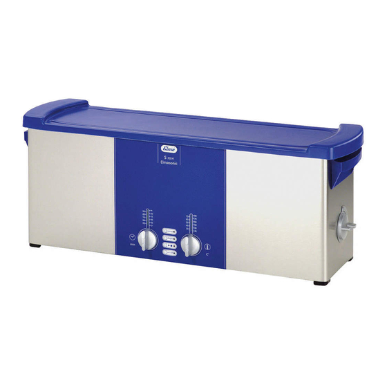
- Page 1 Service Manual Elmasonic S Ultrasonic Cleaning Units English Elma Schmidbauer GmbH Gottlieb-Daimler-Str. 17 D-78224 Singen Fon +49 ( )7731 / 882-0 Fax +49 ( )7731 / 882-266 info@elma-ultrasonic.com www.elma-ultrasonic.com...
-
Page 2: Table Of Contents
Elmasonic S 10 (H) – S 300 (H) ......28 8.1.1 Electric connections ..........28 8.1.2 How to remove the PCB control ......28 8.1.3 How to mount the PCB control ......29 Elmasonic S350R | S450H | S500HM | S900H ..31 8.2.1 Electric connections ..........31 SM_Elmasonic_S_02.2018_EN © Elma Schmidbauer GmbH... - Page 3 How to fill cleaning liquid .........64 18.2 Cleaning media ............65 18.3 Heating of the cleaning liquid ........65 18.4 Check ultrasound ............65 Putting out of operation and disposal ....67 Manufacturer contact address ....... 67 Conclusion ............. 67 © Elma Schmidbauer GmbH SM_Elmasonic_S_02.2018_EN...
-
Page 4: General
Please observe the important safety warnings (section 2), and the information on initial operation (section 17). In case of any further queries ELMA will be glad to assist. For our technical support and contact address please see the last page. -
Page 5: Demands On The Service Staff
The following items are required for arranging an ESD protected workplace: Room ESD work pad; ESD floor surface; Tools Staff ESD earthing connection from the wrist of the person to the work pad; ESD shoes Packing ESD protective bag; ESD boxes / cartons © Elma Schmidbauer GmbH SM_Elmasonic_S_02.2018_EN... -
Page 6: Important Safety Warnings
CE conformity faulty parts must be replaced by original spare parts only. Exclusion of liability The manufacturer cannot be held liable for damages on persons, on the unit or on the workshop equipment caused by improper use or wrong repair. SM_Elmasonic_S_02.2018_EN © Elma Schmidbauer GmbH... -
Page 7: Organizational Details
New units The limitation period of warranty claims is 2 years (from the date of purchase). If no proof of purchase can be produced, Elma can find out the date of manufacturing by means of the serial number (nameplate). Repair Elma grant a limitation period of 2 years on all exchange parts and on any repair works carried out. -
Page 8: How To Find Out The Year Of Manufacturing
The second and third figures (B) – starting from the right – represent the month. • The first figure (A) – starting from the right – represents the year. Example: S/N 1 0 4 8 0 0 0 4 5 April 2015 SM_Elmasonic_S_02.2018_EN © Elma Schmidbauer GmbH... -
Page 9: Product Description
Turning knob for draining the transducer tank (on Elmasonic S 30 and larger) Vertical position: drain open Horizontal position: drain shut. Operating elements for the control of the unit functions description see sections 4.2 and 4.3. © Elma Schmidbauer GmbH SM_Elmasonic_S_02.2018_EN... -
Page 10: Description Operating Elements S 15 - S 900 H
Ultrasound LED Not on Elmasonic S 10 / S 10 H. Key on/off for switching the unit on and off. On/off LED * setting of the required value: turn clockwise reset: turn anti-clockwise SM_Elmasonic_S_02.2018_EN © Elma Schmidbauer GmbH... -
Page 11: Description Operating Elements S 10 | S 10 H
4.3 View operating elements Elmasonic S 10 H Functions as on Elmasonic S 30 – S 900 H with the following exceptions: Ultrasound LED indicates ultrasonic operation Temperature LED (on units with heating) indicates heating operation © Elma Schmidbauer GmbH SM_Elmasonic_S_02.2018_EN... -
Page 12: Technical Details
* S 10 – S 15 H: Impulse sound; S 30 – S 900 H: Double half-wave sound. The form of signal has been adapted to the geometry of the transducer tank. Depending on the form of signal the peak of the ultrasonic power is 4 or 8-fold. SM_Elmasonic_S_02.2018_EN © Elma Schmidbauer GmbH... -
Page 13: Operating And Display Functions
S 15 H – S 900 H: LED set period flashes LED ultrasound is turned on when set temperature is reached LED set period is turned on LED remaining period flashes © Elma Schmidbauer GmbH SM_Elmasonic_S_02.2018_EN... - Page 14 * Sweep and degas ■ press ► cannot be operated at the LED sweep is turned same time press Sweep key S 15 – S 900 H: LED set temperature is turned on LED remaining period flashes SM_Elmasonic_S_02.2018_EN © Elma Schmidbauer GmbH...
- Page 15 LED degas flashes function* in Auto-Degas mode LED ultrasound is keep Degas key * Sweep and Degas for 10 minutes and turned on pressed (> 2 sec.) cannot be operated at the switches off same time subsequently © Elma Schmidbauer GmbH SM_Elmasonic_S_02.2018_EN...
-
Page 16: Circuit Diagram Elmasonic S 10 (H) - S 300 (H)
Product description Circuit diagram Elmasonic S 10 (H) – S 300 (H) SM_Elmasonic_S_02.2018_EN © Elma Schmidbauer GmbH... -
Page 17: Circuit Diagram Elmasonic S 450 H | S 500 Hm
Product description Circuit diagram Elmasonic S 450 H | S 500 HM © Elma Schmidbauer GmbH SM_Elmasonic_S_02.2018_EN... -
Page 18: Circuit Diagram Elmasonic S 350 R | S 900 H
Product description Circuit diagram Elmasonic S 350 R | S 900 H SM_Elmasonic_S_02.2018_EN © Elma Schmidbauer GmbH... -
Page 19: Trouble Shooting
S 15 – S 900 H: LED display heating temperature flashes fast („running light“) / LED display in the ultrasound key flashes fast: There is a fault in the temperature measuring, e.g. interrupted connection to temperature gauge or a faulty gauge. © Elma Schmidbauer GmbH SM_Elmasonic_S_02.2018_EN... -
Page 20: Measuring Points On The Pcbs
Mains input voltage before fuse (mains voltage!) Voltage supply heating element(s) (mains voltage!) Voltage supply PCB control (mains voltage!) Measuring points interference filter S 10 – S 300 manufactured 11.2005 or later Illustration 5.2. Measuring points PCB interference filter SM_Elmasonic_S_02.2018_EN © Elma Schmidbauer GmbH... - Page 21 For measuring pull off contact: At 25 °C approx. 10 kOhm Measuring points triac (outside connections). At a measured resistance below 100 Ohm the triac is faulty. Illustration 5.4. Measuring points triac (here PCB control S10H) © Elma Schmidbauer GmbH SM_Elmasonic_S_02.2018_EN...
-
Page 22: How To Open The Unit
1. Pull the mains plug! 2. Place the unit onto the workplace upside down. 3. Carefully lever the bottom plate loose with a screw driver or a similar tool (illustration 6.1.). Illustration 6.1. Levering of the bottom plate SM_Elmasonic_S_02.2018_EN © Elma Schmidbauer GmbH... -
Page 23: Elmasonic S30, S 40, S 70, S 80 (H)
4. Remove the 4 plastic rivets (illustration 6.3.B) at both lateral plastic parts (illustration 6.3.C) by levering with a knife. Part: No. for orders: 1045474. 5. Remove the 2 lateral plastic parts (illustration 6.3.C). 6. Remove the bottom plate. © Elma Schmidbauer GmbH SM_Elmasonic_S_02.2018_EN... -
Page 24: Elmasonic S 60, S 100 - S 900 H
4. Unscrew the two visible recessed head screws. 5. Carefully lever the bottom plate loose with a screw driver or a similar tool illustration 6.1.). Ilustration 6.3. Unscrew the two recessed head screws and the 4 unit feet SM_Elmasonic_S_02.2018_EN © Elma Schmidbauer GmbH... -
Page 25: How To Close The Unit / Mount The Bottom Plate
How to close the unit / Mount the bottom plate Follow the instructions on opening the unit in reverse order. Ensure that all electric wires are connected correctly and no electric wires are pinched by the bottom plate before you close the unit. © Elma Schmidbauer GmbH SM_Elmasonic_S_02.2018_EN... -
Page 26: How To Remove / Replace The Turning Knobs
How to proceed Pull off the turning knob exactly square to the unit. Illustration 7.1. Pull off the turning knob Illustration 7.2. View turning knob SM_Elmasonic_S_02.2018_EN © Elma Schmidbauer GmbH... -
Page 27: How To Mount The Turning Knobs
Put the turning knob square onto the unit. Ensure that the turning knob is positioned correctly: The cog of the turning knob (A) must correspond with the stop position on the PCB support (B). Illustration 7.4. Put on the turning knob © Elma Schmidbauer GmbH SM_Elmasonic_S_02.2018_EN... -
Page 28: How To Replace The Pcb Control
PCB control by tilting it to the inside. 4. Separate the electric plug connections and take the PCB control out of the unit. Note: All plug connections are coded and cannot be interchanged. SM_Elmasonic_S_02.2018_EN © Elma Schmidbauer GmbH... -
Page 29: How To Mount The Pcb Control
3. Clip the correctly positioned PCB control into the upper fastening clips (see illustration 8.2. / 8.3.). 4. Mount the turning knobs as described in section 7.2. 5. Close the bottom plate as described in section 6.4. © Elma Schmidbauer GmbH SM_Elmasonic_S_02.2018_EN... - Page 30 How to replace the PCB control Illustration 8.4. Electric connections on PCB control Connection for temperature gauge Connection for fan (on S120H and larger) Voltage supply PCB / voltage supply heating element(s) (mains voltage) Connections transducer system(s) (high frequency) SM_Elmasonic_S_02.2018_EN © Elma Schmidbauer GmbH...
-
Page 31: Elmasonic S350R | S450H | S500Hm | S900H
(mains voltage) Connections control line to power module 8.2.2 How to remove the PCB control Follow the instructions given in section 8.1. 8.2.3 How to mount the PCB control Follow the instructions given in section 8.2. © Elma Schmidbauer GmbH SM_Elmasonic_S_02.2018_EN... -
Page 32: Power Module S350R | S450H | S500Hm | S900H
Illust. 8.7. Connections of the master power module on S350R|S900H Connection control line to slave power module (on S350 R| S900 H). Voltage supply PCB connection to slave power module (on S 350 R | S 900 H). SM_Elmasonic_S_02.2018_EN © Elma Schmidbauer GmbH... -
Page 33: How To Replace The Pcb Interference Filter
Illustration 9.1. Connections PCB interference filter Connections for heating element (mains voltage) on units with heating. Polarization of the cables is irrelevant. Connections to PCB control (mains voltage). Polarization of the cables is irrelevant. © Elma Schmidbauer GmbH SM_Elmasonic_S_02.2018_EN... - Page 34 How to replace the PCB interference filter Illustration 9.2. Circuit diagram version before 10.2005 Illustration 9.3. Arrangement version before 10.2005 SM_Elmasonic_S_02.2018_EN © Elma Schmidbauer GmbH...
- Page 35 10.2005. This is no longer necessary. The heating element(s) is/are now directly connected to the plug contacts on the PCB interference filter. Illustration 9.4. Circuit diagram version 11.2005 and later Illustration 9.5. Arrangement version 11.2005 and later © Elma Schmidbauer GmbH SM_Elmasonic_S_02.2018_EN...
-
Page 36: How To Remove The Pcb Interference Filter
3. Connect the electric plug connections to the plug contacts. Ensure that all connections are plugged correctly. 4. Check again if all contacts and positioning of PCB are correct. Close the bottom plate as described in section 6.4. SM_Elmasonic_S_02.2018_EN © Elma Schmidbauer GmbH... - Page 37 How to replace the PCB interference filter Illustration 9.7. Electric connections Voltage supply for PCB control (black | white). Not connected Connection for heating control (grey). Connection for heating direct (white). Illustration 9.8. Electric connections heater (perspective view) © Elma Schmidbauer GmbH SM_Elmasonic_S_02.2018_EN...
-
Page 38: Elmasonic S 60 (H) - S 100 (H)
Connection for heating element(s) (mains voltage). On units with more than one heating element, the heating elements are connected to plug distribution contacts. Polarization of the cables is irrelevant. Connections to PCB control (mains voltage). Polarization of the cables is irrelevant. SM_Elmasonic_S_02.2018_EN © Elma Schmidbauer GmbH... - Page 39 How to replace the PCB interference filter Illustration 9.11. Circuit diagram version before 10.2005 Illustration 9.12. Arrangement plan version before 10.2005 © Elma Schmidbauer GmbH SM_Elmasonic_S_02.2018_EN...
- Page 40 10.2005. This is no longer necessary. The heating element(s) is/are now directly connected to the plug contacts on the PCB interference filter. Illustration 9.13 Circuit diagram version of 11.2005 or later Illustration 9.14. Arrangement plan version of 11.2005 or later SM_Elmasonic_S_02.2018_EN © Elma Schmidbauer GmbH...
-
Page 41: How To Remove The Pcb Interference Filtern
PCB interference filter (illustration 9.18. / illustration 9.19.B and D). 4. Check again if all contacts and positioning of PCB are correct. 5. Close the bottom plate as described in section 6.4. © Elma Schmidbauer GmbH SM_Elmasonic_S_02.2018_EN... - Page 42 Connections for 1 – 3 heating elements (underneath the PCB). All contacts are bridged and have the same potential: One cable per heating element is connected. Illustration 9.19. Electric connections with 2 heating elements (e.g. S 40 H) SM_Elmasonic_S_02.2018_EN © Elma Schmidbauer GmbH...
-
Page 43: Elmasonic S 120 (H) - S 300 (H)
10.2005. This is no longer necessary. It is now easier to leave the plug distributors unused and to connect each cable on on of the connections indicated in illustration 9.23.C and D. © Elma Schmidbauer GmbH SM_Elmasonic_S_02.2018_EN... -
Page 44: How To Remove The Pcb Interference Filter
PCB interference filter (illustration 9.31.B and 4. Check again if all contacts and positioning of PCB are correct. 5. Close the bottom plate as described in section 6.4. SM_Elmasonic_S_02.2018_EN © Elma Schmidbauer GmbH... - Page 45 Connections for heating control (black/grey). Polarization of the cables is important. Connections for up to 6 heating elements. All contacts are bridged and have the same potential: One cable per heating element is connected. © Elma Schmidbauer GmbH SM_Elmasonic_S_02.2018_EN...
-
Page 46: Elmasonic S350R | S450H | S500Hm | S900H
Voltage supply heating control (phase) >> plug PCB control Voltage supply power module(s) (phase) >> plug PCB power module(s) Voltage supply power module(s) (Zero) >> plug PCB control Voltage supply ultrasound control (Zero) >> plug PCB control H - I Fastening screws SM_Elmasonic_S_02.2018_EN © Elma Schmidbauer GmbH... - Page 47 Version 02.2006 and later Illustration 9.26. Connections PCB interference filter S 350 R / S 450 H / S 900 H Illustration 9.27. Circuit diagram version before/after 2.2006 Illustration 9.28. Arrangement plan version before/after 2.2006 © Elma Schmidbauer GmbH SM_Elmasonic_S_02.2018_EN...
-
Page 48: How To Remove The Pcb Interference Filter
2. Connect the electric plug connections to the contacts. Ensure that all connections are plugged correctly (illustration 9.26.A-G). 3. Check again if all contacts and positioning of PCB are correct. 4. Close the bottom plate as described in section 6.4. SM_Elmasonic_S_02.2018_EN © Elma Schmidbauer GmbH... -
Page 49: How To Replace The Potentiometers
How to replace the Potentiometers How to replace the Potentiometers The units of the Elmasonic S series are no longer fitted with mechanical switch elements as the units of the previous series Transsonic, but with electronic switch elements. Setting of the cleaning period and the temperature is carried out via potentiometer which are soldered to the PCB control. -
Page 50: How To Replace The Front Panel
1. Pull off the turning knobs as described in section 7. 2. Carefully pull off the front panel (see illustration 11.1.). 3. Put on the new adhesive front panel. 4. Mount the turning knobs. Illustration 11.1. Pull off the front panel. (Illustration with open unit) SM_Elmasonic_S_02.2018_EN © Elma Schmidbauer GmbH... -
Page 51: How To Replace The Pcb Support
9. Mount the bottom plate; close the unit. Ensure that all plug contacts are plugged correctly and that no cable is pinched. Illustration 12.1. Pull out / push the PCB support vertically into the housing © Elma Schmidbauer GmbH SM_Elmasonic_S_02.2018_EN... -
Page 52: How To Replace The Heating
6. Use a file to round off the two edges of the aluminum profile of the new heating element where it will enter the supporting rails. 7. Carefully push the heating element into the supporting rails. 8. Secure the heating element against displacement with silicone. SM_Elmasonic_S_02.2018_EN © Elma Schmidbauer GmbH... - Page 53 Push it into the supporting rails, be careful not to jam the heating element. Then secure against displacement with silicone. Tank unremoved S15H – S 300H Illustration 13.2. Transducer tank unremoved, with horizontally mounted heating element. Broken line: cut the silicone to remove. © Elma Schmidbauer GmbH SM_Elmasonic_S_02.2018_EN...
- Page 54 Insert the new heating element (position C) into the supporting rails. Push it into the supporting rails, be careful not to jam the heating element. Then secure against displacement with silicone. SM_Elmasonic_S_02.2018_EN © Elma Schmidbauer GmbH...
-
Page 55: Heating Wiring S 450 H And S 900 H
S 900 H: Connection mains voltage (zero) to terminal distributor of heating on the other side of the transducer tank S 900 H: Connection mains voltage (phase) switched to terminal distributor of the heating on the other side of the transducer tank © Elma Schmidbauer GmbH SM_Elmasonic_S_02.2018_EN... -
Page 56: Replacement Of Piezo-Ceramics
Replacement of piezo-ceramics Replacement of piezo-ceramics The piezo-ceramics must be replaced at the factory only. If any of the transducers are damaged, the complete tank must be replaced. SM_Elmasonic_S_02.2018_EN © Elma Schmidbauer GmbH... -
Page 57: Replacement Of Transducer Tank
Cavitational erosion Illustration 15.1. Heavy cavitational erosion at the spot where the transducer system is fixed Illustration 15.2. Leaking tank floor with traces of liquid © Elma Schmidbauer GmbH SM_Elmasonic_S_02.2018_EN... - Page 58 9. Degrease and clean the glueing surfaces of the housing edge of the (new) tank with alcohol. 10. Fill new sealing material (e.g.Teroson) evenly elong the edge of the transducer tank. SM_Elmasonic_S_02.2018_EN © Elma Schmidbauer GmbH...
- Page 59 (see section 16). 14. Reconnect all electric cables. Heat up tank edge Illustration 15.3. Heat up the edge of the transducer tank with a hot air Cut the sealing Illustration15.4. Cut the sealing and lever the housing. © Elma Schmidbauer GmbH SM_Elmasonic_S_02.2018_EN...
-
Page 60: Replacement Of Drain Duct
4. Mounting: Position the new turning knob with inserted extension and fasten with the hexagon socket screw. Illustration 16.1. Open the hexagon socket screw anti-clockwise (S30 – S300H) SM_Elmasonic_S_02.2018_EN © Elma Schmidbauer GmbH... -
Page 61: How To Replace The Ball Valve
7. Remove any remains of Loctite from the thread of the drain duct and clean the thread e.g. with alcohol. 8. Clean the inner thread of the new ball valve and the ductings e.g. with alcohol. © Elma Schmidbauer GmbH SM_Elmasonic_S_02.2018_EN... - Page 62 Illustration 16.3. Open the barrel nipple with a pipe wrench. Arrest the ball valve with a fork wrench during the process. Illustration 16.4. Open the ball valve with a pipe wrench. Arrest the ball valve with a fork wrench during the process. SM_Elmasonic_S_02.2018_EN © Elma Schmidbauer GmbH...
-
Page 63: Replace The Handle
5. Fix the handle with the 2 new spilt pins: push the 2 new split pins, e.g. with a long tweezers, into the handle. 6. Fix the 2 new split pins and the handle, e.g. with silicone. © Elma Schmidbauer GmbH SM_Elmasonic_S_02.2018_EN... -
Page 64: Putting Into Operation / Trial Run
Fresh cleaning liquid is saturated with air which impairs the liquid cleaning effect of the ultrasonic activity. Sounding the liquid over a period of several minutes before the actual cleaning process is started will eliminate the microscopic air bubbles from the liquid. SM_Elmasonic_S_02.2018_EN © Elma Schmidbauer GmbH... -
Page 65: Cleaning Media
After switch-on the liquid must be degassed to remove the oxygen. With the ultrasound switched on, this takes approx. 5 – 10 minutes depending on the size of the unit. For a description of the function please see section 4.5. Operating and Display functions. © Elma Schmidbauer GmbH SM_Elmasonic_S_02.2018_EN... - Page 66 The ultrasound will tear pieces out of the sheet. The size of the torn holes indicates the zones of different cleaning intensity in the cleaning tank. It is normal that the number of holes is bigger around the transducer elements. SM_Elmasonic_S_02.2018_EN © Elma Schmidbauer GmbH...
-
Page 67: Putting Out Of Operation And Disposal
If you have problems in finding or repairing a fault we recommend to return the unit to the supplier or manufacturer for inspection and repair. Please include a short note describing the original cause of the malfunction and which repair works you have carried out. © Elma Schmidbauer GmbH SM_Elmasonic_S_02.2018_EN...
Need help?
Do you have a question about the Elmasonic S Series and is the answer not in the manual?
Questions and answers