Table of Contents
Advertisement
Quick Links
Advertisement
Table of Contents

Related Manuals for PerkinElmer TGA 8000


Summary of Contents for PerkinElmer TGA 8000
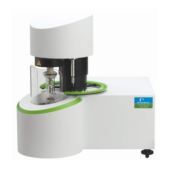
- Page 1 THERMAL ANALYSIS TGA 8000 Installation and Hardware Guide...
- Page 2 The information contained in this manual is subject to change without notice. Except as specifically set forth in its terms and conditions of sale, PerkinElmer makes no warranty of any kind with regard to this manual, including, but not limited to, the implied warranties of merchantability and fitness for a particular purpose.
-
Page 3: Table Of Contents
Warnings and Labels ....................12 Warning Label on the Upper Ring ................ 12 Warning Label behind the Furnace ............... 13 Warning Labels on the Back of the TGA 8000 ............14 Environmental Requirements for the TGA 8000 ............15 Hazardous Chemical Warnings ................16 Installation Category ................... - Page 4 4 . TGA 8000 Installation and Hardware Guide Removing the Furnace Tube ................64 Replacing the Furnace Tube ................64 Cleaning the Furnace Tube ................. 65 Replacing a Thermocouple ..................66 Furnace Hangdown Wire Maintenance ............... 69 Removing the Hangdown Wire ................69 Installing the Hangdown Wire ................
-
Page 5: Safety And Regulatory Information
Safety and Regulatory Information... -
Page 6: Symbols Used In This Manual
6 . TGA 8000 Installation and Hardware Guide Symbols Used in this Manual The Pyris installation and hardware guide contains information and warnings that must be followed by the user to ensure safe operation and to maintain the instrument(s) in a safe condition. -
Page 7: Symbols Used On The Instrument
Symbols Used on the Instrument . 7 Symbols Used on the Instrument The symbols that appear on the instruments discussed in this installation are as follows: CAUTION - Risk of Danger Sections in this manual must be consulted to determine the nature of the potential hazard and any actions which have to be taken. -
Page 8: Electrical Warnings
CAUTION: Do not attempt to make adjustments, replacements, or repairs to this instrument except as described in this manual. Only a PerkinElmer service representative should be permitted to service the instrument. ATTENTION: N'essayez pas d'effectuer des réglages, des remplacements ou des réparations sur cet appareil, sauf comme décrit dans ce manuel. -
Page 9: Electrical Safety
Be sure the power cord is the correct one for your laboratory. The TGA 8000 power cord must be rated at or better than 100/120 VAC at 15 A or 150 AC at 10 A. The line cord used must meet the National Safety Agency's guidelines for the particular country. -
Page 10: Safety Precautions For The Tga 8000
Il est conseillé de poster une copie de ces précautions sur ou près de l'instrument lui-même. WARNING: The glass parts on the TGA 8000 are fragile and may be subject to breakage if not handled carefully. -
Page 11: Specifications
• Do not attempt to move the TGA 8000 while it is on. Wait until the power is off and the furnace cooling fan has stopped spinning before moving the instrument. •... -
Page 12: Warnings And Labels
12 . TGA 8000 Installation and Hardware Guide Warnings and Labels Warning Label on the Upper Ring WARNING: Grounding circuit continuity is vital for the safe operation of equipment. Never operate equipment with the grounding connector disconnected. Disconnect supply cord before operating. -
Page 13: Warning Label Behind The Furnace
Warnings and Labels . 13 Warning Label behind the Furnace CAUTION – HOT SURFACE which indicates that the furnace at the center of the ring may be hot. ATTENTION - SURFACE CHAUD qui indique que le four au centre de l'anneau peut être chaud. -
Page 14: Warning Labels On The Back Of The Tga 8000
14 . TGA 8000 Installation and Hardware Guide Warning Labels on the Back of the TGA 8000 WARNING: Always keep airflow unobstructed. To maintain adequate ventilation, do not block the back of the instrument. AVERTISSEMENT: Toujours garder l'écoulement d'air dégagé. -
Page 15: Environmental Requirements For The Tga 8000
Environmental Requirements for the TGA 8000 . 15 Environmental Requirements for the TGA 8000 The TGA 8000 has been designed for indoor use only and should not be operated in an explosive environment. The TGA 8000 operates most efficiently under the following conditions: •... -
Page 16: Hazardous Chemical Warnings
16 . TGA 8000 Installation and Hardware Guide Hazardous Chemical Warnings Before using any chemicals or solvents with the instrument, you should be thoroughly familiar with all hazards and safe handling practices. Observe the manufacturer's recommendations for use, storage, and disposal. These recommendations are normally provided in the material safety data sheets (MSDS) supplied with the solvents. -
Page 17: Pollution Degree 2
Normally only non-conductive POLLUTION occurs. Occasionally, however, a temporary conductivity caused by condensation must be expected. South Korea Ingress Protection The TGA 8000 is rated IP20 as defined in IEC 60529. Storage Conditions The TGA 8000 may be stored under the following conditions: •... -
Page 18: Weee Instructions For Perkinelmer Products
For Customer Care telephone numbers select “Contact us” on the web page. Products from other manufacturers may also form a part of your PerkinElmer system. These other producers are directly responsible for the collection and processing of their own waste products under the terms of the WEEE Directive. -
Page 19: Prepare The Laboratory
Prepare the Laboratory... -
Page 20: Overview
About the Microbalance The microbalance of the TGA 8000 operates as a high gain electromechanical servo system that permits detection of weight changes as small as 0.1 g, with a maximum capacity of 1300 mg. - Page 21 TGA 8000. Sample Preparation The TGA 8000 can analyze solid or liquid samples. Solid samples can be in the form of film, crystal, or grains. In some cases, you may want to chop or grind the sample to create a large surface area that is exposed to the purge gas atmosphere.
- Page 22 240 V systems is +6%, –10%.) The supply must be smooth, clean, earthed and free of transient voltages over 40 V. The frequency range is +/-1% for 50 Hz and 60 Hz systems. Instrument Maximum Power Requirements: TGA 8000: 100 - 240 +/- 10%, 50/60 Hz. +/- 1%...
- Page 23 Purge Gas and Pneumatic Supply Requirements Minimally, the TGA 8000 requires a System Purge gas, also known as the balance purge. This gas must be clean and dry. System gas is controlled by a mass flow controller resident in the analyzer.
-
Page 24: Order Spares And Accessories
If you are located within the U.S., call toll free 1-800-762-4000, 8 a.m. to 8 p.m. EST. Your order will be shipped promptly, usually within 24 hours. • If you are located outside of the U.S., call your local PerkinElmer sales office. -
Page 25: Installing The Tga 8000
Installing the TGA 8000... -
Page 26: Tga 8000 Installation Summary
• Install the Furnace Hangdown Wire and Balance Tare Weight • Calibrate the TGA 8000 • Install the Cooling Jacket Accessory or the Accupik Accessory (if applicable) Instructions for installing a TGA 8000 with an autosampler are included where appropriate. -
Page 27: Unpack The Tga 8000
Unpack the TGA 8000 . 27 Unpack the TGA 8000 Each component of the TGA 8000 system comes in its own box. The system components are: • TGA 8000 • Personal Computer • Printer (optional) • Installation Kit containing the Spares Kit CAUTION: Take care when unpacking the TGA. - Page 28 28 . TGA 8000 Installation and Hardware Guide NOTE: The furnace shield is shipped in the inverted position on the furnace door. Unscrew and remove the furnace shield from the furnace door, invert it then secure it on the furnace door.
-
Page 29: Set Up Tga 8000 System Components
The Sample Gas enters through connectors (labeled Sample Gas A or Sample Gas B) on the back of the TGA 8000. It is applied as pressure 1 - 3 Bar (optimum 2 Bar). The software controls the gas flow controller to the sample area. Gas is directed to the furnace through Teflon tubing from the flow controller to an inlet port on the bottom of the Balance mounting plate. - Page 30 System purge. Connect the end of the Teflon tubing to the fitting labeled Balance Purge located on the back of the TGA 8000. Tighten the nut fingertight and then, using a wrench tighten a quarter turn past fingertight.
-
Page 31: Connect The Tga 8000 Components
Connecting Reactive Gas The TGA 8000 has a reactive gas assembly with which a reactive gas can enter the sample area. The reactive gas enter through the rear of the TGA When using corrosive reactive gas, connect it to a connector on the rear of the balance dome. -
Page 32: Configure The Tga 8000
TGA 8000 • Printer Turn on the purge gas supply, and the water for the TGA 8000 cooling system, if applicable, or any other accessories for the cooling device you are using. Configure the TGA 8000 Highlighting the TGA 8000 in Pyris Configuration dialog and clicking Edit displays the Instrument Configuration dialog. - Page 33 Click the Add Analyzer button. The Add Analyzer dialog box appears. When a TGA 8000 is connected to the PC and has been added to the Pyris software using the Add Analyzer dialog, it should be identified in the Pyris Configuration dialog.
-
Page 34: Configure The Ios App For The Tga 8000
Configure the iOS App for the TGA 8000 This procedure will help guide you in configuring the TGA 8000 for use with an iPad/iPhone. The interface is designed so the Pyris Light app communicates with the TGA8000 via the PC which is connected to your company’s network. - Page 35 Set Up TGA 8000 System Components . 35 In the Remote Control section click the Enable checkbox and select the Maximum number of devices the TGA 8000 can connect to. When complete click OK Select Remote Control from the Pyris Tools menu.
- Page 36 36 . TGA 8000 Installation and Hardware Guide Click the New Analyzer button Enter the IP Address, Port Number, and Name of the Analyzer (enter any name) then click Next. This displays the Settings screen which displays the General settings, Display...
- Page 37 Set Up TGA 8000 System Components . 37 Click Accept (these settings can be changed at any time). This displays the Main Screen displaying a list of all Analyzers. Select your analyzer and the connection will be made. This is confirmed when the...
- Page 38 38 . TGA 8000 Installation and Hardware Guide Connection can also be confirmed by observing the Remote Control dialog in Pyris which displays the Local IP address and Port of the iPad or iPhone. Connection permissions can be controlled with all devices within this dialog.
-
Page 39: Initial Setup For The Balance And Hangdown Wires
Look at the level to see if the bubble is in the center. If it is not, slowly turn the knobs of the adjustable feet until the bubble is centered in the level. The TGA 8000 is leveled when the bubble is centered inside the ring. - Page 40 Expand the iris opening by pushing the iris arm in a clockwise direction. Using tweezers, pick up the appropriate tare weight for the TGA 8000 and carefully hang it from the loop of the hangdown ribbon located on the right arm of the balance.
-
Page 41: Adjusting The Convection Iris
Initial Setup for the Balance and Hangdown Wires . 41 Adjusting the Convection Iris The iris is an anti-convection device. It prevents reaction gases from rising into the balance chamber from the furnace. CAUTION: If the iris is not adjusted properly then soot from the sample will contaminate the balance mechanism. -
Page 42: Autosampler Calibration
Replace the balance cover Autosampler Calibration CAUTION: If the TGA 8000 is moved or installed for the first time, the Initial Setup for the balance and hangdown wires must be performed prior to Autosampler Calibration to ensure reliable operation of the autosampler. - Page 43 Initial Setup for the Balance and Hangdown Wires . 43 In the Pyris Software TGA 8000 screen (located at the top of the screen) click Calibrate Autosampler from the Calibrate menu. The Autosampler Calibration dialog box is displayed: Calibrate the tray height by clicking on the Tray Vertical button and follow the on- screen prompt.
- Page 44 44 . TGA 8000 Installation and Hardware Guide Calibrate the sample pickup and drop-off position by clicking on the Tray Rotation button and follow the on-screen prompt. For this calibration an empty sample pan must be present on the hangdown wire before starting. During the calibration the sample pan should hang on the centerline of the resting position on the tray to 1- 2mm to the left the center as shown below.
- Page 45 Initial Setup for the Balance and Hangdown Wires . 45 Make sure an empty sample pan is present on position 1. Select carousel location as 1 and click Load Sample button.
-
Page 46: Calibrate The Tga 8000
46 . TGA 8000 Installation and Hardware Guide Calibrate the TGA 8000 The TGA 8000 is calibrated at the factory and this calibration file is loaded from the CD upon installation. There is also a default calibration which removes all of the calibration adjustments and reverts to the hardware presets. - Page 47 Calibrate the TGA 8000 . 47 In the Y Data section select the range you plan to use and click OK. Select Calibrate Instrument from the Calibrate menu. Select the Weight tab in the Calibration menu. NOTE: Prior to calibrating the weight the display should look as below with the value in the Measured(mg) box reading 100.000.
-
Page 48: Performing The Temperature Calibration
The weight calibration is complete. Performing the Temperature Calibration The temperature calibration is performed for a TGA 8000 with or without an autosampler. Perform the procedure below to calibrate the TGA for temperature. NOTE: Prior to collecting the data to be used for temperature calibration as described below you... - Page 49 Calibrate the TGA 8000 . 49 In the Y Data section set the range to Low Range +/-160mg, leave the Ordinate Filter ON, and click OK. Precondition the TGA by running a conditioning method as follows: • Heat from 30 C 10 1080 C at 200 c/min.
- Page 50 50 . TGA 8000 Installation and Hardware Guide This method will collect data for all 4 calibration materials at 5 and 20 C/min, modify the scan rate and ranges as needed. For accurate temperature calibration above 1000C you also need to run the cobalt Curie standard (using a 2mm by 2mm piece of cobalt foil, run alone, not with other Curie standards) and using a similar temperature program as above but heating between 1050 and 1200C.
- Page 51 Calibrate the TGA 8000 . 51 Make sure that the curve is displayed with the following axes: X = Temperature (change by selecting Rescale X from the Display menu and then select Temperature in the dialog box). Y = Weight (change by selecting Weight from the Curves menu).
-
Page 52: Performing A Balance Drift Optimization
52 . TGA 8000 Installation and Hardware Guide In the Method Editor, select Calibrate Instrument from the Calibrate menu. Click the Temperature tab in the Calibration window. Enter the name of each reference material, the Expected Onset values, the Measured Onset values (four temperatures at two rates). -
Page 53: Performing A Baseline Drift Optimization
Balance Optimization (~7 hours) to perform the tests which compensate the balance for temperature rise in the balance chamber. For a TGA 8000 without an autosampler, place a clean empty sample pan in the stirrup at the end of the hangdown wire. Place it there manually with tweezers while the autosampler is in the Safe position. - Page 54 On the TG Drift tab uncheck Perform Balance Optimization (~7 hours) and check Perform Baseline Optimization. For a TGA 8000 without an autosampler, place a clean empty sample pan in the stirrup at the end of the hangdown wire. Place it there manually with tweezers while the autosampler is in the Safe position.
-
Page 55: Tga 8000 Hardware Maintenance
TGA 8000 Hardware Maintenance... -
Page 56: Maintenance Overview
NOTE: The TGA 8000 case is painted metal. The exterior surfaces may be cleaned with a soft cloth, dampened with a mild detergent and water solution. -
Page 57: Cleaning The Furnace
Cleaning the Furnace . 57 Cleaning the Furnace An automatic procedure for cleaning the furnace is included in the Pyris software. The procedure involves lowering the furnace to expose it to the air and then heating it to approximately 900 °C to burn off any materials coated onto the furnace surfaces. WARNING: Since the furnace will be programmed to 900 °C, make certain that the protective furnace door is closed. -
Page 58: Tga 8000 Furnace Maintenance
58 . TGA 8000 Installation and Hardware Guide TGA 8000 Furnace Maintenance Standard furnace maintenance consists of the following procedures: • Removing the Furnace • Replacing the Furnace • Adjusting the Furnace Removing the Furnace WARNING: Before performing this procedure, shut down the system and remove the line power. - Page 59 TGA 8000 Furnace Maintenance . 59 Slide the instrument so the furnace is positioned off the edge of the bench Loosen and remove the Clamp holding the Pyrex furnace tube to the base of the furnace assembly. Remove the Pyrex furnace tube. You do not have to disconnect the Tygon exhaust tube from the furnace tube.
-
Page 60: Replacing The Furnace
60 . TGA 8000 Installation and Hardware Guide If you plan to use the thermocouple from the removed furnace on the new furnace, remove it as described in “Replacing a Thermocouple.” Replacing the Furnace Insert thermocouple into furnace base following the thermocouple replacement procedure Place the furnace on the furnace base. - Page 61 TGA 8000 Furnace Maintenance . 61 Place the slotted plate on top of the spring. Make sure the plate is straight and the slot aligns with the thermocouple. Place the quartz insert over the furnace and seat it on the plate.
-
Page 62: Adjusting The Furnace
62 . TGA 8000 Installation and Hardware Guide Adjusting the Furnace When your TGA 8000 with standard furnace and no autosampler is installed by a service engineer, he performs a series of adjustments in order to optimize its performance. If you need to remove the furnace and/or furnace tube, perhaps to clean it, you will have to perform these steps to ensure proper operation of the instrument. -
Page 63: Adjusting The Convection Iris
Adjusting the Furnace . 63 The TGA 8000 is now ready to be calibrated. Adjusting the Convection Iris Lift the top cover of the analyzer up to access the balance dome. Remove the balance dome by turning the locking devices and pulling the arms out of the groove in the dome. -
Page 64: Furnace Tube Maintenance
64 . TGA 8000 Installation and Hardware Guide Furnace Tube Maintenance Maintenance of the furnace tube consists of the following procedures: • Removing the Furnace Tube • Cleaning the Furnace Tube • Replacing the Furnace Tube Removing the Furnace Tube Make sure that the furnace is in the lowered position. -
Page 65: Cleaning The Furnace Tube
Furnace Tube Maintenance . 65 Note the positioning of the clamp and exhaust tube with respect to the autosampler when the furnace is in the lowered position, and with respect to the wall of the cooling area with the furnace in the cool position: Cleaning the Furnace Tube In order to clean the furnace tube, you must first remove the tube from the furnace. -
Page 66: Replacing A Thermocouple
66 . TGA 8000 Installation and Hardware Guide Replacing a Thermocouple To replace a thermocouple, follow the procedure below: Disconnect the plastic thermocouple connector plug from the base of the furnace by gently pulling up on the connector plug. CAUTION: Do not bend the thermocouple severely as this may damage it. If the thermocouple appears old, worn, or broken, replace it (P/N N5321002). - Page 67 Replacing a Thermocouple . 67 Helpful Hint: A new thermocouple is shipped in a plastic container with two caps, the cap is 10 mm in height, place this into the furnace and raise or lower the thermocouple such that it is just touching the bottom of the cap.
- Page 68 68 . TGA 8000 Installation and Hardware Guide...
-
Page 69: Furnace Hangdown Wire Maintenance
Les pinces peuvent attraper n'importe lequel des composants et causer des dommages. To remove the hangdown wire from a non-autosampler TGA 8000: Make sure that the anti-convection iris in the balance area is open all the way. Place the hangdown wire guide on the end of the convection flange at the end of the joint. -
Page 70: Installing The Hangdown Wire
70 . TGA 8000 Installation and Hardware Guide Installing the Hangdown Wire Place the hangdown wire guide on the convection flange below the joint. Make sure that the convection iris in the balance chamber is open. Carefully remove a new hangdown wire from its container. Handle it with one hand. -
Page 71: Hangdown Ribbon Replacement
This design provides an inherently stable mount for the ball so that, in a TGA 8000 without an autosampler, the ball does not need to be permanently bonded to the capillary tube to achieve good balance performance. Should the platinum ribbon break, it can be removed easily;... - Page 72 72 . TGA 8000 Installation and Hardware Guide Apply a few drops of acetone to soften the rubber cement holding the ball to the flared capillary tube. WARNING: Acetone is extremely flammable. It has a flash point of 0°F. It can cause central nervous system depression.
- Page 73 Hangdown Ribbon Replacement . 73 platinum ribbon above the glass ball resting in the flared capillary tube. Slightly lift and rotate the ribbon to correct the alignment. This may take a few tries but it is extremely important to obtain the alignment shown below. Carefully inspect (using a magnifier, if necessary) the position of the platinum ribbon within the capillary tube below the glass ball.
-
Page 74: Accessories
74 . TGA 8000 Installation and Hardware Guide Accessories The following are accessories or optional items for use with the TGA 8000: Quartz Hangdown Wire Kit N5320140 NiCr Hangdown Wire Kit N5320131 Cooling Jacket Accessory N5370553 N5320016 Accupik Puncture Device (for an autosampler system) -
Page 75: Cooling Jacket Accessory
Cooling Jacket Accessory . 75 Cooling Jacket Accessory The TGA Cooling Jacket Accessory allows cooling of the TGA 8000 and Pyris 1 TGA furnace chamber. The cooling jacket is double-walled glassware through which cooling water or antifreeze flows. For subambient operation, this accessory is to be used with a refrigerated coolant circulator. -
Page 76: Connecting To The Chiller
Liquid In). Attach the exhaust tube to the connector in the back of the cooling jacket. The TGA 8000 furnace plugs into the left side after you remove the left side panel. Connecting to the Chiller CAUTION: An appropriate fluid must be used with the chiller. The fluid should be effective down to –20 °C. - Page 77 Suggested location is around the TGA 8000 foot below the furnace. Do Not tighten the tie-wrap – keep it very loose so as to not kink the tubing. Allow for excess tubing to allow furnace to be raised without stressing tubing.
-
Page 78: Setting Up The Chiller (Refer To Circulator User Manual For More Details)
78 . TGA 8000 Installation and Hardware Guide Setting up the Chiller (refer to Circulator User Manual for more details) Fill the reservoir with coolant. Ensure that the cooling coils are completely covered. The maximum coolant level is 25 mm below the top of the reservoir. -
Page 79: Setting The Coolant Temperature
Cooling Jacket Accessory . 79 Top up the coolant reservoir to compensate for the fluid in the external circuit. Rotate the Select/Set control on the front panel until the Pump/AutoTune menu is displayed. Press the Select/Set control until the pump speed bar is highlighted. Rotate the Select/Set control to adjust the pump speed, and press the control to accept the new setting. -
Page 80: Accupik Accessory
80 . TGA 8000 Installation and Hardware Guide Accupik Accessory The TGA 8000 Autosampler Accupik is an accessory designed to help protect the validity of your aqueous or volatile samples. Samples are sealed in volatile sample pans especially designed to fit the TGA 8000 crucibles. -
Page 81: Alignment Procedure
Accupik properly. Use the Volatile Sample Pan Sealer Accessory (P/N N5370435) to crimp a sample pan (P/N N5370550). When the Accupik is installed it should have at least 5.0mm space between the crucible handle and needle assembly. From the Pyris Software TGA 8000 Control Panel, click on the Autosampler Control... - Page 82 82 . TGA 8000 Installation and Hardware Guide button The Autosampler Control dialog box is displayed. Note that the Piercing Position and Piercing Depth buttons are grayed out (inactive). Click Change to set the Piercing Mode to ON. The Piercing Position and Piercing Depth buttons become active.
- Page 83 Accupik Accessory . 83 NOTE: The Accupik needs to be adjusted so that when the pan is punctured, the needle is close to the middle of the sample pan in the crucible but slightly to the right of the crucible's handle. There should be approximately 0.5 –...
-
Page 84: Needle Replacement/Adjustment Procedure
84 . TGA 8000 Installation and Hardware Guide Needle Replacement/Adjustment Procedure The needle should be replaced if it is old or contaminated. If a different size pan is used, you may need to adjust the needle in the stem in order to maintain the 5-mm space between the needle's tip and the top of the pan. -
Page 85: Tga 8000 Autosampler
TGA 8000 Autosampler... -
Page 86: Tga Autosampler Safety Precautions
WARNING: Your TGA Autosampler is either installed at the factory or is designed to be installed by a PerkinElmer Service Engineer if purchased after the TGA. Do not try to install or uninstall the autosampler without the help of a Service Engineer. -
Page 87: How The Tga 8000 Autosampler Works
How the TGA 8000 Autosampler Works . 87 How the TGA 8000 Autosampler Works The TGA 8000 autosampler is computer controlled and fully automated. The sample tray can hold up to 48 crucibles. Carousel positions are labeled 1 through 48 for easy sample identification. -
Page 88: Sample Handling - Tga 8000 Autosampler
88 . TGA 8000 Installation and Hardware Guide Sample Handling - TGA 8000 Autosampler The TGA 8000 measures the change in weight of a sample as a function of temperature or time. Proper sample preparation and handling are important for obtaining optimal results. - Page 89 Sample Handling - TGA 8000 Autosampler . 89 Once you have tared the empty crucibles, remove the sample ring, remove each crucible, load the sample into the crucible, and return the crucible to the same location in the sample ring.
-
Page 90: Running A Tga 8000 Autosampler Playlist
Before starting a run, perform the steps below: Review the safety and warning notes for the TGA 8000 and the autosampler. • Verify that the system purge and sample gas, tubing are properly connected. - Page 91 Running a TGA 8000 Autosampler Playlist . 91 While taring, the TGA Tare/Weigh System screen is displayed. The software will tare the crucibles it finds and populate the Sample List in the Sample Group for you.
- Page 92 92 . TGA 8000 Installation and Hardware Guide Remove the sample tray from the autosampler and place the samples in the crucibles. Carefully place the ring back on to the autosampler. You can also remove each crucible from the tray individually and load the sample into the crucible and return it to the tray.
- Page 93 Running a TGA 8000 Autosampler Playlist . 93 the window's Close button in the upper-right-hand corner. With Data Analysis List highlighted, click Add a step. Select Display Curve. Use the default Use Current Run. This means that the curve from the current run will be displayed after the run is over.
-
Page 94: Tga 8000 Autosampler Maintenance
94 . TGA 8000 Installation and Hardware Guide TGA 8000 Autosampler Maintenance Observe the following guidelines when cleaning the autosampler: The black area of the autosampler is anodized aluminum. To clean it, you can use a cloth dampened with isopropyl alcohol.
Need help?
Do you have a question about the TGA 8000 and is the answer not in the manual?
Questions and answers
the oven is broken and I need remove it totally for change
To remove the furnace (oven) from the PerkinElmer TGA 8000 for replacement:
1. Make sure the furnace is in the lowered position.
2. Remove the exhaust line from the furnace tube side arm.
3. Remove the clamp around the base of the furnace tube.
4. Carefully remove the glassware (furnace tube). Do not pull it quickly or at an angle to avoid breaking the thin stem on the furnace.
This answer is automatically generated
how i remove totally the furnace from its base
To completely remove the furnace from the base of the PerkinElmer TGA 8000:
1. Ensure the furnace is in the lowered position.
2. Remove the exhaust line from the furnace tube side arm.
3. Remove the clamp around the base of the furnace tube.
4. Carefully remove the glassware (furnace tube). Do not pull quickly or at an angle to avoid breaking the thin stem on the furnace.
These steps allow access to and removal of the furnace tube from the base.
This answer is automatically generated