Table of Contents
Advertisement
Advertisement
Table of Contents

Subscribe to Our Youtube Channel
Related Manuals for PerkinElmer Lambda 650


Summary of Contents for PerkinElmer Lambda 650
- Page 1 UV-VIS SPECTROSCOPY ERFORMANCE AMBDA PECTROMETERS Hardware Guide...
- Page 2 The information contained in this document is subject to change without notice. Except as specifically set forth in its terms and conditions of sale, PerkinElmer makes no warranty of any kind with regard to this document, including, but not limited to, the implied warranties of merchantability and fitness for a particular purpose.
-
Page 3: Table Of Contents
Fuses ......................22 Moving the Instrument................... 24 System Description .................. 25 Overview ...................... 26 Optical System ....................27 Lambda 650/750/850/950 Spectrometer ........... 27 Lambda 1050 Spectrometer ..............29 Sphere-only Systems ................31 Detector-less Systems ................31 Installing your Lambda Spectrometer ............. 33 Overview ...................... - Page 4 Deuterium Lamp Replacement ..............73 Replacement Parts ..................75 Appendices ....................77 Appendix 1: WEEE Instructions for PerkinElmer Products ........78 Appendix 2: Decontamination and Cleaning ............. 78 Index ......................80...
-
Page 5: Introduction
Introduction... -
Page 6: Overview
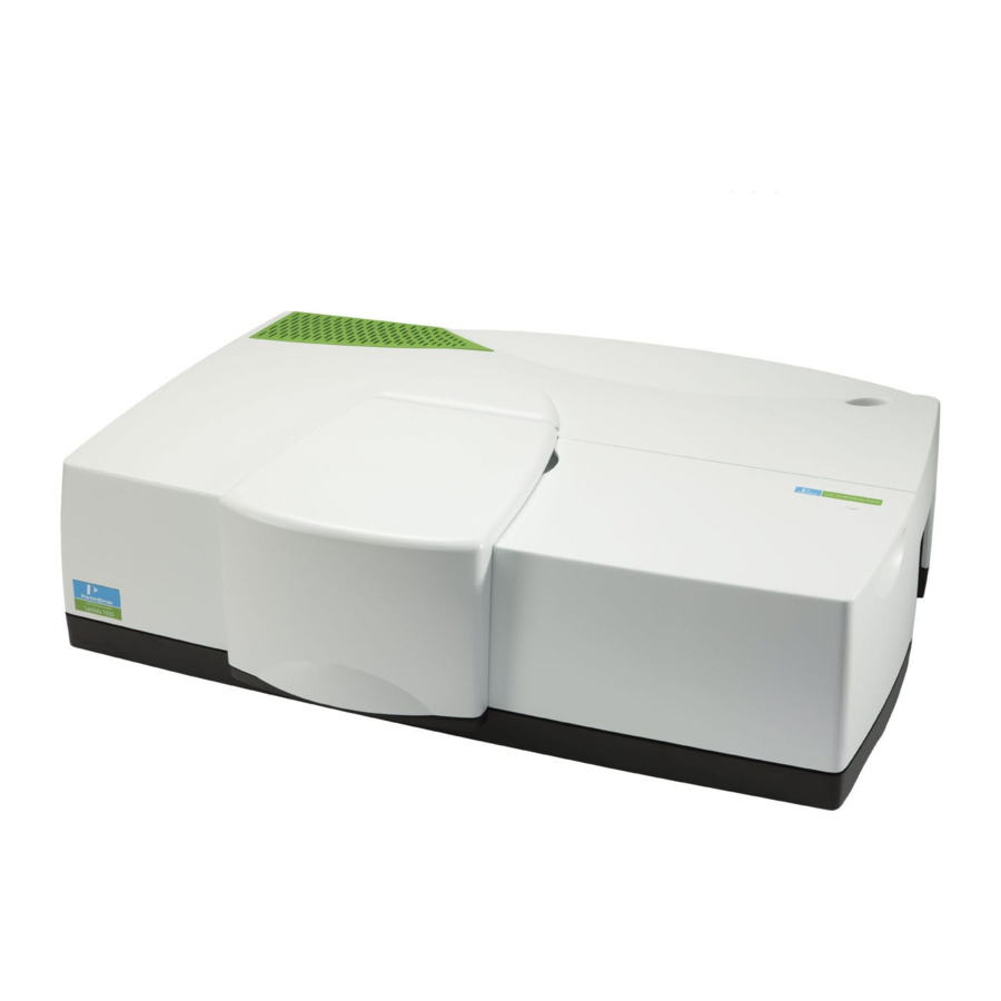
6 . High-Performance Lambda Spectrometers Hardware Guide Overview This hardware guide describes the operating procedures for the Lambda 650, 750, 850, 950 and 1050 spectrometers, plus those maintenance routines that do not necessarily require a PerkinElmer Service Engineer. Figure 1 High-performance Lambda spectrometer... - Page 7 Appendix 1 covers Waste Electrical and Electronic Equipment (WEEE) instructions for the disposal of PerkinElmer Products. Appendix 2 describes the procedure that should be followed for the decontamination and cleaning of PerkinElmer Products prior to returning them for maintenance or repair.
-
Page 8: Conventions Used In This Manual
'+' is used to show that you have to press two keys at the same time, for example, ALT+F. All eight digit numbers are PerkinElmer part numbers unless stated otherwise. Unless stated otherwise, “high-performance Lambda spectrometer” refers to the Lambda 650, 750, 850, 950, 1050 WB or 1050 NB spectrometer, as applicable. - Page 9 Introduction . 9 We use the term CAUTION to inform you about situations that could CAUTION result in serious damage to the instrument or other equipment. Details about these circumstances are in a box like this one. Caution (Achtung) Bedeutet, daß die genannte Anleitung genau befolgt werden muß, um einen Geräteschaden zu vermeiden.
- Page 10 10 . High-Performance Lambda Spectrometers Hardware Guide We use the term WARNING to inform you about situations that could result in personal injury to yourself or other persons. Details about these circumstances are in a box like this one. WARNING Warning (Warnung) Bedeutet, daß...
-
Page 11: Safety Practices
Safety Practices... -
Page 12: Overview
This advice is intended to supplement, not supersede, the normal safety codes in the user's country. It is also a supplement to the PerkinElmer standard Safety and Health Policy. The information provided does not cover every safety procedure that should be practiced. -
Page 13: Precautions
• Do not operate the instrument with any covers or parts removed. Servicing should only be carried out by a PerkinElmer Service Engineer or a similarly • authorized and trained person. Disconnect the instrument from all voltage sources before opening it for any •... -
Page 14: General Operating Conditions
14 . High-Performance Lambda Spectrometers Hardware Guide General Operating Conditions Only use your high-performance Lambda spectrometer indoors and under the following conditions: Temperature 15 °C to 35 °C Relative Humidity 80% maximum (non-condensing) If possible, avoid any adjustment, maintenance or repair of the opened, operating instrument. -
Page 15: Environmental Conditions
Safety Practices . 15 Environmental Conditions The instrument has been designed to be safe under the following conditions: Indoor use; • • Altitude up to 2000 m; • Ambient temperatures of 5 °C to 40 °C; • A maximum ambient relative humidity of 80% for temperatures up to 31 °C, decreasing linearly to 50% relative humidity at 40 °C;... - Page 16 16 . High-Performance Lambda Spectrometers Hardware Guide Waste Disposal Waste containers may contain corrosive or organic solutions and small amounts of the substances that were analyzed. If these materials are toxic, you may have to treat the collected effluent as hazardous waste. Refer to your local safety regulations for proper disposal procedures.
-
Page 17: Electrical Safety
Electrical Safety The high-performance Lambda spectrometer has been designed and tested in accordance with PerkinElmer specifications and in accordance with the safety requirements of the International Electrotechnical Commission (IEC). The high-performance Lambda spectrometer conforms to IEC 61010-1 (Safety Requirements for electrical equipment for measurement, control and laboratory use) as it applies to IEC Class 1 (earthed) appliances and therefore meets the requirements of the low-voltage EC directive 2006/95/EC. -
Page 18: Electrical Safety Issues
To ensure satisfactory and safe operation of the instrument, it is essential that the green/yellow lead of the line power cord is connected to true electrical earth (ground). If any part of the instrument is not installed by a PerkinElmer Service Engineer, make sure that the line power plug is wired correctly. -
Page 19: Emc Compliance
Safety Practices . 19 EMC Compliance EMC directive This product has been designed and tested to meet the requirements of the EMC directive 2004/108/EC. FCC rules and regulations This product is classified as a digital device used exclusively as industrial, commercial, or medical test equipment. -
Page 20: Warning Labels
20 . High-Performance Lambda Spectrometers Hardware Guide Warning Labels When this label is attached to an instrument it means refer to the manual. WARNING The following electrical warnings are shown on the rear of the instrument, as identified in Figure 2: Warning symbols shown on the spectrometer housing Figure 2 Warning labels on the high-performance Lambda spectrometer... - Page 21 Safety Practices . 21 The following warnings are shown on the inside of the lamp compartment, as identified in Figure 3: Lamp compartment Figure 3 Position of the lamp compartment...
-
Page 22: Fuses
22 . High-Performance Lambda Spectrometers Hardware Guide Fuses Electrical Hazard To prevent potential injury to yourself and damage to the instrument, switch OFF all instruments in the system and disconnect them from the WARNING line power supply before you alter, or make any new, electrical connections. - Page 23 You can hear a click as each lug snaps into place. NOTE: If you use the correct fuses but the instrument still does not work correctly, or the fuses blow repeatedly, contact your PerkinElmer Service Engineer.
-
Page 24: Moving The Instrument
CAUTION PerkinElmer Service Representative for guidance or advice. If you are only moving the instrument within the laboratory or to a nearby laboratory, then four people should lift the instrument using the handholds, as shown in Figure 6. -
Page 25: System Description
System Description... -
Page 26: Overview
26 . High-Performance Lambda Spectrometers Hardware Guide Overview The Lambda 650, 750, 850, 950 and 1050 spectrometers are versatile instruments operating in the ultraviolet and visible (UV/Vis) spectral ranges. Additionally, the Lambda 750, 950, and 1050 spectrometers operate in the near-infrared (NIR) region. The spectrometer features a double-beam, double-monochromator, ratio-recording optical system. -
Page 27: Optical System
The optical components are coated with silica for durability. Holographic gratings are used in each monochromator for the UV/Vis range and the NIR range. Lambda 650/750/850/950 Spectrometer The optical system of the Lambda 650/750/850/950 spectrometer is shown in Figure 8. Monochromator I UV/Vis... - Page 28 UV/Vis grating or the NIR grating. NOTE: The NIR grating is not available in the Lambda 650 or 850 spectrometers. The radiation is dispersed at the grating to produce a spectrum. The rotational position of the grating effectively selects a segment of the spectrum, reflecting this segment to mirror M5 and then through the exit slit.
-
Page 29: Lambda 1050 Spectrometer
NIR range. Detector change is automatic during monochromator slewing. NOTE: The PbS detector is not available in the Lambda 650 or 850 spectrometers. At the cell plane, each radiation beam is approximately 12 mm high. The width of the radiation beams is dependent on the slit width. - Page 30 30 . High-Performance Lambda Spectrometers Hardware Guide Figure 9 Optical system in the Lambda 1050 spectrometer lamp compartment Second, the automatic internal sample beam and reference beam attenuators have the following possible values: 0%, 0.1%, 1% and 100%. Third, the detector compartment has the Three Detector Module fitted as standard. A photomultiplier tube (PMT) detector is used in the UV/Vis range (175–860 nm).
-
Page 31: Sphere-Only Systems
Figure 11 The arrangement of the detectors of the Three Detector Module Sphere-only Systems In addition to the standard configurations described above, the Lambda 650/750/950/1050 spectrometers can be supplied with an integrating sphere only, containing a PMT detector for the UV-vis range and either a PbS or InGaAs detector for the NIR range. These systems have simpler optical designs than the standard configurations, and therefore the spectral scanning ranges in the UV/Vis and NIR regions are slightly reduced. - Page 32 32 . High-Performance Lambda Spectrometers Hardware Guide...
-
Page 33: Installing Your Lambda Spectrometer
Installing your Lambda Spectrometer... -
Page 34: Overview
34 . High-Performance Lambda Spectrometers Hardware Guide Overview NOTE: The first-time installation of your instrument will be carried out by a PerkinElmer Service Engineer. The following information is for reference only. Site Requirements For maximum stability and minimum maintenance, observe the following requirements when choosing where to site the instrument: •... -
Page 35: Unpacking
Take great care when installing your Lambda spectrometer, and follow the procedures described in this manual. If you require assistance, CAUTION contact your PerkinElmer Service Engineer. The instrument weighs about 77 kg. Four people are needed to lift the instrument. - Page 36 – Make sure that the compartment is free of dust or other foreign matter. NOTE: In the event of damage or missing parts, file an immediate claim with the authorized carrier, and inform your PerkinElmer office or Service Representative.
-
Page 37: Connecting To The Line Power Supply
Installing your Lambda Spectrometer . 37 Connecting to the Line Power Supply Electrical Hazard To prevent potential injury to yourself and damage to the instrument, make any electrical connections in the system before connecting to the WARNING line power supply. The spectrometer automatically adjusts to the correct operating voltage. -
Page 38: Connecting The System Components
38 . High-Performance Lambda Spectrometers Hardware Guide Connecting the System Components Electrical Hazard To prevent potential injury to yourself and damage to the instrument, switch OFF all instruments in the system and disconnect them from the WARNING line power supply before you alter any, or make any new, electrical connections. -
Page 39: Setting Up The Instrument In The Software
UV WinLab (ES) Administrator’s Guide (L6050012) provided with your software. NOTE: If your instrument is installed by a PerkinElmer Service Engineer, you should not need to do this. You will require permission to configure instruments to add a new instrument. - Page 40 40 . High-Performance Lambda Spectrometers Hardware Guide 4. Click Next. The Select Instrument Type page is displayed. 5. Select the appropriate instrument (Lambda 650 in this example) from the drop-down list and, if required, select Make this the default instrument. 6. Click Next.
- Page 41 9. Check the serial number on the right-hand side of the instrument, where the PC connects to the instrument, correct it if necessary, and then click Next. The Install Lambda 650 page is displayed. 10. Enter a Name for the instrument.
- Page 42 NOTE: If you are installing a Lambda 850, 950 or 1050 spectrometer, which has automatic attenuators, then the option Sample/Reference Beam Attenuators is also available. The Lambda 650 and 750 spectrometers have manual attenuators only. NOTE: The Common Beam Depolarizer and Sample/Reference Attenuators must be enabled on the Instrument tab of the Instrument Properties dialog.
- Page 43 Installing your Lambda Spectrometer . 43 14. Click Next. The Example Methods dialog is displayed. 15. Select the group(s) of Example Methods that you would like to install. The groups include: Color, Materials, Optics and Solar Reflectance. 16. Click Next. The Finish page displays all the selected settings.
-
Page 44: Calibrating The Instrument
2. Select the routines to be performed by the calibration. There are three calibration routines available for the Lambda 650/850 spectrometer: UV/Vis Wavelength, which calibrates the UV/Vis wavelength range, Slits, and Zero Percent T, which calibrates the electronic offsets. - Page 45 Installing your Lambda Spectrometer . 45 NIR Wavelength: – Select Manual set, Manual set 1 peak, Manual set 2 peaks, Auto search 1 peak, or Auto search 2 peaks. – Manual set enables you to enter the offset and factor (without the need to determine the values in advance).
- Page 46 The calibrations are performed in the order listed in the table. Messages below the table show the progress of the calibration. If you are performing the Zero Percent T calibration on a Lambda 650/750, you will be prompted to place the magnetic beam blocks supplied over the ports in the sample compartment wall.
-
Page 47: Installing Accessories
(PCB) fitted in the connector panel. The accessory PCB will be installed by a PerkinElmer Service Engineer. This section of the manual details changes that may need to be made to the basic spectrometer before installing an accessory, and gives an overview of the installation required for some of the specific accessories. - Page 48 48 . High-Performance Lambda Spectrometers Hardware Guide Removing the Sample Compartment Windows Each window has a magnetic frame and can be removed carefully by hand. Replace the window in its original position. Removing the Sample Compartment Baseplate 1. With the sample compartment cover open or removed, undo the four thumbscrews shown in Figure 16.
-
Page 49: Removing The Detector Unit
Installing your Lambda Spectrometer . 49 Removing the Sample Compartment 1. After removing the sample compartment cover and baseplate as described above, undo the four retaining screws shown in Figure 17. Retaining screw Locating slot Retaining screws Retaining screw Locating hole Figure 17 Four retaining screws in the sample compartment 2. - Page 50 50 . High-Performance Lambda Spectrometers Hardware Guide 3. Undo the two retaining screws located under the blanking caps on the top of the detector (Figure 18), which are accessible using the long, posidrive screwdriver supplied with the instrument. Retaining screws under blanking caps Figure 18 Undoing the retaining screws 4.
-
Page 51: Accessory Connector Panel
Installing your Lambda Spectrometer . 51 Accessory Connector Panel The accessory panel is fitted with an RS 232 interface, a USB interface, an Ethernet interface and two 15-pin connector sockets. There are also two slots for the accessory printed circuit boards (PCB) for those accessories that require them. -
Page 52: Overview Of Accessory Installation
52 . High-Performance Lambda Spectrometers Hardware Guide Overview of Accessory Installation NOTE: The spheres, Three Detector Module and the URA Accessory are covered in separate High-Performance Lambda Spectrometers User Manuals CD manuals. See the (L6050009). Automatic Cell Changers Connector on Spectrometer: 15-pin connector Installation: See the cell-changer manual... -
Page 53: Pin Configuration
Installing your Lambda Spectrometer . 53 Sipper Spectrometer connector panel Figure 22 Sipper electrical connection Pin Configuration There are two 15-pin connectors fitted to the connector panel of the high-performance Lambda spectrometer for the connection of accessories. The connectors are identically configured so that the accessories can be connected to any of them. - Page 54 54 . High-Performance Lambda Spectrometers Hardware Guide...
-
Page 55: Using The Spectrometer
Using the Spectrometer... -
Page 56: Startup Procedure
56 . High-Performance Lambda Spectrometers Hardware Guide Startup Procedure NOTE: If you have purchased any accessories, then you may want to install these first before commencing with the Startup procedure. An overview of the available accessories is on page 52. See also the specific documentation for the accessory. Do not turn power to the instrument on and off quickly as this may damage the power supply. -
Page 57: The Single-Cell Holder
Using the Spectrometer . 57 The Single-Cell Holder Description There are two single-cell holders provided with the instrument (see Figure 25): one for the sample beam and one for the reference beam. The single-cell holders are mounted on a plinth to bring them in line with the radiation beam. Locking screw for horizontal alignment... -
Page 58: Aligning The Single-Cell Holder
58 . High-Performance Lambda Spectrometers Hardware Guide To install the single-cell holder in the sample compartment: 1. Orientate the holder so that the word LAMBDA is toward the front of the sample compartment (see Figure 27). 2. Lower the holder so that the two locating holes slip onto the two studs on the two locating pins on the plinth in the sample compartment. - Page 59 Using the Spectrometer . 59 4. From the UV WinLab Explorer window, select the instrument you are using and select Manual Control from the Tools menu. 5. From the Manual Control window, select Data Collection from the Folder List and then select the Alignment Mode check box.
-
Page 60: Fine Alignment
Minimum Volume Applications To measure minimum sample volumes, use microcells (offered by PerkinElmer). The minimum sample volume required is a function of the internal width, or volume, of the cell and is specified in the following table. - Page 61 Using the Spectrometer . 61 Cell Type Cell Pathlength Minimum Part Internal Volume Number Width Required Height of 2 mm 1 cm 150 μL B0079404 liquid slightly (pair) more than height of 4 mm 1 cm 300 μL B0079402 beam (pair) Cell Pathlength...
-
Page 62: Purging The Instrument
NOTE: You cannot purge the Lambda 650 or 750 spectrometers. Oxygen absorbs radiation in the UV range below 190 nm, while water vapor absorbs radiation in the NIR range between 1350 nm and 1450 nm, 1850 nm and 1950 nm, and also between 2520 nm and 3000 nm. - Page 63 Using the Spectrometer . 63 You should keep the sample compartment closed during routine operation to prevent the water vapor and oxygen from entering. When performing operations within the sample compartment, do not leave the sample compartment cover open for any longer than is necessary.
- Page 64 64 . High-Performance Lambda Spectrometers Hardware Guide...
-
Page 65: Maintenance
Maintenance... -
Page 66: Overview
You should perform only the maintenance procedures described in this chapter. If additional maintenance is required, contact a PerkinElmer Service Engineer. Before using any cleaning or decontamination methods except those specified here, users should check with PerkinElmer that the proposed CAUTION method will not damage the equipment. -
Page 67: Daily Checks
Maintenance . 67 Daily Checks The instrument is constructed with high-quality components and requires little maintenance other than to keep it clean and free of dust. To protect the optical system from dust and fumes, you should keep the sample compartment cover closed except for when you are carrying out work in the compartment. -
Page 68: Sample Compartment Windows
68 . High-Performance Lambda Spectrometers Hardware Guide Drain holes Figure 30 Drain holes in standard sample compartment baseplate 1. First remove the cell holder or other sample-handling accessory from the sample compartment. 2. Using a soft cloth and a solution of a mild laboratory detergent, lightly scrub away all foreign matter. -
Page 69: Use And Care Of Cells
Maintenance . 69 Use and Care of Cells A good spectrometer cell is an optical device, forming a part of the optical system of the instrument with which it is used. It must be accorded the same careful treatment applied to any optical component. -
Page 70: Replacing A Lamp
70 . High-Performance Lambda Spectrometers Hardware Guide Replacing a Lamp If a lamp failure warning message is displayed, or you are seeing excessive noise on the baseline, you can replace the lamps as follows. Electrical Hazard High voltages are present at the lamp connectors in the lamp compartment –... -
Page 71: Halogen Lamp Replacement
Maintenance . 71 Halogen Lamp Replacement If the lamp burns out, or if the bulb becomes blackened after prolonged use, you should replace the lamp. Replacement lamp assemblies (B0114620) are provided complete with pre-aligned mounts. Figure 32 Pre-aligned halogen lamp (B0114620) To replace the halogen lamp: 1. - Page 72 72 . High-Performance Lambda Spectrometers Hardware Guide 4. Carefully pull the halogen lamp connector from the rear of the halogen lamp, as shown in Figure 34. Halogen lamp connector Halogen lamp assembly Halogen lamp thumbscrew Figure 34 Removing the halogen lamp connector 5.
-
Page 73: Deuterium Lamp Replacement
Maintenance . 73 Deuterium Lamp Replacement If the lamp burns out, or indicates falling energy after prolonged use, you should replace the lamp. Replacement lamp assemblies (L6022728) are provided complete with pre-aligned mounts. Figure 35 Pre-aligned deuterium lamp assembly (L6022728) To replace the deuterium lamp: 1. - Page 74 74 . High-Performance Lambda Spectrometers Hardware Guide 7. Slip the slot at the base of the lamp mount over the stud on the bracket in the lamp compartment and then secure with the thumbscrew. 8. Plug the deuterium lamp connector into the socket. NOTE: The socket in the lamp compartment is asymmetric;...
-
Page 75: Replacement Parts
Maintenance . 75 Replacement Parts Supplies, accessories, and replacement parts can be ordered directly from PerkinElmer. See the PerkinElmer website at http://www.perkinelmer.com for more information. Quantity Item Part Number Pack of 10 fuses 3.15 A time delay B0155573 Deuterium lamp, pre-aligned... - Page 76 76 . High-Performance Lambda Spectrometers Hardware Guide...
-
Page 77: Appendices
Appendices... -
Page 78: Appendix 1: Weee Instructions For Perkinelmer Products
For Customer Care telephone numbers select “Contact us” on the web page. Products from other manufacturers may also form a part of your PerkinElmer system. These other producers are directly responsible for the collection and processing of their own waste products under the terms of the WEEE Directive. -
Page 79: Appendix 2: Decontamination And Cleaning
762-4000, 8:30 a.m. - 7 p.m. EST and speak to Customer Support. In Canada, call toll free 800-561-4646 and speak to Customer Support. If you are located outside of the United States or Canada, please call your local PerkinElmer sales office for more information. -
Page 80: Index
80 . High-Performance Lambda Spectrometers Hardware Guide Index accessories lamps automatic cell changers ........52 replacement ............. 70 installation ............47 pin ..............53 sippers ............. 52 temperature sensor ......... 52 maintenance accessory panel ............ 51 cells ..............69 automatic cell changers ........52 cleaning the sample compartment .... - Page 81 Appendices . 81 UV radiation safety ..........16 temperature sensor ..........52 WEEE directive ............. 78 unpacking ............. 35...
- Page 82 82 . High-Performance Lambda Spectrometers Hardware Guide...
Need help?
Do you have a question about the Lambda 650 and is the answer not in the manual?
Questions and answers