SMC Networks JXC93 Series Manuals
Manuals and User Guides for SMC Networks JXC93 Series. We have 3 SMC Networks JXC93 Series manuals available for free PDF download: Operation Manual, Information

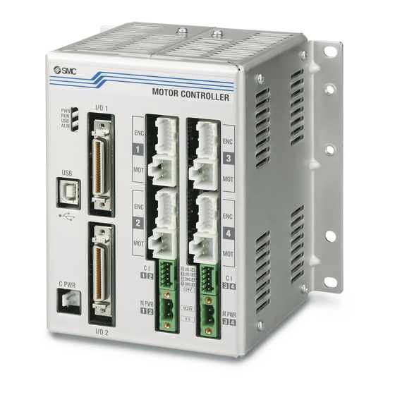
SMC Networks JXC93 Series Operation Manual (113 pages)
4-axis Step Motor Controller (EtherNet / IP type)
Brand: SMC Networks
|
Category: Controller
|
Size: 4 MB
Table of Contents
Advertisement

SMC Networks JXC93 Series Operation Manual (113 pages)
4-axis Step Motor Controller (EtherNet / IPTM type)
Brand: SMC Networks
|
Category: Controller
|
Size: 4 MB
Table of Contents
SMC Networks JXC93 Series Information (16 pages)
4 Axis Step Motor Controller
Brand: SMC Networks
|
Category: Controller
|
Size: 5 MB
Table of Contents
Advertisement