
Related Manuals for VIPA CP143plus


Summary of Contents for VIPA CP143plus
- Page 1 Manual CP143 H1 / TCP/IP H1 and TCP/IP Order-No.: VIPA SSN-HB89E Rev. 00/07 Subject to change to cater for technical progress.
- Page 2 Lerrzeichen...
- Page 3 The information contained in this manual is subject to change without notice. The contents may be changed without VIPA giving prior notice at any time. The software described in this manual is supplied on the basis of a general license. This license entitles you to make copies for use within your organization only.
- Page 4 CP143 H1 / TCP/IP manual About this manual This manual describes applications of the CP143plus and CP143 TCP/IP modules. These modules are plug-compatible with any PLC (AG-115U trough AG-188U) and do not require forced air ventilation. The standard handling modules (SEND, RECEIVE) that are supplied by Siemens may be used for TCP/IP task processing by the PLC.
-
Page 5: Table Of Contents
CP143 H1 / TCP/IP manual Contents Contents 1 INTRODUCTION ......................1-1 1.1 Safty and handling precautions for the user ............1-1 1.1.1 Handling electrostatically sensitive modules ............1-1 1.1.2 Shipping electrostatically sensitive modules.............1-2 1.1.3 Tests and modifications to electrostatic sensitive modules ......1-2 1.2 General........................1-3 1.3 Operation .......................1-4 1.4 Construction......................1-4 2 COMMUNICATION PROTOCOLS ................2-1... - Page 6 4.1.3 Sockets and plugs.................... 4-5 4.2 The CP143plus firmware..................4-10 4.2.1 Components ....................4-10 4.2.2 The structure of the CP143plus ..............4-11 4.2.3 Further information on the CP143plus ............4-12 4.3 CP143 TCP/IP firmware ..................4-14 4.3.1 Components ....................4-14 4.3.2 The structure of the CP143 TCP/IP ...............
- Page 7 CP143 H1 / TCP/IP manual Contents 5.8 Configuration of connections ................5-25 5.8.1 Structure of the configuration windows............5-25 5.8.2 The control field of the configuration window ..........5-26 5.8.3 Indirect addressing ..................5-27 5.8.4 Multi-connections....................5-29 5.8.5 List of connections..................5-31 5.8.6 Clearing all connections .................5-32 5.9 General test functions ..................5-33 5.9.1 Ident .......................5-33 5.9.2 Anzw Dump ....................5-34...
- Page 8 Contents CP143 H1 / TCP/IP manual Appendix ........................A-1 A Technical data ......................A-1 B Error messages from the NCS configuration program ........B-1 C List of abbreviations ....................C-1 D List of figures......................D-1 E List of tables ......................E-1 F Index ......................... F-1 Rev.
-
Page 9: Introduction
1 Introduction 1.1 Safty and handling precautions for the user 1.1.1 Handling electrostatically sensitive modules 1.1.2 Shipping electrostatically sensitive modules 1.1.3 Tests and modifications to electrostatic sensitive modules 1.2 General 1.3 Operation 1.4 Construction... - Page 10 Lerrzeichen...
-
Page 11: Introduction
1.1 Safty and handling precautions for the user 1.1.1 Handling electrostatically sensitive modules The modules produced by VIPA carry MOS-VLSI components. These components are highly susceptible to high voltages that may be caused by electrostatic discharges. These modules bear the following symbol to highlight the sensitive nature of the components: This symbol is attached to the module, module carriers or on the packing material and indicates that the module is sensitive to electrostatic discharge. -
Page 12: Shipping Electrostatically Sensitive Modules
Safty and handling precautions for the user CP143 H1 / TCP/IP manual 1.1.2 Shipping electrostatically sensitive modules Modules to be shipped must be packed in their original container. You may also wrap additional conductive material around modules that are about to be shipped. Conductive material comes in the form of antistatic foils or metallized enclosures. -
Page 13: General
CP143 H1 / TCP/IP manual Introduction 1.2 General You may use the VIPA CP143plus or the CP143 TCP/IP to implement Industrial Ethernet H1 or TCP/IP networks in your offices or factories. The software used to configure the modules is compatible with MS-DOS , WINDOWS 3.11,... -
Page 14: Operation
CPU of this task. This operation covers the entire ISO-OSI level model. The VIPA CP143 H1 / TCP/IP module is controlled by the standard handler modules of the installed PLC. The following modules are required for interfacing with the VIPA CP143 H1 / TCP/IP: SEND ALL, RECEIVE ALL, SYNCHRON, SEND DIREKT, RECEIVE DIREKT, FETCH. -
Page 15: Communication Protocols
2 Communication protocols 2.1 H1 protocol 2.1.1 Structure of Industrial Ethernet H1 2.1.2 Operation 2.1.3 Structure and operation of the PLC interface 2.2 TCP/IP protocol 2.2.1 ISO-OSI level model 2.2.2 TCP/IP principle of operation 2.2.3 TCP/IP services... - Page 16 Lerrzeichen...
- Page 17 H1 / TCP/IP manual CP143 Communication protocols 2 Communication protocols 2.1 H1 protocol The Industrial Ethernet H1 LAN provides the basis for the implementation of large, high-tech, decentralized automation systems. Industrial Ethernet H1 is the complete solution for the implementation of large, open networks between the different departments of a company. Compatible devices include: •...
-
Page 18: Operation
A dual-port RAM connects the CP143 H1 / TCP/IP directly to the back plane bus-LAN. At the PLC the dual-port RAM is available as a standard-CP-interface with 4 tiles. Any H1 data traffic is conducted via standard handler modules (SEND and RECEIVE). Node (station) per segment CP143plus connection cable 727-1 (max. 50m) Transceiver Repeater... -
Page 19: Tcp/Ip Protocol
H1 / TCP/IP manual CP143 Communication protocols 2.2 TCP/IP protocol The TCP/IP protocol was an integral component of the Berkeley UNIX version 4.2 and as such it became a de-facto standard in local-area networks. Many manufacturers of workstations have since opted for the ethernet - TCP/IP -UNIX combination. - Page 20 H1 / TCP/IP manual TCP/IP protocol CP143 2.2.1.1 General The ISO-OSI level model is based upon a suggestion that was developed by the International Standards Organization (ISO). It represents the first step in the direction of an international standard for the different protocols currently in use. The model is referred to as ISO-OSI level model. OSI is the abbreviation for Open Systems Interconnection, that is communication between open systems.
- Page 21 H1 / TCP/IP manual CP143 Communication protocols Level 5 Session layer The session layer provides the links that enable users of different systems to communicate. In addition to the standard transport services the session layer also provides high-level services that may be useful for certain applications.
- Page 22 H1 / TCP/IP manual TCP/IP protocol CP143 2.2.1.3 TCP/IP in relation to the ISO-OSI level model TCP/IP is older than the ISO-OSI level model. For this reason the different layers can not be applied directly to TCP/IP. The TCP/IP network layers correspond to level 1 and 2 of the ISO-OSI model. Levels 5 and 6 of the ISO-OSI model are already integrated into the protocols of the TCP/IP application layer.
-
Page 23: Tcp/Ip Principle Of Operation
H1 / TCP/IP manual CP143 Communication protocols 2.2.2 TCP/IP principle of operation TCP and IP are only two of the many protocols required for the establishment of a complete network architecture. The application layer of the computer supplies programs like FTP and Telnet. The standard handler modules of the program define the application layer of the CP143 TCP/IP. - Page 24 H1 / TCP/IP manual TCP/IP protocol CP143 Rev. 00/07...
-
Page 25: Network Planning
3 Network planning 3.1 Ethernet network-terminology 3.2 Thin-ethernet-cable networks 3.2.1 Thin-ethernet-cable network-layout 3.2.2 Regulations and specifications 3.2.3 Technical data thin-ethernet 3.3 Thick-ethernet-cable networks 3.3.1 Thick-ethernet-cable network-layout 3-10 3.3.2 Regulations and specifications 3-11 3.3.3 Technical data thick-ethernet 3-13 3.4 Combining thin/thick ethernet cable in networks 3-14 3.4.1 Combination of thin/thick ethernet cable hardware 3-14... - Page 26 LerrzeicLerrzeichenhen...
-
Page 27: Fig. 3-1: Parts Of An Ethernet Network
CP143 H1 / TCP/IP manual Network planning 3 Network planning 3.1 Ethernet network-terminology An ethernet network provides a communication link between different stations on the network. The stations on the network may consist of personal computers, industrial computers, automation equipment etc. Stations are connected to the network and located a certain minimum distance from each other. - Page 28 Ethernet network-terminology CP143 H1 / TCP/IP manual Three types of ethernet cable exist: • Thin-ethernet-cable (also called thin ethernet cable or Cheapernet-cable). • Thick-ethernet-cable (also called thick ethernet cable or standard ethernet-cable or yellow-cable). • Twisted pair-cable (telephone cable) Thin ethernet-cable is far more economical than thick ethernet-cable. This applies to the cost of the cable, the cost of installation and any additional hardware.
-
Page 29: Thin-Ethernet-Cable Networks
BNC-connectors are used to interconnect two thin-ethernet network cables. Where two portions of a thin-ethernet network must be linked these connectors have a distinct advantage over T-pieces. You may obtain these BNC-connectors from VIPA GmbH. BNC-T-pieces The two sockets located at opposite ends of the T-piece provide the connection to the BNC-connectors on the thin-ethernet cable. -
Page 30: Fig. 3-2: Thin Ethernet Network Hardware
Thin-ethernet-cable networks CP143 H1 / TCP/IP manual CP 143 H1 / TCP/IP Fig. 3-2: Thin ethernet network hardware Rev. 00/07... -
Page 31: Thin-Ethernet-Cable Network-Layout
CP143 H1 / TCP/IP manual Network planning 3.2.1 Thin-ethernet-cable network-layout Here follows a summary of the restrictions and the rules that apply to a thin-ethernet-cable network. Fig. 3-3 is an illustration of this summary. Restrictions • Maximum number of network segments: (3 coaxial segments with network stations and 2 interconnecting segments without network stations) -
Page 32: Regulations And Specifications
Thin-ethernet-cable networks CP143 H1 / TCP/IP manual 3.2.2 Regulations and specifications Certain basic regulations must be observed when planning or installing a network: • The cabling of a network consists of a number of segments. Each segment must be terminated with its characteristic impedance (terminator) of 50 Ω. -
Page 33: Technical Data Thin-Ethernet
CP143 H1 / TCP/IP manual Network planning Guidelines for the routing and installation of network components • As a rule, a minimum distance of 1m is prescribed with respect to electrical equipment, cabling and other components that could produce electromagnetic and electrostatic fields. This includes parallel runs of power or high-tension cables, circuit breakers etc. -
Page 34: Thick-Ethernet-Cable Networks
Thick-ethernet-cable networks CP143 H1 / TCP/IP manual 3.3 Thick-ethernet-cable networks Thick-ethernet-cable network hardware This chapter contains a description and an illustration (Fig. 3-4) of the hardware required for a thick-ethernet-network. Network adapter Network adapters are installed in every station on the network and linked by means of a network cable to provide the communication medium between these stations. -
Page 35: Fig. 3-4: Thick-Ethernet Network Hardware
CP143 H1 / TCP/IP manual Network planning CP 143 H1 / TCP/IP Fig. 3-4: thick-ethernet network hardware Rev. 00/07... -
Page 36: Thick-Ethernet-Cable Network-Layout
Thick-ethernet-cable networks CP143 H1 / TCP/IP manual 3.3.1 Thick-ethernet-cable network-layout Here follows a summary of the restrictions and the rules that apply to a thick-ethernet-cable network. Fig. 3-5 is an illustration of this summary. Restrictions • Maximum number of network segments: (3 coaxial segments with network stations and 2 interconnecting segments without network stations) -
Page 37: Regulations And Specifications
CP143 H1 / TCP/IP manual Network planning 3.3.2 Regulations and specifications Certain basic regulations must be observed when planning or installing a network: • The cabling of a network consists of a number of segments. Both ends of each segment must be terminated with its characteristic impedance (terminator) of 50 Ω. - Page 38 Thick-ethernet-cable networks CP143 H1 / TCP/IP manual Guidelines for the routing and installation of network components: • As a rule, a minimum distance of 1m is prescribed with respect to electrical equipment, cabling and other components that could produce electromagnetic and electrostatic fields. This includes parallel runs of power or high-tension cables, circuit breakers etc.
-
Page 39: Technical Data Thick-Ethernet
CP143 H1 / TCP/IP manual Network planning 3.3.3 Technical data thick-ethernet Coaxial cable 50 Ω ± 2 Ω Impedance ± 3 Ω with a period > 2 m Impedance linearity Inductivity 0,21 µH/km 85 pF ± 5 pF Capacity ≤ 18 dB/km for a 10 MHz sine wave Attenuation ≤... -
Page 40: Combining Thin/Thick Ethernet Cable In Networks
Combining thin/thick ethernet cable in networks CP143 H1 / TCP/IP manual 3.4 Combining thin/thick ethernet cable in networks It is possible to combine thin-ethernet and thick-ethernet cabling in a single network.. The lower price of the thin-ethernet cable may provide a more cost-effective solution than a system that is purely based on thick-ethernet cable. -
Page 41: Thin/Thick Ethernet Cable Combination Network-Layout
CP143 H1 / TCP/IP manual Network planning 3.4.2 Thin/thick ethernet cable combination network-layout This chapter describes a method of combining thin ethernet cable and thick ethernet cable in a single network segment. This method employs as much thin ethernet cable as possible. Fig 2-7 illustrates this technique of combining thin and thick ethernet cable. -
Page 42: Twisted Pair
Twisted Pair CP143 H1 / TCP/IP manual 3.5 Twisted Pair Twisted Pair network hardware A twisted pair-network can only have a star-type configuration. This topology requires a hub that supports the star-type configuration. The following paragraphs contain a description of the hardware required for implementing a twisted pair network. -
Page 43: Fig. 3-9: Twisted Pair Network Hardware
CP143 H1 / TCP/IP manual Network planning Twisted pair plug Twisted pair cable Star coupler (Hub) Power supply Tx Rx Tx Rx Tx Rx Tx Rx Tx Rx Tx Rx Fig. 3-9: Twisted pair network hardware Rev. 00/07 3-17... -
Page 44: Planning A Network-Layout
Planning a network-layout CP143 H1 / TCP/IP manual 3.6 Planning a network-layout At this point you are aware of the limitations of the different cabling systems, and you can provide answers to the following questions with respect to the network that you have to implement: Determination of network requirements •... -
Page 45: Standards And Specifications
LAN and other basic principles that are important for communicating on the network. The VIPA H1-network was developed to satisfy the ISO standards and specifications. The standards and specifications for networking systems were determined by international and national committees. - Page 46 Standards and specifications CP143 H1 / TCP/IP manual 3-20 Rev. 00/07...
-
Page 47: The Cp143 H1 / Tcp/Ip Network Board
4.1.1 Components of the module 4.1.2 Jumper settings 4.1.3 Sockets and plugs 4.2 The CP143plus firmware 4-10 4.2.1 Components 4-10 4.2.2 The structure of the CP143plus 4-11 4.2.3 Further information on the CP143plus 4-12 4.3 CP143 TCP/IP firmware 4-14 4.3.1 Components 4-14 4.3.2 The structure of the CP143 TCP/IP... - Page 48 Lerrzeichen...
-
Page 49: Fig. 4-1: Construction Of The Cp143 H1 / Tcp/Ip
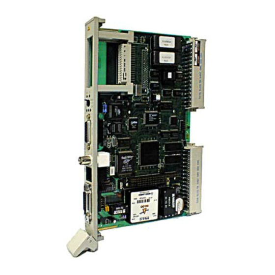
H1 / TCP/IP manual CP143 The CP143 H1 / TCP/IP network board 4 The CP143 H1 / TCP/IP network board 4.1 The construction of the module Fig. 4-1: Construction of the CP143 H1 / TCP/IP Rev. 00/07... - Page 50 H1 / TCP/IP manual The construction of the module CP143 4.1.1 Components of the module • 80486 SLC 33 MHz CPU • 1MB main memory • PG interface which is compatible with the Siemens CP1430 • EPROM socket • 4KB dual-port RAM as CP interface •...
-
Page 51: Jumper Settings
H1 / TCP/IP manual CP143 The CP143 H1 / TCP/IP network board 4.1.2 Jumper settings Fig. 4-2: Location of jumpers Jumpers X11 to X15 must either all face left or face right! Any other combination could cause permanent damages to the module! The configuration of this module is determined by means of jumpers. - Page 52 H1 / TCP/IP manual The construction of the module CP143 4.1.2.1 AUI / TP (X11-X15) changeover This jumper determines the pin-allocation of the 15-pin socket. You may choose between twisted pair (TP) and AUI. Jumpers X11 to X15 must always be in the same position. linked The 15-pin socket is set for AUI.
-
Page 53: Sockets And Plugs
H1 / TCP/IP manual CP143 The CP143 H1 / TCP/IP network board 4.1.3 Sockets and plugs 4.1.3.1 The position of sockets and plugs Fig. 4-3: Front view CP143 H1 / TCP/IP Rev. 00/07... -
Page 54: Tab. 4-1: Pin Configuration Of The 15-Pole Aui-/Tp Socket
H1 / TCP/IP manual The construction of the module CP143 4.1.3.2 Pin-configuration for sockets and plugs The figures show the respective sockets when the module is viewed from the frame. The top of the figure is equivalent to the top of the frame. 4.1.3.2.1 Pin-assignment for the AUI-/TP socket (15-pole) The 15-pole D-type socket connects to a transceiver via a drop-cable. -
Page 55: Tab. 4-2: Pin Configuration Of The Pg Interface
H1 / TCP/IP manual CP143 The CP143 H1 / TCP/IP network board 4.1.3.2.2 Pin configuration for the D-type socket with PG interface (15-pole) The 15-pole D-type socket with the screw-type locks is intended for the connection of a programmer. The following table shows the pin-configuration for the socket: Signal MEXT (external ground, screen) TTY IN - (current output) - Page 56 H1 / TCP/IP manual The construction of the module CP143 4.1.3.2.4 Base connector (48-pole knife-edge connector) Base connector X1 UBAT PESP ADB12 ADB00 /CPKL ADB13 ADB01 /MEMR ADB14 ADB02 /MEMW ADB15 ADB03 /RDY ADB04 ADB05 ADB06 ADB07 ADB08 ADB09 ADB10 ADB11 +24V BASP...
- Page 57 H1 / TCP/IP manual CP143 The CP143 H1 / TCP/IP network board 4.1.3.2.5 EPROM socket -CS3 -CS1 -CS4 -CS2 UBAT Rev. 00/07...
-
Page 58: The Cp143Plus Firmware
The CP143plus firmware CP143 4.2 The CP143plus firmware Fig. 4-4 shows the structure of the CP143plus firmware. This figure contains those components that interact to determine the characteristics of the CP. 4.2.1 Components The individual components communicate via the operating system functions of a real-time kernel (RTK). -
Page 59: The Structure Of The Cp143Plus
Libraries containing access functions for the TP4-protocol stack TP4(H1) protocol stack Operating system operating system divided into three independent units. A real-time kernel defines the interface for tasks and hand- lers Fig. 4-4: The structure of the CP143plus Rev. 00/07 4-11... -
Page 60: Further Information On The Cp143Plus
• The run-up time of the CP143plus is app. 10 seconds. For this reason the requirements of balanced synchronization characteristics (an HTB synchronization module waits between 8 and 10 seconds, depending on the type of CPU) can not be met. -
Page 61: Tab. 4-4: Block Size
H1 / TCP/IP manual CP143 The CP143 H1 / TCP/IP network board 4.2.3.2 Generation of a multicast address from the ethernet address The TP4 protocol stack generates a MC address from the ethernet address. This function is required as the ethernet controller (hardware) uses the MC address for message filters. 4.2.3.3 Broadcast The broadcast address is always FFFFFFFFFFFFh. -
Page 62: Cp143 Tcp/Ip Firmware
H1 / TCP/IP manual CP143 TCP/IP firmware CP143 4.3 CP143 TCP/IP firmware Fig. 4-5 shows the structure of the CP143 TCP/IP firmware. This figure contains those components that interact to provide the functionality of the CP. 4.3.1 Components The individual components communicate via the operating system functions of a real-time kernel (RTK). -
Page 63: The Structure Of The Cp143 Tcp/Ip
H1 / TCP/IP manual CP143 The CP143 H1 / TCP/IP network board 4.3.2 The structure of the CP143 TCP/IP Dual-port-RAM (DPR) PLC-Interrupt PG-Interrupt Interrupt handler and task Interrupt handler and task TCP-IP Application Tools • List processing The application consists of n tasks. -
Page 64: Further Information On The Cp143 Tcp/Ip
H1 / TCP/IP manual CP143 TCP/IP firmware CP143 4.3.3 Further information on the CP143 TCP/IP 4.3.3.1 System properties The system properties of a CP must not be regarded as limitations or as design faults. Instead, certain functions may not be accessible or they are purposely removed for the security of the overall system. -
Page 65: Fig. 4-6: Conversion Of Ethernet Address Into An Ip Address
H1 / TCP/IP manual CP143 The CP143 H1 / TCP/IP network board 4.3.3.2 The relationship between the ethernet ADR for H1 and the IP-ADR for TCP/IP The CP 143 TCP/IP has a default ethernet address after it was turned on for the first time or after it has been reset. -
Page 66: Organization Format (Org Format)
H1 / TCP/IP manual CP143 TCP/IP firmware CP143 4.3.4 Organization format (ORG format) The organization format is another name for an addressing structure that describes the data areas of the PLC. For READ and WRITE the ORG block is optional. The ORG identifier defines the memory area that must be addressed. -
Page 67: Tab. 4-8: Org-Formats For Plcs (Org-Identifier 05H-08H)
H1 / TCP/IP manual CP143 The CP143 H1 / TCP/IP network board PLC area ORG-identifier Description Source/destination data Source/destination data Source/destination data Source/destination data from/into peripheral from/into counter cells from/into timer cells from/into system data module. Input modules area (BS and BS') for source data, output modules for destination data... -
Page 68: Structure Of The Plc-Header
H1 / TCP/IP manual CP143 TCP/IP firmware CP143 4.3.5 Structure of the PLC-header The following messages lists the valid ORG identifiers. The entered "length" must never be -1 (FFFFh). 4.3.5.1 FETCH/WRITE for WRITE Request message Acknowledgement message System identifier ="S" System identifier ="S"... - Page 69 H1 / TCP/IP manual CP143 The CP143 H1 / TCP/IP network board 4.3.5.2 SEND / RECEIVE with TRADA (Transparent data exchange) TRADA stands for transparent data exchange. Transparent data exchange allows to transmit data of varied length. A 16-byte header which indicates the length is preceding the user data which have to be transmitted.
-
Page 70: Status- And Error Indicators
H1 / TCP/IP manual CP143 TCP/IP firmware CP143 4.3.6 Status- and error indicators Status and error indicators are provided by the handler modules • via the ANZW indicator word (information for task processing) • via the configuration error byte PAFE (indicator for an incorrect configuration for a task) 4.3.6.1 Contents and structure of the indicator word ANZW The indicator word has the following structure: Fig. - Page 71 H1 / TCP/IP manual CP143 The CP143 H1 / TCP/IP network board • Status management byte 1, bit 0 to bit 3 These indicate whether a task has already been started, whether an error has occurred or whether the task has been inhibited, e.g. if a virtual connection does not exist. Bit 0: Handshake possible Set: by the interface according to the "Reset"-indicator in the task status bit.
- Page 72 H1 / TCP/IP manual CP143 TCP/IP firmware CP143 • Data management byte 1, bit 4 to bit 7 This area indicates whether a data transfer is still active or whether data transmission or reception has been completed. The "Enable / Disable" bit can be used to inhibit the transfer of data for the respective task.
- Page 73 H1 / TCP/IP manual CP143 The CP143 H1 / TCP/IP network board Bit 7: Disable / enable blocking of data Set: by the user: to prevent overwriting of a block of data by the RECEIVE- module or to stop transmission of a data block by the SEND-module (only for the first data block).
- Page 74 H1 / TCP/IP manual CP143 TCP/IP firmware CP143 Remote error An error occurred at the remote station during a READ/WRITE task. Connection error The connection for a task has not been established. This error will disappear as soon as a connection can be established.
- Page 75 H1 / TCP/IP manual CP143 The CP143 H1 / TCP/IP network board 4.3.6.2 Important status and error indicators of the CP143 H1 / TCP/IP Here follow important status and error indicators that may be signalled via the “indicator word”. The data consists of "HEX"-patterns that are similar to those of the status / control-var-test function of the PG on the PLC.
-
Page 76: Tab. 4-10:Indicator Word Conditions For Send
H1 / TCP/IP manual CP143 TCP/IP firmware CP143 The following tables show the most important indicator word combinations: Indicators for SEND H1 condition Prio 0/1 Prio 2 Prio 3/4 TCP/IP condition Prio 1 Prio 2 Prio 3 after a restart 0 A 0 A 0 A 0 A 0 0 0 8... -
Page 77: Tab. 4-13:Indicator Word For Send With An Htb-Identifier "Nn
H1 / TCP/IP manual CP143 The CP143 H1 / TCP/IP network board Here follow the indicators for SEND or RECEIVE when the handler module identifier is "NN" (no source / destination parameters) H1 condition Prio 0/1 Prio 2 Prio 3/4 TCP/IP condition Prio 1 Prio 2... -
Page 78: Fig. 4-8: Parameter Error Byte Pafe
H1 / TCP/IP manual CP143 TCP/IP firmware CP143 4.3.6.3 Parameter configuration error byte PAFE The PAFE is set when the handler module detects a parameter error. Fig. 4-8: Parameter error byte PAFE Error number: no error incorrect ORG-format area does not exist area too small QVZ-error incorrect indicator word... -
Page 79: Software
5 Software 5.1 General 5.2 Installing and starting the program 5.3 Overview of available functions 5.4 Using on-line help 5.5 The base file 5.5.1 Loading, saving and deleting the base file 5.5.2 Printing the base file 5.5.3 Transferring the base file 5.6 Initialization 5-13 5.6.1 CP init... - Page 80 Lerrzeichen...
- Page 81 You may use the following configuration options: • Off-line You configure the connection and transfer the base file into an EPROM. You may use the VIPA EPROM programmer (Order-No.: VIPA MC5-KS85) or a PG7xx to program the EPROM. • On-line...
- Page 82 H1 / TCP/IP manual Installing and starting the program CP143 5.2 Installing and starting the program The following files are located on the disk supplied with the package: This is the executable configuration program. NCS.EXE Except for the help text, this file contains all the documentation of NCS.TXT the configuration program.
-
Page 83: Fig. 5-1: The Menu Structure Of The Parameter Configuration Program
You may close all connections by means of a single menu command. See chapter 5.8 Transfer You may use the VIPA-EPROM programmer or the PG7xx-EPROM programmer to transfer your data into an EPROM. It is also possible to configure the CP in on-line mode directly via the network or via the serial interface (remote configuration). - Page 84 H1 / TCP/IP manual Overview of available functions CP143 Test This menu item contains functions for displaying data from a specific target module. You must specify the target module in Init/Online. Ident returns the address and the serial number of the target module. Anzw Dump displays all indicator words from 0 through 223 in hexadecimal form.
-
Page 85: Using On-Line Help
H1 / TCP/IP manual CP143 Software 5.4 Using on-line help Whenever you require help you may press the <F1> key . You will also find help buttons at many points throughout the program. You may use the left mouse button to click on these buttons or you may access them by means of the <Tab>-key (tabulator) and the Enter-key. -
Page 86: The Base File
H1 / TCP/IP manual The base file CP143 5.5 The base file The base file, which is also called the data base file or connection parameter file, contains all the parameters that may be configured by means of the NCS configuration software. A saved base file may be transferred into an EPROM or directly to the CP. -
Page 87: Printing The Base File
This text file has the name of the base file with an extension prn. It is created in the current directory. You can use a text processor to open this file and to edit its contents. Here follows an example of the base file in text form: VIPA NCS-Projektierung Initialisierungsparameter Datum : 06.07.97... -
Page 88: Transferring The Base File
The NCS provides two options to transfer the base file into the CP: • by means of an EPROM that you have created using the VIPA-EPROM programmer or the • Via the serial interface or the network in remote mode. - Page 89 H1 / TCP/IP manual CP143 Software 5.5.3.2 Data base ↔ ↔ PG-EPROM ↔ ↔ You can only use the EPROM functions in conjunction with a PG7xx and the respective EPROM drivers. Otherwise you will receive an error message! The diskette included in the package contains a program RUNNCS.BAT. This program loads the EPROM driver as a memory resident TSR and starts the configuration program NCS.EXE.
- Page 90 H1 / TCP/IP manual The base file CP143 Data base ↔ ↔ EPROM ↔ ↔ When you select Data base ↔ EPROM from Transfer the interactive window "Data base<>EPROM" will be displayed. If the program responds with an error message "Eprom-driver not installed!" the driver could not be installed.
-
Page 91: Fig. 5-4: Window For Remote Configuration
H1 / TCP/IP manual CP143 Software 5.5.3.3 Data base ↔ ↔ CP ↔ ↔ The remote functions provide the different functions required for remotely controlling the CP module (start, stop and delete), to request the status from the CP and to transfer data base files into the CP. - Page 92 H1 / TCP/IP manual The base file CP143 Transferring the base file The following points must be noted when base data is transferred between a CP and a PC: • Communication parameters must have been set in Online. • A transfer is only possible when the PLC is stopped (STOP status). Please ensure that your PLC has been STOPped.
-
Page 93: Initialization
H1 / TCP/IP manual CP143 Software 5.6 Initialization Every now configuration requires initialization. It is necessary to initialize the identification parameters as well as H1 and TCP/IP-parameters of the CP143 H1 / TCP/IP-module. The initialization is not required if you have already loaded a base file. You can find the initialization functions under menu item Init. - Page 94 H1 / TCP/IP manual Initialization CP143 Frame base address The frame base address Frame base address determines the origin of the frames that are inserted into the memory area of the controller. The PLC program normally operates on the base frame. Any other frames may be used by other controller or systems. The frame base address must be divisible by 4 and it is located between 0 and 255.
-
Page 95: Online
H1 / TCP/IP manual CP143 Software 5.6.2 Online Online parameters must be specifies when functions are to be used that access the module directly via the network or via the serial interface. Online functions are only available from firmware level V110 and an NCS V2.1. -
Page 96: System Configuration
H1 / TCP/IP manual Initialization CP143 5.6.3 System configuration When you select system configuration a dialog window containing the general settings for optimizing the system performance is displayed. Fig. 5-7: System configuration parameters SNMP active When this item is selected the Simple Network Management Protocol will be used. SNMP is normally used for UDP connections. -
Page 97: Real-Time Clock Functions
H1 / TCP/IP manual CP143 Software 5.7 Real-time clock functions 5.7.1 General Many practical situations require that the operations are synchronized and referenced to real time. The real-time clock functions of the CP143 module may be used to synchronize up to 256 modules with an accuracy of 10ms. -
Page 98: Construction Of A Synchronized System
H1 / TCP/IP manual Real-time clock functions CP143 5.7.3 Construction of a synchronized system: Fig. 5-9: Construction of a synchronized system The DCF-77 module receives highly accurate time information and transfers this to the PLC. The PLC generates a timing message that is transferred via the LAN. This message synchronizes all CP143 modules connected to the H1-network. -
Page 99: Master Clock Initialization
Every CP may assume the role of master provided that it has been configured as a master. You may mix and match VIPA CPs and Siemens CPs. Please ensure that you use the MMS-timing format as Siemens supports only this format. - Page 100 Byte 7 Flag e: 0=time from DCF; 1=from dynamic master BCD-Format The BCD format is a plain and readable alternative. If you are only employing VIPA CP143 modules the CPs can be configured to accept BCD formatted messages. 1/10s 1/100s...
-
Page 101: Important Considerations When Using Real-Time Clock Functions
• use consistent cycle times for SYNC messages • use a consistent format for time • the format for time must be MMS when you are employing CPs from VIPA as well as Siemens. • byte 6 of the ethernet address of every CP must be different, otherwise it could happen that two CPs would attempt to become master simultaneously and therefore block the System. - Page 102 H1 / TCP/IP manual Real-time clock functions CP143 Clock status, status message in the indicator word Setting the clock Hex Description completed without errors protocol error, bad time No errors when reading clock Hex Description Explanation clock master CP is master clock and is currently active clock slave synchronous CP is slave clock (the time transmitter is active) clock slave invalid...
-
Page 103: Test Functions For The Clock
H1 / TCP/IP manual CP143 Software 5.7.8 Test functions for the clock The test functions for the clock are for use in online mode. You must specify parameters for online transfers using the Online function located under Init (see chapter 5.6.2). The test functions for the clock are available via the menu item Test. - Page 104 H1 / TCP/IP manual Real-time clock functions CP143 current time The current time. You can modify this value and it is transferred to the CP when you select "set". time difference You may enter the time difference in steps of 0,5 hours. This option is useful for daylight saving applications (summer and winter time).
-
Page 105: Configuration Of Connections
H1 / TCP/IP manual CP143 Software 5.8 Configuration of connections New configurations require that an initialization is performed. (see chapter 5.6). The initialization determines the station that must be configured. The CP143 H1 / TCP/IP module is compatible with four types of communication connection: •... -
Page 106: The Control Field Of The Configuration Window
H1 / TCP/IP manual Configuration of connections CP143 5.8.2 The control field of the configuration window Fig. 5-13: Control field of a parameter configuration window [ OK ] After confirmation the new connection is accepted. You may also press the Enter key instead of [OK]. -
Page 107: Indirect Addressing
H1 / TCP/IP manual CP143 Software 5.8.3 Indirect addressing The configuration windows for H1-transport or TCP-connections allow access to the input window for indirect addressing via the < IndAdr > button. Indirect addressing can only be used with the job types FETCH and WRITE. -
Page 108: Tab. 5-2: Data Word For The Indicator Word For Indirect Addressing
H1 / TCP/IP manual Configuration of connections CP143 Indicator word Specifies a data word on the PLC that contains the specifications for FETCH and WRITE Operand DB-No. Address Type 1..255 0..2040 Data module 1..255 0..2040 extended data module 0..252 Flag word Tab. -
Page 109: Multi-Connections
H1 / TCP/IP manual CP143 Software 5.8.4 Multi-connections Except for the configuration window for H1-datagram connections, all configuration windows provide the facility to configure multi-connections. Multi-connections refer to multi-drop connections. Here you may configure a second SSNR/ANR for an existing SSNR/ANR and its TSAP or port. - Page 110 H1 / TCP/IP manual Configuration of connections CP143 Job number (ANR) A job number{ XE "Job number" } must be allocated to each connection that should be used by Siemens handler modules. This number is used to access the connection from the PLC program.
-
Page 111: List Of Connections
H1 / TCP/IP manual CP143 Software 5.8.5 List of connections You may obtain a list of the configured connections for the respective protocol from the configuration window. This means that the content of the connection list is dependent on the interactive window from where the list was requested. -
Page 112: Clearing All Connections
H1 / TCP/IP manual Configuration of connections CP143 ANR represents the job number. A job number must be allocated to each connection that should be used by Siemens handler modules. This number is used to access the connection from the PLC program. The job number together with the frame offset number determines the connection. -
Page 113: General Test Functions
H1 / TCP/IP manual CP143 Software 5.9 General test functions The menu item Test provides access to an extensive set of functions that return information on a module that is connected in online mode. You must supply the online parameters before you use this function (Init sub-menu Online). See also 5.6.2. -
Page 114: Anzw Dump
H1 / TCP/IP manual General test functions CP143 Subnet-Mask The Subnet-Mask for IP addresses. This may be entered and/or modified under Init CP Init. Serial number The serial number of the module. This value can not be modified. Firmware-Version The version number of the firmware installed on the module. This value can not be modified. - Page 115 H1 / TCP/IP manual CP143 Software Indicator words returned by Anzw Dump Indicator word: FA Error indicator "F" means that the respective job has not been defined on the CP 143. Status indicator A means that the job has been inhibited ( for SEND / FETCH and RECEIVE). Indicator word: AA Error indicator "A"...
-
Page 116: Overall Status Functions
H1 / TCP/IP manual General test functions CP143 5.9.3 Overall status functions Menu item Test provides access to four sub-menus for displaying the overall status. The overall status function returns information on all the configured connections. Up to a maximum of 10 connections can be displayed simultaneously. - Page 117 H1 / TCP/IP manual CP143 Software A-Art displays the job type: SEND, RECEIVE, READ AKTIV (PASSIV), WRITE AKTIV (PASSIV). A-Status returns the processing status of the job (see table in chapter 5.9.3.1.2). A-Fehler errors that occurred when processing jobs (see chapter 5.9.3.1.3) Aend status changes are depicted by a "*".
- Page 118 H1 / TCP/IP manual General test functions CP143 Trace All messages for the selected connection (selection bar) are listed in online mode. This list can accommodate a maximum of 200 of the most recent messages. When this limit is exceeded the older messages are overwritten. You can page through the list as soon as you depress the <ESC>...
-
Page 119: Tab. 5-3: Status Of A Connection
H1 / TCP/IP manual CP143 Software 5.9.3.1 Status and error indication for the overall status functions 5.9.3.1.1 V-Status V-status displays the status of a connection. Code Description sF00 Connection error s000 Initialization phase active s100 Connection is being established s101 Connection is being re-established s300 Connection established... - Page 120 H1 / TCP/IP manual General test functions CP143 5.9.3.1.3 A-error Any error that has occurred during error processing is displayed here. The following error messages are possible: No error if the bit "job completed with error" is set the CP143 H1 / TCP/IP had to re-establish the connection, i.e.
- Page 121 H1 / TCP/IP manual CP143 Software Termination after RESET This is a message from the operating system. For priority 1 and 2 the connection has been interrupted and will be re-established once the communication partner has reached the stage that it can accommodate a new connection. In the case of priority 3 connections the connection has been cleared but a new connection may be initiated at any time.
-
Page 122: Fig. 5-20: Cp-Base Initialization (Initial Initialization)
H1 / TCP/IP manual Application in combination with H1 CP143 5.10 Application in combination with H1 5.10.1 Initialization The entry CP-Init under Init places you in an interactive window that provides access to the CP- base initialization: Fig. 5-20: CP-base initialization (initial initialization) Here you must configure the addresses and other identification parameters of the CP. - Page 123 H1 / TCP/IP manual CP143 Software Frame base address The frame base addressFrame base address determines the origin of the 4 frames that are inserted into the memory area of the controller. The PLC program normally operates on the base frame. Any other frames may be used by other controller or systems. The frame base address must be divisible by 4 and it is located between 0 and 255.
-
Page 124: Fig. 5-21: H1 Transport Parameters
H1 / TCP/IP manual Application in combination with H1 CP143 5.10.1.1 Initialization of H1 transport parameters The H1 system parameters represent the operational parameters of level 4 that are required for master-slave communications. Only under special circumstances should these values be modified. You can access the following dialog window via H1 Transport-Parameter under Init: Fig. - Page 125 H1 / TCP/IP manual CP143 Software TPDU Additional Options This value is fixed at 3 It can not be modified. Retrans. Timeout Interval for the connect retry in the abort-timeout time. Range: 0 to 65535 in units of 10ms (Default: 100) Min.
-
Page 126: Application In Combination With H1
H1 / TCP/IP manual Application in combination with H1 CP143 5.10.2 Configuration of H1 connections H1 connections are configured via the submenu items H1-Transport-connection and H1 Datagram- connection located under Connections. H1-connections are supported by the TP4-protocolstack. Connection-oriented communications (transport control) are controlled by H1-Transport- connection. -
Page 127: Fig. 5-22: Interactive Window H1 Connections
H1 / TCP/IP manual CP143 Software 5.10.2.1 H1 Transport-connections Select the sub-menu H1Transport-connection from the menu item Connection to establish connection oriented communications. This opens the following interactive window: Fig. 5-22: Interactive window H1 connections Parameters for an H1 Transport-connection Connection name You may specify a name for the connection. - Page 128 Application in combination with H1 CP143 Priority This parameter specifies the priority of the message for the CP143plus. The priority may range from 0 (highest priority) to 4 (lowest priority). When establishing a connection, priority 0,1 and 2 connections are so-called static connections.
-
Page 129: Fig. 5-23: Interactive Window H1 Datagram-Connections
H1 / TCP/IP manual CP143 Software 5.10.2.2 H1 Datagram-connections H1-Datagram connections are unsecured connections. The transfer is not subject to a negotiated type of connection. No acknowledgement is required when data is received. Lost datagrams are not detected, e.g. when the receive buffer is too small. The datagram service is intended for multicast- and broadcast messages. - Page 130 Range: 1 to 199 Priority This parameter specifies the priority of the message for the CP143plus. The priority may range from 0 (highest priority) to 41 (lowest priority). When establishing a connection, priority 0 and 1 connections are so-called static connections.
- Page 131 H1 / TCP/IP manual CP143 Software Ethernet address (Adr) The ethernet address identifies a station. The ethernet address of the station must be unique within the network. The structure of the ethernet address is as follows: The ethernet address consists of 6 bytes. The first three bytes are specific to the manufacturer.
-
Page 132: Test Functions
H1 / TCP/IP manual Application in combination with H1 CP143 5.10.3 Test functions The menu item Test provides access to test and diagnostic functions for your H1 transport- or datagram jobs. When you select H1-Transport or H1-Datagramm the following dialog window appears. This contains the overall status for all transport and datagram jobs of the respective module: Fig. -
Page 133: Application In Combination With Tcp/Ip
H1 / TCP/IP manual CP143 Software 5.11 Application in combination with TCP/IP 5.11.1 Initialization 5.11.1.1 CP initialization The entry CP-Init under Init places you in an interactive window that provides access to the CP- base initialization: Fig. 5-25: CP base initialization (initial initialization) Here you must configure the addresses and other identification parameters of the CP. - Page 134 H1 / TCP/IP manual Application in combination with TCP/IP CP143 Frame base address The frame base addressFrame base address determines the origin of the 4 frames that are inserted into the memory area of the controller. The PLC program normally operates on the base frame.
-
Page 135: Fig. 5-26: Ip Transport-Parameters
H1 / TCP/IP manual CP143 Software 5.11.1.2 TCP/IP-transport parameter initialization The entry IP Transport-parameter under Init places you in an interactive window that allows initialization of the TCP/IP-Transport parameters for the local (own) CP (base-CP): Fig. 5-26: IP Transport-parameters Parameters for the TCP/IP-initialization Keep-Alive-Time This parameter specifies the idle-time limit for the TCP-connection in milliseconds. -
Page 136: Configuration Of Tcp/Ip-Connections
H1 / TCP/IP manual Application in combination with TCP/IP CP143 Small-Packets-Size Specifies the size of small packets. Range: 1 to 65535 (default: 160) Time-out-Time Internal CP-parameter; this should not be altered. Range: 1 to 999999 (default: 10000) 5.11.2 Configuration of TCP/IP-connections You can access the configuration options for TCP/IP-Connections via the sub-menu items TCP- Connection and UDP-Connection under Connections. -
Page 137: Fig. 5-27: Interactive Window Tcp-Connection
H1 / TCP/IP manual CP143 Software 5.11.2.1 TCP-Connection You may enter the TCP configuration via the interactive mask below. TCP is a connection oriented protocol. TCP uses port numbers to address services on the application level. TCP provides reliable end-to-end services. It also provides configurable performance improvements for slower long- distance connections (PTT). - Page 138 Range: 1 to 199 Priority This parameter specifies the priority of the message for the CP143plus. The priority may range from 1 (highest priority) to 3 (lowest priority). When establishing a connection, priority 1 and 2 connections are so-called static connections.
- Page 139 H1 / TCP/IP manual CP143 Software Type Single job The order types SEND and RECEIVE, send and receive the messages in TCP protokolls as reference data without any additional Header. With the type single order, the message data exchange should consist of defined, fixed message lengths! This means that the Default Parameter "-1"...
- Page 140 H1 / TCP/IP manual Application in combination with TCP/IP CP143 Domain Name System: makes a relation between the symbolic names and IP-Adress. The communication is made operator friendly by this. A DNS-Server comes into use over which the communication abaut a domain is carried out. The DNS-Server manages the symbollic names and with the help of the "Host-Name-Table"...
-
Page 141: Fig. 5-28: Unspecified Configuration Options For Tcp/Ip
H1 / TCP/IP manual CP143 Software Port address for local and for external stations The port address determines the address of the connection that is used for the transfer of data. The port address for the local station may be compared to the local (own) TSAP on the H1-level. -
Page 142: Fig. 5-29: Interactive Window Udp-Connection
H1 / TCP/IP manual Application in combination with TCP/IP CP143 5.11.2.2 UDP-Connection The UDP protocol is a communication control service that does not require a connection and that is not always reliable. This protocol may be used to transfer data with one or more processors without first establishing a virtual connection. - Page 143 H1 / TCP/IP manual CP143 Software Job number (ANR) A job number must be allocated to each connection that should be used by Siemens handler modules. This number is used to access the connection from the PLC program. The job number together with the frame offset number determines the connection.
- Page 144 H1 / TCP/IP manual Application in combination with TCP/IP CP143 Port address for local and for external stations The port address determines the address of the connection that is used for the transfer of data. The port address for the local station may be compared to the local (own) TSAP on the H1-level.
-
Page 145: Test Functions
H1 / TCP/IP manual CP143 Software 5.11.3 Test functions The menu item Test provides access to test and diagnostic functions for your TCP or UDP connections. When you select TCP or UDP the following dialog window appears. This contains the overall status for all TCP or UDP connections of the respective module: Fig. -
Page 146: Onnet-Kernel For Tcp/Ip Of Ftp
H1 / TCP/IP manual Application in combination with TCP/IP CP143 5.11.4 OnNet-Kernel for TCP/IP of ftp 5.11.4.1 General When NCS is to be used in conjunction with TCP/IP it is necessary to install a TCP/IP-Kernel. The kernel provides the basic functions of an operating system. The kernel has network functions as well as certain tools required for network operations. - Page 147 H1 / TCP/IP manual CP143 Software 5.11.4.4 Data required for the installation The required data is usually available from your system administrator. General Data Serial Number Authentication Key Data for the network adapter for Windows 3.x Name of Network Card Interrupt (IRQ) Base I/O Port (hex.) Base Memory Address (hex.)
- Page 148 H1 / TCP/IP manual Application in combination with TCP/IP CP143 5.11.4.5 OnNet kernel installation The data you have noted down above will be required during the installation. You may obtain more information on the required items by clicking on <Help>. The installation program will only request the data required by your system.
-
Page 149: Microsoft Kernel For Tcp/Ip Under Windows 95/Nt
For online configurations the subnet mask must be set to 0.0.0.0. When connecting with WINDOWS NT the remote or the local port of the VIPA CP143 must be set to 0. If this is not done it could take up to 30s before a new connection is established after an existing connection has been terminated! Rev. -
Page 150: Test Program For Tcp/Ip-Connections
H1 / TCP/IP manual Application in combination with TCP/IP CP143 5.11.6 Test program for TCP/IP-Connections The name of the test program is TCPEVAL.EXE. This program is only compatible with Windows You may use so-called PING-applications for tests under Windows 3.x. These applications can be used to send a PING to a host computer and this will answer if the installation is OK. -
Page 151: Fig. 5-32: Test Program "Connect
H1 / TCP/IP manual CP143 Software Every one of the above pages has an additional menu. This is accessible by means of the right mouse button. The additional menu contains the following options: Menu provided by the right mouse key Save All save all parameters. -
Page 152: Fig. 5-33: Test Program "Read A
H1 / TCP/IP manual Application in combination with TCP/IP CP143 5.11.6.2 ReadA-tab Connection data Source data hexadecimal repre- sentation of received data ASCII-representation of received data Information connection status and error messages Fig. 5-33: Test program "Read A" This window may be used to configure an active read connection. You must specify the data required for establishing the connection and the source from where the data should be read. -
Page 153: Fig. 5-34: Test Program "Writea" Tab
H1 / TCP/IP manual CP143 Software 5.11.6.3 WriteA-tab Connection data Target data ASCII-text that must be Result code of the transferred to the CP. write job Information connection status and error messages Fig. 5-34: Test program "WriteA" tab This is where you activate an active write connection In the same manner as specified for the READ AKTIV-command you must enter the data required to establish the connection as well as the target module for the data. -
Page 154: Fig. 5-35: Test Program "Receive
H1 / TCP/IP manual Application in combination with TCP/IP CP143 5.11.6.4 Receive-Register Connection data List containing received Information connection status and error messages Fig. 5-35: Test program "Receive" In this dialogue window you can configure the reception of messages from a specific host processor. Input fields Remote Host IP-Address of the station to which the data must be written. -
Page 155: Fig. 5-36: Test Program "Send
H1 / TCP/IP manual CP143 Software 5.11.6.5 Send-tab Connection data List containing received Information connection status and error messages Fig. 5-36: Test program "Send" You may use this window to send a message to a specific host processor. Input fields Remote Host IP-Address of the station to which the data must be written. -
Page 156: Fig. 5-37: Test Program "System
H1 / TCP/IP manual Application in combination with TCP/IP CP143 5.11.6.6 System-tab Host-CP contol panel: ...Status check Connection data ...in Stop ...in Run Status display requested with GetState Information connection status and error messages Fig. 5-37: Test program "System" This window returns information about the selected host-CP. Input fields Remote Host IP-Address of the station to which the data must be written. -
Page 157: Accessing The Plc From The Pc
H1 / TCP/IP manual CP143 Software 5.11.7 Accessing the PLC from the PC The following flowcharts are intended as a guideline for programming WRITE and FETCH jobs. Entries in [] refer to function calls to the TCP/IP stack provided by FTP. WRITE job FETCH job WRITE under TCP/IP... - Page 158 H1 / TCP/IP manual Application in combination with TCP/IP CP143 5-78 Rev. 00/07...
-
Page 159: Commissioning
6 Commissioning 6.1 Plug-in slots in the PLC 6.1.1 Plug-in slots in the AG-115U 6.1.2 Plug-in slots in the AG-135U 6.1.3 Plug-in slots in the AG-150U 6.1.4 Plug-in slots in the AG-155U 6.1.5 Plug-in slots in the EG-185U 6.1.6 Plug-in slots in the AG-188U 6.2 Start-up properties 6.2.1 Status after the CP has started 6.2.2 Status indicators... - Page 160 LerrzLerrzeicheneichen...
-
Page 161: Fig. 6-1: Plug-In Slots In The Ag-115U
H1 / TCP/IP manual CP143 Commissioning 6 Commissioning 6.1 Plug-in slots in the PLC No configuration settings are required before the module is installed. The following diagrams indicate possible slots (indicated by means of the grey squares) where the CP143 H1 / TCP/IP may be installed into the different PLC frames. 6.1.1 Plug-in slots in the AG-115U Fig. -
Page 162: Plug-In Slots In The Ag-135U
H1 / TCP/IP manual Plug-in slots in the PLC CP143 6.1.2 Plug-in slots in the AG-135U Fig. 6-2: Plug-in slots in the AG-135U The grey squares indicate the locations where the CP143 H1 / TCP/IP adapter may be installed. Rev. 00/07... -
Page 163: Plug-In Slots In The Ag-150U
H1 / TCP/IP manual CP143 Commissioning 6.1.3 Plug-in slots in the AG-150U Fig. 6-3: Plug-in slots in the AG-150U The grey squares indicate the locations where the CP143 H1 / TCP/IP adapter may be installed. Rev. 00/07... -
Page 164: Plug-In Slots In The Ag-155U
H1 / TCP/IP manual Plug-in slots in the PLC CP143 6.1.4 Plug-in slots in the AG-155U Fig. 6-4: Plug-in slots in the AG-155U The grey squares indicate the locations where the CP143 H1 / TCP/IP adapter may be installed. Rev. 00/07... -
Page 165: Plug-In Slots In The Eg-185U
H1 / TCP/IP manual CP143 Commissioning 6.1.5 Plug-in slots in the EG-185U Fig. 6-5: Plug-in slots in the EG-185U The grey squares indicate the locations where the CP143 H1 / TCP/IP adapter may be installed. 304/314 interface Rev. 00/07... -
Page 166: Plug-In Slots In The Ag-188U
H1 / TCP/IP manual Plug-in slots in the PLC CP143 6.1.6 Plug-in slots in the AG-188U Fig. 6-6: Plug-in slots in the AG-188U The grey squares indicate the locations where the CP143 H1 / TCP/IP adapter may be installed. Rev. 00/07... -
Page 167: Start-Up Properties
H1 / TCP/IP manual CP143 Commissioning 6.2 Start-up properties When power is turned on the CP143 H1 / TCP/IP executes the BIOS routines (hardware initialization, memory test, initialization of drivers). Once the CP-job is started the CPs program control is initiated. The frames of the DPR are only controlled from this point onwards, i.e. -
Page 168: Status Indicators
H1 / TCP/IP manual Start-up properties CP143 6.2.2 Status indicators CP status Indication Activity Start-up phase RUN LED off Hardware test STOP LED on COM LED off Lack of resources COM LED blinking Check the parameter file, start the job, initialize the interrupt handler, etc. -
Page 169: Plc Programming
H1 / TCP/IP manual CP143 Commissioning 6.3 PLC programming 6.3.1 General To execute H1 jobs or TCP/IP jobs you require the standard handler modules supplied by Siemens. The description and documentation of these standard handler modules is also available from Siemens. -
Page 170: Programming
H1 / TCP/IP manual PLC programming CP143 6.3.2 Programming With the exception of FB125, which must be replaced by FB249 for the CPUs of type 115, the FB22 frame applies to all types of PLC. OB22 #18075 Restart after power on 00000 00002 :SPA FB 22... -
Page 171: Example
PLCs in the STEP 5 language from Siemens and to configure the communication processors CP143plus and CP143 TCP/IP. Chapter 6.4.3 contains the respective programs for the AG135U or AG155U PLCs. The results obtained from the communication processes are described in chapter 6.4.6. -
Page 172: Problem
H1 / TCP/IP manual Example CP143 6.4.2 Problem This introductory example for the use of the H1 and the TCP/IP protocols is based upon the communication problem described below. Fig. 6-7 and Fig. 6-8 show the required system as well as the components mentioned in chapter 6.4.1. - Page 173 This concludes the description of the problem and the required configuration settings. For further details on the configuration of the handler modules you may refer to the programs in chapter 6.4.3. Chapter 6.4.4 describes the respective configuration for the CP143plus under H1 and Chapter 6.4.5 CP143 TCP/IP under TCP/IP in detail.
-
Page 174: Programs For The Plcs
H1 / TCP/IP manual Example CP143 6.4.3 Programs for the PLCs The programming of the PLCs does not depend on the protocol and may be used for H1 and TCP/IP. The following sample programs are provided for PLCs of the type AG135U and AG155U. These programs may also be used on PLCs of the type 115U and 150U after the respective handler modules have been changed. - Page 175 H1 / TCP/IP manual CP143 Commissioning Function module: FB22 BSTNAME #POWERON #2085 0000E 00010 KT 20.2 max. Delay time 00014 M 0.0 00016 M 0.0 00018 T 43 VKE 0 for neg. edge 0001A M 0.0 0001C M 0.0 0001E T 43 VKE 1 to start the timer 00020...
- Page 176 H1 / TCP/IP manual Example CP143 6.4.3.2 Cycle, function and data module for PLC1 The transmission from PLC1 is initiated by means of the handler module SEND. This call is issued in function module FB1. FB1 is accessed by the first command, a jump, in the cycle organization module OB1.
- Page 177 H1 / TCP/IP manual CP143 Commissioning Function module: BSTNAME #FB1 #19075 #TIME D:KT 00010 00014 :SPA FB 123 Control module NAME #CONTROL SSNR =KY 0,0 Frame base 0 A-NR =KY 0,11 Job No. 11 ANZW =MW 0 Indicator word into MW0 PAFE =MB 189 Configuration error byte MB189 00020...
- Page 178 H1 / TCP/IP manual Example CP143 Data module: DB11 MODULE#DB11 #9095 00000: = 0000 1st Data message counter 00001: 100 ( 100 other data words 00001: = 1111 00002: When FB1 is called, the value for the timer determines how often the SEND job is triggered. In this example the timer has been set to 100ms.
- Page 179 H1 / TCP/IP manual CP143 Commissioning 6.4.3.3 Cycle, function and data module for PLC2 The data that was transmitted by PLC1 is received in PLC2 by means of handler module RECEIVE. The respective job is initiated in organization module OB1. Cycle operation module: Network 1 Cycle...
- Page 180 H1 / TCP/IP manual Example CP143 Function module: BSTNAME #FB2 #19075 0000C 0000E :SPA FB 123 Control module NAME #CONTROL SSNR =KY 0,0 Interface No. 0 A-NR =KY 0,12 Job No. 12 ANZW =MW 4 Indicator word MW4 PAFE =MB 199 0001A 0001C M 5.0...
-
Page 181: Module Configuration Under H1
H1 / TCP/IP manual CP143 Commissioning 6.4.4 Module configuration under H1 The configuration for station 1 and 2 differs only in the respective parameters. The method is the same. The following steps show how both stations must be configured. The parameters for each station must be set individually. -
Page 182: Fig. 6-10: Cp Initialization Station 1 For H1
H1 / TCP/IP manual Example CP143 Station 1 Fig. 6-10: CP initialization station 1 for H1 Station 2 Fig. 6-11: CP initialization station 2 for H1 6-22 Rev. 00/07... -
Page 183: Fig. 6-13: H1 Connection Parameters Station 1
H1 / TCP/IP manual CP143 Commissioning Re: 2. Check transport parameters Normally, transport parameters do not require changing. The dialogue window is displayed so that the H1 transport parameters may be checked.. Please note, that the transport parameters for all stations are the same. - Page 184 H1 / TCP/IP manual Example CP143 Station 2 Enter the following values for station 2: • Connection name: RECEIVE from Station 1 • Job number: • Priority: • Type of job: RECEIVE • TSAP local station (ASCII): receive • TSAP remote station (ASCII): send •...
-
Page 185: Fig. 6-15: Serial Configuration
Use the same method to transfer the database into the CP of station 2. The data communication link will be activated as soon as the data has been transferred and both CPs are RUNning. You may now monitor the configured connections by means of the VIPA-MC5 package. The respective actions are described in chapter 6.4.6. -
Page 186: Module Configuration Under Tcp/Ip
H1 / TCP/IP manual Example CP143 6.4.5 Module configuration under TCP/IP The configuration for station 1 and 2 differs only in the respective parameters. The method is the same. The following steps show how both stations must be configured. The parameters for each station must be set individually. -
Page 187: Fig. 6-17: Cp Initialization Station 1 For Tcp
H1 / TCP/IP manual CP143 Commissioning Station 1 Fig. 6-17: CP initialization station 1 for TCP Station 2 Fig. 6-18: CP initialization station 2 for TCP Rev. 00/07 6-27... -
Page 188: Fig. 6-20: Tcp Connection Parameters Station 1
H1 / TCP/IP manual Example CP143 Re: 2. Check transport parameters Normally, transport parameters do not require changing. The dialogue window is displayed so that the IP transport parameters may be checked.. Please note, that the transport parameters for all stations are the same. - Page 189 H1 / TCP/IP manual CP143 Commissioning Station 2 Enter the following values for station 2: • Connection name: RECEIVE from Station 1 • Job number: • Priority: • Type of job: RECEIVE • Port local station: 00200 • Port remote station: 00100 •...
-
Page 190: Fig. 6-22: Remote Configuration
Use the same method to transfer the database into the CP of station 2. The data communication link will be activated as soon as the data has been transferred and both CPs are RUNning. You may now monitor the configured connections by means of the VIPA-MC5 package. The respective actions are described in chapter 6.4.6. -
Page 191: Monitoring The Transfer By Means Of The Mc5 Package
H1 / TCP/IP manual CP143 Commissioning 6.4.6 Monitoring the transfer by means of the MC5 package Both, modules and PLCs must be programmed to allow monitoring of connect requests. It is assumed that all modules have been configured and that the PLCs have not been erased. The RUN/STOP switches of the PLCs must be in the STOP location. -
Page 192: Fig. 6-23: Display Of The Send Job In The Mc5 Package
H1 / TCP/IP manual Example CP143 • Press F1 (Start). The entered values are transferred and the following display will appear: MC5 198600 Bytes free TEST - Control Variables Control Variables Occupied: Page: 1 PC scanning Operand Format Value Send ANZW:MW0 Send area DB11 from DW0... - Page 193 Appendix A Technical data ......................A-1 B Error messages from the NCS configuration program ........B-1 C List of abbreviations....................C-1 D List of figures ......................D-1 E List of tables......................E-1 F Index..........................F-1...
- Page 194 Lerrzeichen...
-
Page 195: Appendix
376 (EPROM) Ethernet interface AUI (IEEE 802.3) RJ-45 CP interface 4 tiles with 1 KB each Watchdog triggerable System-Bios Quadtel, according to VIPA specifications Slot space 1 plug-in slot Weight 0,6 kg Internal battery backup buffer 6 months Rev. 00/07... - Page 196 Technical data CP143 H1 / TCP/IP manual Rev. 00/07...
-
Page 197: B Error Messages From The Ncs Configuration Program
CP143 H1 / TCP/IP manual Error messages from the NCS configuration program B Error messages from the NCS configuration program General errors: Nullpointer detected An internal error has occurred during the transfer of parameters. Please contact us with the respective details. Insufficient memory DOS main memory is full, remove all unneccessary programs from main memory. - Page 198 Error messages from the NCS configuration program CP143 H1 / TCP/IP manual Connection configuration error: SSNR/ANR already assigned The entered combination of SSNR/ANR exists. Invalid task number (valid range 1..199) The task number (ANR) must be a number between 1-199 (please note any reserved ANRs). No task number was specified Every connection must be associated with a task number.
- Page 199 CP143 H1 / TCP/IP manual Error messages from the NCS configuration program EPROM errors: EPROM function terminated EPROM programming was terminated by the user. EPROM programming error An error occurred while an eprom was being programmed. Please erase the EPROM or exchange it for a clean one, then repeat the operation.
- Page 200 Error messages from the NCS configuration program CP143 H1 / TCP/IP manual Database file functions: Module handler syspar eror An error in the syspar area occurred when reading from or writing to the database file. This error can occur only when you load a file that is not a database file. It is also not possible to load database files that were created with version 1.00 of NCS.
-
Page 201: C List Of Abbreviations
CP143 H1 / TCP/IP manual List of abbreviations C List of abbreviations Task number ANZW Display word Communication Processor CSMA/CD Carrier Sense Multiple Access / Collision Detection File Transfer Protocol Handler module Internet Protocol Network-Communication-System Open System Interconnection PAFE Parameter configuration error Overdue acknowledgement Real-Time-Kernel SSNR... - Page 202 List of abbreviations CP143 H1 / TCP/IP manual Rev. 00/07...
-
Page 203: D List Of Figures
Fig. 4-1: Construction of the CP143 H1 / TCP/IP ................4-1 Fig. 4-2: Location of jumpers......................4-3 Fig. 4-3: Front view CP143 H1 / TCP/IP..................4-5 Fig. 4-4: The structure of the CP143plus..................4-11 Fig. 4-5: The structure of the CP143 TCP/IP..................4-15 Fig. 4-6: Conversion of ethernet address into an IP address............4-17 Fig. - Page 204 List of figures CP143 H1 / TCP/IP manual Fig. 5-23: Interactive window H1 datagram-connections .............. 5-49 Fig. 5-24: Test function under H1 ....................5-52 Fig. 5-25: CP base initialization (initial initialization)..............5-53 Fig. 5-26: IP Transport-parameters ....................5-55 Fig. 5-27: Interactive window TCP-Connection ................5-57 Fig.
- Page 205 CP143 H1 / TCP/IP manual List of tables E List of tables Tab. 4-1: Pin configuration of the 15-pole AUI-/TP socket .............4-6 Tab. 4-2: Pin configuration of the PG interface................4-7 Tab. 4-3: Configuration of the TP socket (RJ45)................4-7 Tab. 4-4: block size.........................4-13 Tab.
- Page 206 List of tables CP143 H1 / TCP/IP manual Rev. 00/07...
-
Page 207: F Index
CP in general............5-13 CP143 TCP/IP CP under H1............5-42 firmware CP ............4-14 CP under TCP/IP..........5-53 System properties..........4-16 H1 transport parameters ........5-44 CP143plus TCP/IP-Transport parameters ......5-55 firmware CP ............4-10 Installation configuration program......5-2 Rev. 00/0... - Page 208 Index CP143 H1 / TCP/IP manual Interfacing to the PLC..........2-2 physical level.............2-4 Internet protocol............2-6 Pin-configuration for sockets and plugs ....4-6 Introductory Example ..........6-11 Planning a network-layout........3-18 IP 2-6 PLC programming.............6-9 IP-address ..........5-14; 5-54; 5-61 PLC-header .............4-20 ISO-OSI model ............
-
Page 209: Rev. 00/07
CP143 H1 / TCP/IP manual Index Transport parameters ......... 5-55 UDP-Connection..........5-62 TCP/IP-protocols............2-3 Technical data thick-ethernet........3-13 Technical data thin-ethernet........3-7 Test functions ............5-33 Anzw Dump ............5-34 H1 ..............5-52 Ident ..............5-33 TCP/IP ............... 5-65 Test functions for the clock ........5-23 The position of sockets and plugs...... - Page 210 Index CP143 H1 / TCP/IP manual Rev. 00/07...
Need help?
Do you have a question about the CP143plus and is the answer not in the manual?
Questions and answers