Sign In
Upload
Manuals
Brands
VIPA Manuals
Control Unit
CP143 TCP/IP
VIPA CP143 TCP/IP Manuals
Manuals and User Guides for VIPA CP143 TCP/IP. We have
1
VIPA CP143 TCP/IP manual available for free PDF download: Manual
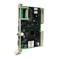
VIPA CP143 TCP/IP Manual (210 pages)
Brand:
VIPA
| Category:
Control Unit
| Size: 3 MB
Table of Contents
Table of Contents
5
Introduction
9
Handling Electrostatically Sensitive Modules
9
Safty and Handling Precautions for the User
9
Shipping Electrostatically Sensitive Modules
9
Tests and Modifications to Electrostatic Sensitive Modules
9
1 Introduction
11
Shipping Electrostatically Sensitive Modules
12
General
13
Fig. 1-1: Construction of the CP143 H1 or TCP/IP
13
Operation
14
Construction
14
2 Communication Protocols
15
H1 Protocol
15
Structure of Industrial Ethernet H1
15
Operation
18
Structure and Operation of the PLC Interface
18
Fig. 2-1: Example for the Cabling of the Industrial Ethernet H1 LAN
18
TCP/IP Protocol
19
Fig. 2-1: ISO-OSI Level Model
19
TCP/IP Principle of Operation
23
TCP/IP Services
23
3 Network Planning
25
Ethernet Network-Terminology
25
Fig. 3-1: Parts of an Ethernet Network
27
Thin-Ethernet-Cable Networks
29
Fig. 3-2: Thin Ethernet Network Hardware
30
Thin-Ethernet-Cable Network-Layout
31
Fig. 3-3: Example for a Thin-Ethernet Cable Network
31
Regulations and Specifications
32
Technical Data Thin-Ethernet
33
Thick-Ethernet-Cable Networks
34
Fig. 3-4: Thick-Ethernet Network Hardware
35
Thick-Ethernet-Cable Network-Layout
36
Fig. 3-5: Example for a Thick-Ethernet Network
36
Regulations and Specifications
37
Technical Data Thick-Ethernet
39
Combining Thin/Thick Ethernet Cable in Networks
40
Combination of Thin/Thick Ethernet Cable Hardware
40
Fig. 3-6: Adapters for Linking Unlike Segments
40
Thin/Thick Ethernet Cable Combination Network-Layout
41
Fig. 3-7: Example of a Network Combining Thin and Thick Ethernet Cable
41
Twisted Pair
42
Twisted Pair-Cable Network-Layout
42
Fig. 3-8: Star Topology of a Twisted Pair Network
42
Fig. 3-9: Twisted Pair Network Hardware
43
Planning a Network-Layout
44
Standards and Specifications
45
4 The Cp143 H1 / Tcp/Ip Network Board
47
The Construction of the Module
47
Components of the Module
47
Fig. 4-1: Construction of the CP143 H1 / TCP/IP
49
Jumper Settings
51
Fig. 4-2: Location of Jumpers
51
Sockets and Plugs
53
Fig. 4-3: Front View CP143 H1 / TCP/IP
53
Tab. 4-1: Pin Configuration of the 15-Pole AUI-/TP Socket
54
Tab. 4-2: Pin Configuration of the PG Interface
55
Tab. 4-3: Configuration of the TP Socket (RJ45)
55
The Cp143Plus Firmware
58
Components
58
The Structure of the Cp143Plus
59
Fig. 4-4: the Structure of the Cp143Plus
59
Further Information on the Cp143Plus
60
Tab. 4-4: Block Size
61
CP143 TCP/IP Firmware
62
Components
62
The Structure of the CP143 TCP/IP
63
Fig. 4-5: the Structure of the CP143 TCP/IP
63
Further Information on the CP143 TCP/IP
64
Fig. 4-6: Conversion of Ethernet Address into an IP Address
65
Tab. 4-5: Block Size
65
Organization Format (ORG Format)
66
Tab. 4-6: Organization Format
66
Tab. 4-7: ORG-Formats for Plcs (ORG Identifier 01H-04H)
66
Tab. 4-8: ORG-Formats for Plcs (ORG-Identifier 05H-08H)
67
Tab. 4-9: ORG-Formats for Plcs (ORG-Identifier 09H-11H)
67
Structure of the PLC-Header
68
Status- and Error Indicators
70
Fig. 4-7: the Structure of the Indicator Word ANZW
70
Tab. 4-10:Indicator Word Conditions for SEND
76
Tab. 4-11:Indicator Word Conditions for RECEIVE
76
Tab. 4-12:Indicator Word Conditions for READ/WRITE-AKTIV
76
Tab. 4-13:Indicator Word for SEND with an HTB-Identifier "NN
77
Tab. 4-14:Indicator Word for RECEIVE with an HTB-Identifier "NN
77
Fig. 4-8: Parameter Error Byte PAFE
78
5 Software
79
General
79
Installing and Starting the Program
79
Overview of Available Functions
79
Fig. 5-1: the Menu Structure of the Parameter Configuration Program
83
Using On-Line Help
85
The Base File
86
Loading, Saving and Deleting the Base File
86
Fig. 5-2: File Selection Window by Means of the Example for Load/Create
86
Printing the Base File
87
Fig. 5-3: Sample Base File in Text Form
87
Transferring the Base File
88
Fig. 5-4: Window for Remote Configuration
91
Initialization
93
CP Init
93
Fig. 5-5: CP-Base Initialization (Initial Initialization)
93
Online
95
Fig. 5-6: Parameters for Online Connections
95
System Configuration
96
Fig. 5-7: System Configuration Parameters
96
Real-Time Clock Functions
97
General
97
Graphic Representation of the Real-Time Clock Functions
97
Fig. 5-8: Graphic Representation of the Real-Time Clock Functions
97
Construction of a Synchronized System
98
Mechanism for Assigning the Master Clock
98
Fig. 5-9: Construction of a Synchronized System
98
Master Clock Initialization
99
Fig. 5-10: Master Clock Initialization
99
Important Considerations When Using Real-Time Clock Functions
101
Setting and Interrogating the Clock from the PLC
101
Test Functions for the Clock
103
Fig. 5-11: Dialog Window for the Test Functions for the Clock
103
Configuration of Connections
105
Structure of the Configuration Windows
105
Fig. 5-12: Structure of Configuration Windows
105
The Control Field of the Configuration Window
106
Fig. 5-13: Control Field of a Parameter Configuration Window
106
Indirect Addressing
107
Fig. 5-14: Indirect Addressing for TCP
107
Tab. 5-1: Possible Entries for Source/Destination with Indirect Addressing
107
Tab. 5-2: Data Word for the Indicator Word for Indirect Addressing
108
Multi-Connections
109
Fig. 5-15: Interactive Window for Multi-Connections
109
List of Connections
111
Fig. 5-16: List of Connections
111
Clearing All Connections
112
General Test Functions
113
Ident
113
Fig. 5-17: Display Window for Ident Parameters
113
Anzw Dump
114
Fig. 5-18: Output Window of Anzw Dump
114
Overall Status Functions
116
Fig. 5-19: Structure Overall Status Window
116
Tab. 5-3: Status of a Connection
119
Tab. 5-4: Status of Job Processing
119
Fig. 5-20: CP-Base Initialization (Initial Initialization)
122
Fig. 5-21: H1 Transport Parameters
124
Application in Combination with H1
126
Configuration of H1 Connections
126
Fig. 5-22: Interactive Window H1 Connections
127
Fig. 5-23: Interactive Window H1 Datagram-Connections
129
Test Functions
132
Fig. 5-24: Test Function under H1
132
Application in Combination with TCP/IP
133
Initialization
133
Fig. 5-25: CP Base Initialization (Initial Initialization)
133
Fig. 5-26: IP Transport-Parameters
135
Configuration of TCP/IP-Connections
136
Fig. 5-27: Interactive Window TCP-Connection
137
Fig. 5-28: Unspecified Configuration Options for TCP/IP
141
Fig. 5-29: Interactive Window UDP-Connection
142
Test Functions
145
Fig. 5-30: Test Function under TCP/IP
145
Onnet-Kernel for TCP/IP of Ftp
146
Microsoft Kernel for TCP/IP under WINDOWS 95/NT
149
Test Program for TCP/IP-Connections
150
Fig. 5-31: Test Program "Connect
150
Fig. 5-32: Test Program "Connect
151
Fig. 5-33: Test Program "Read a
152
Fig. 5-34: Test Program "Writea" Tab
153
Fig. 5-35: Test Program "Receive
154
Fig. 5-36: Test Program "Send
155
Fig. 5-37: Test Program "System
156
Accessing the PLC from the PC
157
6 Commissioning
159
Plug-In Slots in the PLC
159
Plug-In Slots in the AG-115U
159
Fig. 6-1: Plug-In Slots in the AG-115U
161
Plug-In Slots in the AG-135U
162
Fig. 6-2: Plug-In Slots in the AG-135U
162
Plug-In Slots in the AG-150U
163
Fig. 6-3: Plug-In Slots in the AG-150U
163
Plug-In Slots in the AG-155U
164
Fig. 6-4: Plug-In Slots in the AG-155U
164
Plug-In Slots in the EG-185U
165
Fig. 6-5: Plug-In Slots in the EG-185U
165
Plug-In Slots in the AG-188U
166
Fig. 6-6: Plug-In Slots in the AG-188U
166
Start-Up Properties
167
Status after the CP Has Started
167
Status Indicators
168
Tab. 6-1: Status Indicators
168
PLC Programming
169
General
169
Tab. 6-2: Handler Modules Required for the PLC
169
Tab. 6-3: HTB Numbers for the Different Types of CPU
169
Programming
170
Example
171
Overview and Conditions
171
Problem
172
Fig. 6-7: System Structure for the Introductory Example Using H1
172
Fig. 6-8: System Structure for the Introductory Example Using TCP/IP
172
Programs for the Plcs
174
Module Configuration under H1
181
Fig. 6-9: Initial Display of the Configuration Program
181
Fig. 6-10: CP Initialization Station 1 for H1
182
Fig. 6-11: CP Initialization Station 2 for H1
182
Fig. 6-13: H1 Connection Parameters Station 1
183
Fig. 6-15: Serial Configuration
185
Module Configuration under TCP/IP
186
Fig. 6-16: Start-Up Screen of the Configuration Program
186
Fig. 6-17: CP Initialization Station 1 for TCP
187
Fig. 6-18: CP Initialization Station 2 for TCP
187
Fig. 6-20: TCP Connection Parameters Station 1
188
Fig. 6-22: Remote Configuration
190
Monitoring the Transfer by Means of the MC5 Package
191
Fig. 6-23: Display of the Send Job in the MC5 Package
192
Fig. 6-24: Display of the Receive Job in the MC5 Package
192
Appendix
195
A Technical Data
195
B Error Messages from the NCS Configuration Program
197
C List of Abbreviations
201
D List of Figures
203
F Index
207
Rev. 00/07
207
Rev. 00/07
209
Advertisement
Advertisement
Related Products
VIPA CP143plus
VIPA CPU Series
VIPA CPU 214
VIPA CPU 21 Series
VIPA CPU 214DP
VIPA CPU 215DPM
VIPA CPU 216DPM
VIPA CPU 216CAN
VIPA CPU 312SC
VIPA CPU 216DP
VIPA Categories
Touch Panel
Control Unit
Control Systems
Controller
Computer Hardware
More VIPA Manuals
Login
Sign In
OR
Sign in with Facebook
Sign in with Google
Upload manual
Upload from disk
Upload from URL