Table of Contents
Advertisement
Quick Links
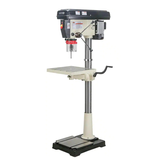
MODEL M1039
12-SPEED DRILL PRESS
OWNER'S MANUAL
(FOR MODELS MANUFACTURED SINCE 09/17)
184841
Phone: (360) 734-3482 • On-Line Technical Support: tech-support@shopfox.biz
COPYRIGHT © FEBRUARY, 2006 BY WOODSTOCK INTERNATIONAL, INC. REVISED JULY, 2018 (ABKB)
WARNING: NO PORTION OF THIS MANUAL MAY BE REPRODUCED IN ANY SHAPE OR FORM WITHOUT
THE WRITTEN APPROVAL OF WOODSTOCK INTERNATIONAL, INC.
Printed in China
#7894JK
Advertisement
Table of Contents

Related Manuals for Shop fox M1039


Summary of Contents for Shop fox M1039
- Page 1 MODEL M1039 12-SPEED DRILL PRESS OWNER'S MANUAL (FOR MODELS MANUFACTURED SINCE 09/17) 184841 Phone: (360) 734-3482 • On-Line Technical Support: tech-support@shopfox.biz COPYRIGHT © FEBRUARY, 2006 BY WOODSTOCK INTERNATIONAL, INC. REVISED JULY, 2018 (ABKB) WARNING: NO PORTION OF THIS MANUAL MAY BE REPRODUCED IN ANY SHAPE OR FORM WITHOUT THE WRITTEN APPROVAL OF WOODSTOCK INTERNATIONAL, INC.
- Page 2 This manual provides critical safety instructions on the proper setup, operation, maintenance, and service of this machine/tool. Save this document, refer to it often, and use it to instruct other operators. Failure to read, understand and follow the instructions in this manual may result in fire or serious personal injury—including amputation, electrocution, or death.
-
Page 3: Table Of Contents
Contents INTRODUCTION........2 MAINTENANCE........27 Woodstock Technical Support ....2 General .......... 27 Machine Specifications ......3 Cleaning ......... 27 Controls and Features ......5 Table, Column, & Base ......27 Lubrication ........27 SAFETY..........6 V-Belts ........... 27 Standard Machinery Safety Instructions ..6 SERVICE.......... -
Page 4: Introduction
M1039 12-Speed Drill Press INTRODUCTION Woodstock.Technical.Support This machine has been specially designed to provide many years of trouble-free service. Close attention to detail, ruggedly built parts and a rigid quality control program assure safe and reliable operation. Woodstock International, Inc. is committed to customer satisfaction. Our intent with this manual is to include the basic information for safety, setup, operation, maintenance, and service of this product. -
Page 5: Machine Specifications
Switch Type............. Toggle Safety Switch w/Removable Key Motors Main Horsepower....................1.5 HP Phase....................Single‐Phase Amps....................18A/9.4A Speed....................1725 RPM Type................. TEFC Capacitor‐Start Induction Power Transfer ................... V‐Belt Drive Bearings............... Shielded & Permanently Lubricated Centrifugal Switch/Contacts Type..............Internal Model M1039 Machine Specifications, Page 1 of 3... - Page 6 Base Width................... 17‐1/2 in. Mobile Base..................... D2058A Column Diameter..................3.642 in. Depth Stop Type............Threaded Rod with Positive Stop Has Work Light....................Yes Light Socket Type................120V, Std Bulb Maximum Bulb Wattage.................. 60 W Model M1039 Machine Specifications, Page 2 of 3...
-
Page 7: Controls And Features
M1039 12-Speed Drill Press Controls.and.Features Figure.1. M1039 headstock controls. Figure.2. M1039 table controls. G. Belt Tension Lever A. Light Switch (120V only) H. Scale B. Power Switch C. Belt Tension Lock Table Height Crank Handle Small Lock Lever D. Torsion Spring K. -
Page 8: Safety
M1039 12-Speed Drill Press SAFETY SAFETY For.Your.Own.Safety, Read.Manual.Before.Operating.Machine The. purpose. of. safety. symbols. is. to. attract. your. attention. to. possible. hazardous. conditions.. This. manual.uses.a.series.of.symbols.and.signal.words.intended.to.convey.the.level.of.importance.of.the. safety.messages..The.progression.of.symbols.is.described.below..Remember.that.safety.messages.by. themselves. do. not. eliminate. danger. and. are. not. a. substitute. for. proper. accident. prevention. mea- sures—this.responsibility.is.ultimately.up.to.the.operator! - Page 9 M1039 12-Speed Drill Press WEARING.PROPER.APPAREL..Do not wear FORCING.MACHINERY..Do not force machine. It clothing, apparel, or jewelry that can become will do the job safer and better at the rate for entangled in moving parts. Always tie back which it was designed.
-
Page 10: Additional Safety For Drill Presses
M1039 12-Speed Drill Press Additional.Safety.for.Drill.Presses WEARING.PROPER.APPAREL..Do not wear FORCING.MACHINERY..Do not force machine. It clothing, apparel, or jewelry that can become will do the job safer and better at the rate for entangled in moving parts. Always tie back which it was designed. -
Page 11: Electrical
M1039 12-Speed Drill Press ELECTRICAL Circuit.Requirements This machine must be connected to the correct size and type of power supply circuit, or fire or electrical damage may occur. Read through this section to determine if an The. machine. must. be. properly. set. up. -
Page 12: Grounding Requirements
M1039 12-Speed Drill Press Grounding.Requirements This machine MUST be grounded. In the event of certain types of malfunctions or breakdowns, grounding provides a path of least resistance for electric current to travel—in The. machine. must. be. properly. set. up. order to reduce the risk of electric shock. -
Page 13: Setup
M1039 12-Speed Drill Press SETUP Unpacking This machine has been carefully packaged for safe transportation. If you notice the machine has been damaged during shipping, please contact your authorized Shop Fox dealer immediately. Inventory The following is a list of items shipped with your machine. -
Page 14: Machine Placement
M1039 12-Speed Drill Press Machine.Placement Weight.Load Physical.Environment Refer to the Machine.Specifications for the The physical environment where your machine is weight of your machine. Make sure that the operated is important for safe operation and the surface upon which the machine is placed will longevity of its components. -
Page 15: Anchoring To Floor
M1039 12-Speed Drill Press Anchoring.to.Floor Number.of.Mounting.Holes........4 Diameter.of.Mounting.Hardware......⁄ " Lag Screw Anchoring machinery to the floor prevents tipping or shifting and reduces vibration that may occur during operation, resulting in a machine that runs slightly quieter Flat Washer and feels more solid. -
Page 16: Assembly
M1039 12-Speed Drill Press Assembly Before beginning the assembly process, refer to Items. Needed.for.Setup and gather everything you need. Ensure all parts have been properly cleaned of any Hex Bolts heavy-duty rust-preventative applied at the factory (if applicable). Be sure to complete all steps in the assembly procedure prior to performing the Test.Run. - Page 17 M1039 12-Speed Drill Press 4. Place the rack inside of the table bracket, mesh it together with the pinion, and slide the table support/rack assembly over the column, as shown in Figure.11. 5. Slide the column ring over the column with the beveled edge facing down (Figure.12), fit the...
-
Page 18: Headstock
M1039 12-Speed Drill Press Headstock The headstock must be mounted on the column/base assembly before the drill press can be operated. Moving and installing the headstock is a two-person job, at the very least. Although the headstock can be lifted directly... -
Page 19: Drill Chuck And Arbor
M1039 12-Speed Drill Press Drill.Chuck.and.Arbor Chuck Key MT4/JT3 Arbor The drill chuck attaches to the spindle by means of the arbor, shown in Figure.17. Matched tapers on the arbor and the inside of the chuck create a semi-permanent assembly when properly joined. -
Page 20: Downfeed Handles And Belt Cover Knob
The table should now be installed as shown in Figure.21. Light.(120V.Only) Figure.21. Table installed. The Model M1039 includes a light socket, designed.for. 120V.use.only. When the drill press is shipped from the factory, a dust plug is installed in the socket. To.install.a.light.bulb.in.the.drill.press,.do.these.steps: 1. -
Page 21: Test Run
M1039 12-Speed Drill Press Test.Run Once assembly is complete, test run the machine to Serious. injury. or. death. can. result. ensure it is properly connected to power and safety from. using. this. machine. BEFORE. components are functioning properly. understanding. its. controls. and. related. -
Page 22: Operations
M1039 12-Speed Drill Press OPERATIONS General The Model M1039 will perform many types of operations that are beyond the scope of this manual. Many of these operations can be dangerous or deadly if performed incorrectly. The instructions in this section are written with the understanding that the operator has the necessary knowledge and skills to operate this machine. -
Page 23: Choosing Speeds
M1039 12-Speed Drill Press Choosing.Speeds Using.the.Drill.Bit.Speed.Charts Always.ensure.bits.are.installed.prop- The charts shown on Page.22 & Page.23.are intended erly.BEFORE.turning.the.machine.ON.. Failure.to.follow.correct.drill.bit.instal- as guides only. Always follow the manufacturer's speed lation. procedures. can. lead. to. serious. recommendations if provided with your drill bits, cutters, or hole saws. Exceeding the recommended speeds may be personal.injury. - Page 24 M1039 12-Speed Drill Press ......-22-...
- Page 25 M1039 12-Speed Drill Press MODEL M1039 12 SPEED DRILL PRESS SPINDLE SPEED SETTINGS (RPM) 1 180 RPM BELT A-4 2 300 RPM BELT B-4 3 390 RPM BELT A-3 4 420 RPM BELT C-4 5 600 RPM BELT B-3 6 640 RPM BELT A-2...
-
Page 26: Drilling
Refer to the Drill.Bit.Speed.Charts on Page.22 & Page.23.to help you choose the correct speed for your application. Depth.Stop The Model M1039 has a depth stop that allows you to drill repeated non-through holes of same depth every time. Upper Depth Nut... -
Page 27: Adjusting Table
M1039 12-Speed Drill Press 3. Lower the upper jam nut against the depth nut. 4. Using wrenches, hold the depth nut in place and tighten the upper jam nut against the depth nut. Note: The scale on the depth stop can be recalibrated if it gets moved or has changed since the factory setting. -
Page 28: Arbor Removal
M1039 12-Speed Drill Press Arbor.Removal The arbor can be removed to install other Morse Taper tooling in the spindle. A drift key is included to help remove the arbor or other tooling from the spindle. Both Slots Usually, once the chuck and arbor have been properly... -
Page 29: Maintenance
M1039 12-Speed Drill Press MAINTENANCE General SHOP FOX Regular periodic maintenance on your ® Model M1039 will ensure its optimum performance. Make a habit of inspecting your machine each time you use it. Check.for.the.following.conditions.and.repair.or. replace.when.necessary: • Loose mounting bolts. •... -
Page 30: Service
M1039 12-Speed Drill Press SERVICE General This section covers the most common service adjustments or procedures that may need to be made during the life of your machine. If you require additional machine service not included in this section, please contact Woodstock International Technical Support at (360) 734-3482 or send e-mail to: tech-support@shopfox.biz. -
Page 31: Feed Shaft Spring Tension
M1039 12-Speed Drill Press Feed.Shaft.Spring.Tension The feed shaft return spring is adjusted at the factory; however, during the life of the drill press you may want to adjust the feed shaft return spring so the return pressure suits your operating needs. -
Page 32: Electrical Safety Instructions
M1039 12-Speed Drill Press Electrical.Safety.Instructions These pages are current at the time of printing. However, in the spirit of improvement, we may make changes to the electrical systems of future machines. Compare the manufacture date of your machine to the one stated in this manual, and study this section carefully. -
Page 33: Electrical Components
M1039 12-Speed Drill Press Electrical.Components Figure.34. Power and light switch wiring. Figure.36. Motor junction box wiring. Figure.35. 120V light socket. Figure.37. Wiring diagram on inside of junction box cover. -31-... -
Page 34: Wiring Diagram
M1039 12-Speed Drill Press Wiring.Diagram MOTOR Prewired (120V) Ground Ground MOTOR Rewired (240V) Ground Rewired to 240V Ground 120 VAC 240 VAC 5-20 Plug 6-15 Plug (Installed) (As Recommended) -32-... -
Page 35: Troubleshooting
M1039 12-Speed Drill Press Troubleshooting This section covers the most common problems and corrections with this type of machine. WARNING!.DO.NOT.make.any.adjustments.until.power.is.disconnected.and. moving.parts.have.come.to.a.complete.stop! PROBLEM POSSIBLE.CAUSE CORRECTIVE.ACTION Machine does not Plug or receptacle at fault or wired Test power plug and receptacle for good contact start or a breaker incorrectly. - Page 36 M1039 12-Speed Drill Press PROBLEM POSSIBLE.CAUSE CORRECTIVE.ACTION Chuck wobbles or Foreign material is stuck between Remove chuck and clean and de-burr tapered is loose on spindle chuck-to-spindle mating surface. chuck and spindle mating surfaces, then shaft. reassemble. Damaged chuck. Replace.
-
Page 37: Parts
M1039 12-Speed Drill Press PARTS Table.&.Column -35-... -
Page 38: Headstock
M1039 12-Speed Drill Press Headstock 67-5 67-4 67-2 67-1 67-3 23V2 24V2 26V2 184841 78-1 78-2 79V2 26-1 78-3 31V2 26-2 95-1 128-3 128-1 128-5 128-2 128-4 -36-... - Page 39 XM1039021 DP LIGHTS LABEL XM1039068 NUT M12-1.75 XM1039022 SHOP FOX BLACK/AL LABEL XM1039069 FLAT WASHER 12MM 23V2 XM1039023V2 SPEED CHART M1039 V2.01.18 XM1039070 MOTOR BASE 24V2 XM1039024V2 MACHINE ID LABEL CSA V2.01.18 XM1039071 SLIDE BAR (RIGHT) XM1039025 SLEEVE MT#4 XM1039072 SLIDE BAR (LEFT) 26V2 XM1039026V2 POWER CORD 3W 14G 72"...
- Page 40 M1039 12-Speed Drill Press Parts.List.(Cont.) REF PART # DESCRIPTION PART # DESCRIPTION XM1039096 STAFF GAUGE XM1039119 HANDLE XM1039097 FEED HANDLE KNOB M12-1.75 XM1039120 TABLE BRACKET XM1039098 HANDLE XM1039121 COLUMN XM1039099 HANDLE BODY XM1039122 RACK XM1039100 KEY 6 X 6 X 20 XM1039123 HEX BOLT M12-1.75 X 40...
- Page 42 Fold along dotted lIne place stamp Here Woodstock international inc. p.o. box 2309 bellingham, Wa 98227-2309 Fold along dotted lIne tape along edges--please do not staple -40-...
-
Page 43: Warranty
Woodstock International, Inc. will repair, replace, or arrange for a dealer refund, at its expense and option, the Shop Fox machine or machine part proven to be defective for its designed and intended use, provided that the original owner returns the product prepaid to an authorized warranty or repair facility as designated by our Bellingham, Washington office with proof of their purchase of the product within two years, and provides Woodstock International, Inc.
Need help?
Do you have a question about the M1039 and is the answer not in the manual?
Questions and answers