Advertisement
Quick Links
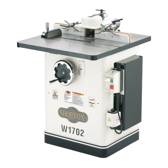
Model W1702
***IMPORTANT UPDATE***
Applies to Models Mfd. Since 08/10
Phone #: (360) 734-3482 • Tech Support: techsupport@woodstockint.com • Web: www.woodstockint.com
We recently made changes to the Model W1702 3HP Shaper for CSA certification. As a result, the
electrical requirements, specifications, and some parts shown in the original manual no longer match
what is currently on the machine.
This manual update provides new power requirements, specifications, and parts information that reflect
the changes. At the top of the following pages, the header indicates which page it replaces in the
original manual. All changes indicated in this update are effective for machines manufactured since
August, 2010.
Before operating your new shaper, you MUST read and understand this manual insert AND the original
manual to reduce the risk of injury from improper use or setup. Since this insert covers changes made to
the machine after the owner's manual was printed, you MUST keep this insert with your owner's manual
for future reference.
If you have any questions, contact Tech Support at (360) 734-3482 or by emails at techsupport@
woodstockint.com.
Figure 1. Model W1702 3HP Shaper
COPYRIGHT © SEPTEMBER, 2010 BY WOODSTOCK INTERNATIONAL, INC., REVISED 01/17 (JH)
WARNING: NO PORTION OF THIS MANUAL MAY BE REPRODUCED IN ANY SHAPE OR FORM WITHOUT
THE WRITTEN APPROVAL OF WOODSTOCK INTERNATIONAL, INC.
#13142TS Printed in Taiwan
177335
Advertisement

Related Manuals for Shop fox W1702


Summary of Contents for Shop fox W1702
- Page 1 Phone #: (360) 734-3482 • Tech Support: techsupport@woodstockint.com • Web: www.woodstockint.com We recently made changes to the Model W1702 3HP Shaper for CSA certification. As a result, the electrical requirements, specifications, and some parts shown in the original manual no longer match what is currently on the machine.
- Page 2 Model W1702 Manual Insert (Mfd. Since 8/10) (Replaces Specifications on Page 3) MODEL W1702 3 HP SHAPER Product Dimensions Weight......................352 lbs. Width (side‐to‐side) x Depth (front‐to‐back) x Height......30‐1/2 x 28‐1/4 x 39‐1/2 in. Footprint (Length x Width)................20 x 21 in.
- Page 3 Fence..................Cast Iron with Wood Miter Gauge................... Cast Iron Guard....................Cast Iron Spindle Bearings..............Shielded & Lubricated Paint Type/Finish................Powder Coated Other Number of Dust Ports..................1 Dust Port Size....................3 in. Mobile Base..................... D2057A Model W1702 Machine Specifications, Page 2 of 3...
- Page 4 Model W1702 Manual Insert (Mfd. Since 8/10) Power Supply (Replaces Page 8) Availability Circuit Information Before installing this machine, consider the A power supply circuit includes all electrical availability and proximity of the required power equipment between the main breaker box or fuse supply circuit.
- Page 5 Model W1702 Manual Insert (Mfd. Since 8/10) Grounding Requirements Improper connection of the equipment-grounding wire can result in a risk of electric shock. The In the event of certain types of malfunctions or wire with green insulation (with or without breakdowns, grounding provides a path of least yellow stripes) is the equipment-grounding wire.
- Page 6 Model W1702 Manual Insert (Mfd. Since 8/10) New Machine Inventory (Figure ??) • Front Safety Shield ........1 • Clear Guard ..........1 • Knob Bolt ⁄ "-20 x ⁄ " ........2 • Flat Washer ⁄ " ..........4 Figure 4. New machine inventory items.
-
Page 7: Forward/Reverse Switch
(Replaces Page 23) Forward/Reverse Cutter Direction Switch The Model W1702 is capable of operating in two directions by use of a forward/reverse switch as shown in Figure 3 . It is very important that the workpiece be fed against the direction of the cutter rotation. - Page 8 Updated Wiring Diagram (Replaces Page 35) SDE MA-15 Start Capacitor 400 MFD 125V Relay SDE RA-20...
-
Page 9: Electrical Components
Electrical Components Figure 7. Magnetic switch. Figure 9. Updated motor wiring. Figure 8. Updated motor start capacitor. Figure 10. Forward/reverse switch wiring. - Page 10 Model W1702 Manual Insert (Mfd. Since 8/10) Main Parts Diagram (Replaces Page 36) 33V2-1 33V2-2 33V2 46V2 35V3 601A 69V2 78V2 -10-...
- Page 11 Model W1702 Manual Insert (Mfd. Since 8/10) Main Parts List (Replaces Page 37) PART # DESCRIPTION REF PART # DESCRIPTION X1702001 STAND XPCAP77 CAP SCREW 3/8-24 X 1 X1702002 TABLE WING X1702056 FENCE ADJ SCREW XPS07 PHLP HD SCREW 1/4-20 X 3/8...
- Page 12 Motor Diagram (Replaces Page 38) 152-1V2 145-5 145-3 145-4 145-2 -12-...
- Page 13 Main Parts List (Replaces Page 39) REF PART # DESCRIPTION PART # DESCRIPTION X1702101 HANDLE X1702133 L-BRACKET X1702102 HANDWHEEL X1702134 POINTER X1702103 HEX BOLT 5/16-18 X 1/2 X1702135 FLAT WASHER 5/16 X1702104 SET SCREW 3/8-16 X 3/8 X1702136 ELEVATION LEADSCREW X1702105 SET SCREW 5/16-18 X 1/2 X1702137...
- Page 14 Model W1702 Manual Insert (Mfd. Since 8/10) Safety Guard Parts (Replaces Pages 42–43) 315V2 316V2 PART # DESCRIPTION PART # DESCRIPTION XPSS02 SET SCREW 5/16-18 X 3/8 X1674414 EXTENSION BAR X1674402 SHAFT MOUNT 315V2 X1702315V2 OVERHEAD SAFETY GUARD V2.08.10 XPLW04...
- Page 15 Motor Brace Removal Model W1674/W1702 A motor brace is factory installed on the Model W1674/W1702 to prevent damage to the motor during shipping. This motor brace must be removed before operation. To remove the motor brace, do these steps: 1. Remove the three hex bolts, shown in...
- Page 16 This update covers the changes to the machine, or any critical information that may be missing from the original W1702 manual. This update is intended to be used WITH the original manual, not as a replace- ment for it. Before operating your new shaper, you MUST read and understand the entire W1702 manual.
- Page 17 W1702 Manual Update New Machine Inventory • Shaper Unit ..........1 • Extension wing ..........1 Box #1 • Magnetic Switch ...........1 • FWD/REV Switch ...........1 Box #2 • Fence Housing Assembly .........1 • Wood Fence Faces .........2 • Plastic Fence Faces ........2 •...
- Page 18 W1702 Manual Update Attaching Switches To install the switches, do these steps: 1. Remove the motor cover from the cabinet by remov- ing the six screws that hold it in place. 2. Remove the switches from inside the cabinet. 3. Install the grommet plate on to the motor cover as shown in Figure 4.
- Page 19 Figure 8. All Other Assembly All other assembly to the machine MUST be performed as described in the W1702 Manual. If you have any questions Cap Screws that cannot be answered reading this manual update or the full W1702 manual, please contact our Technical Figure 8.
- Page 21 Some dust created by power sanding, sawing, grinding, drilling, and other construction activities contains chemicals known to the State of California to cause cancer, birth defects or other reproductive harm. Some examples of these chemicals are: • Lead from lead-based paints. •...
- Page 23 Close attention to engineering detail, ruggedly built parts, and a rigid quality control program assure safe and reliable operation. The Model W1702 features a 3 HP, 220V single-phase motor with forward/reverse spindle control. Also included are a heavy-duty miter gauge, fence with safety guard, cast iron handwheel, large precision ground cast iron table, and all ball bearing construction.
- Page 24 ® Woodstock International, Inc. warrants all machinery to be free of defects from workmanship and materials for a period of 2 years from the date of original purchase by the original owner. This warranty does not apply to defects due directly or indirectly to misuse, abuse, negligence or accidents, lack of maintenance, or to repairs or alterations made or specifically authorized by anyone other than Woodstock International, Inc.
- Page 25 Indicates an imminently hazardous situation which, if not avoided, WILL result in death or serious injury. Indicates a potentially hazardous situation which, if not avoided, COULD result in death or serious injury. Indicates a potentially hazardous situation which, if not avoided, MAY result in minor or moderate injury.
- Page 26 with padlocks, master switches or by removing starter keys. The machine will do a safer and better job at the rate for which it was designed. force machine or attachment to do a job for which it was not designed. wear loose clothing, neck ties, gloves, jewelry, and secure long hair away from moving parts.
- Page 27 of the cutters. Never pass your hands directly over or in front of the cutter. As one hand approaches the 12-inch radius point, move it in an arc motion away from the cutter to the outfeed side and reposition that hand more than 12 inches beyond the cutter.
- Page 28 : Guard Removed for Clarity. Always Use Guard. ® Use a Featherboard as ® BOARD BUDDIES ® anti-kick back protection. holding down the workpiece. : Guard Removed for Clarity. Always Use Guard. ® Use a Right Angle Jig Use rubberized ®...
- Page 29 ® Model W1702 Shaper 220 volt motor draws approximately 18 amps. Purchase a NEMA-style 6-20 plug and receptacle for the power supply circuit connection. Since other machines may be using the same circuit, make sure the circuit, circuit breaker, or fuse can carry a 20 amp load. If the total...
- Page 30 The Model W1702 is carefully packed. However, if it is damaged or is missing any parts, please contact Woodstock International Service and Support at 1-360-734-3482 or send e-mail to: tech-support@shopfox.biz. Layout and inventory the shipped parts to familiarize yourself with your Model W1702 Shaper.
- Page 31 ® While the main components of the The exposed and unpainted shaper surfaces are Model W1702 are assembled at the factory, some coated with a waxy oil to prevent rust during assembly is required including shop preparation. storage and shipment. DO NOT use chlorine...
- Page 32 Model W1702 3 HP clearances and airflow. Connect a 3" flexible dust Shaper out of the way when not in use.
- Page 33 Fence facing can be custom made for special needs—for example, mounting a hold-down ® roller systems like the Model ® W1105 Green BOARD BUDDIES Using ⁄ "-20 x ⁄ " Countersunk Phillips ® head screws, ⁄ " washers, and ⁄ "-20 T-nuts;...
- Page 34 The hold-downs hold the workpiece against the fence and the table. NOTE: Remove the hold- down assembly when not in use. Install two aluminum hold-down brackets onto each of the hold-down bars as shown in Insert the long end of the hold-down bar through the hole in the fence mount as shown in Adjust the hold-down fence mount to the...
- Page 35 Spindle The Model W1702 comes with ⁄ ", ⁄ ", and 1" shaper spindles. Also available is a Model D3392 Optional Router Bit Spindle. It is very important that any spindle you use, is seated securely into the shaper so that safety is maintained.
- Page 36 Thread the tapered drawbar nut onto the end of the drawbar under the table, and make sure that the taper side of the nut is facing upward as shown in Tighten your selected spindle in the shaper as outlined below: Place the spindle wrench on the top end of the spindle.
- Page 37 The two fence faces are independently adjustable to allow for different shaping tasks. The fence faces can be set at different positions to remove material from the entire edge of the wood stock or the same position to allow the shaping of part of the edge.
- Page 38 Before shaping, check that the two fence faces are parallel. Get a quality straightedge that is long enough to span the entire length of the fence assembly. Make sure that the screws that hold the fence faces to the fence mounts are tight and secure.
- Page 39 The table inserts are necessary for the safe operation of the shaper. Two inserts are provided allowing for three different opening sizes to be achieved. Use the smallest-size opening for a cutter to reduce wood chips falling into the machine, which could cause flying debris. Using the smallest-size opening also covers any unused portion of the bit below the surface of the table, thus reducing the chance of operator injury.
- Page 40 Pulley alignment is important to the performance of your shaper. If the pulleys are just slightly out of alignment, the shaper may suffer from power loss as well as decreased V-belt life. The pulleys need to be parallel with one another for optimum shaper performance.
- Page 41 This shaper spindle can be run at 7,000 or 10,000 RPM. The speed is changed by the placement of the V-belt as shown in Always follow cutter manufacturer recommendations; however, if not available use these general specifications to help select spindle and RPM.
- Page 42 The spindle slide-to-gib clearance may need adjusting so there is no play when pressure is applied to the spindle. Gib adjustments are made by loosening or tightening some or all of the four setscrews on the side of the elevation housing shown in Turn the handwheel until the spindle is in the NOTICE...
- Page 43 Once assembly is complete and adjustments have been made, the shaper is ready for start up. Always pay attention to any unusual noises and vibrations on every start up, as well as make sure the shaper operates as intended. that the fence, any accessories, Jigs, spindle, cutter, or router bit adapter being used is tight and no loose items are on the table.
- Page 44 The Model W1702 is capable of operating in two directions by use of a forward and reverse switch as shown in It is very important that the workpiece be fed against the direction of the cutter rotation. This will prevent a climb cut and maintains a safe cutting procedure for the operator.
- Page 45 Always follow cutter manufacturer recommendations; however, if not available use the list below with your particular cutting needs in mind to help select the correct cutter, spindle, and RPM. Then install your cutter as outlined. elect your cutter, bushings, and rub collars.
- Page 46 Place the bushing (if needed) onto the spindle for cutter support as shown in Spindle washer placement. Slide the cutter onto the spindle, making sure the rotation is correct for the specific application as shown in Place the spindle washer onto the spindle as shown in Install spacers or collars if necessary for the specific application, followed by the nut and...
- Page 47 Tighten down the nut and locknut with an open-end wrench while holding the top of the spindle with the provided spindle wrench as shown in Make sure the cutter will rotate in the correct direction. NOTICE Go to the section on and set the spindle RPM as outlined.
- Page 48 Because the shaper fence is independently adjustable, you can set up the shaper to cut part or all of the workpiece edge. Fence mount lock handle. Loosen the locking handles shown on the sides of the fence mount in Turn the adjustment knob located on the back of the fence mount and adjust the infeed fence until the workpiece contacts the cutter at the desired location.
- Page 49 Loosen the lock handles on the side of the fence mount. Fence setup for partial-edge Turn the adjustment knob located on the removal operations back of the fence mount and adjust the (Guard Removed For Clarity). infeed fence until the workpiece contacts the cutter at the desired location.
- Page 50 When shaping workpieces that have irregular shapes, rub collars are a necessity. There are two types of rub collars: solid and ball bearing. They are available in various diameters and can be purchased individually or as sets as shown in Some examples of when you would use a rub collar are raising arched or tombstone door panels, round table tops, or any other cut...
- Page 51 Freehand shaping is shaping without the aid of the miter slot or fence. The most dangerous part of shaping freehand is beginning the cut, where the cutter first contacts the workpiece. Often the workpiece will tend to jerk or kickback, catching the operator off guard.
- Page 52 Sometimes the location of the starting pin holes will not always be in the safest position. You can clamp a piece of scrap wood to the shaper table. The edge of the wood can be used as the starting support as shown in The use of patterns (templates) allows identical parts to be cut with speed and accuracy.
- Page 53 Regular periodic maintenance on your Model W1702 Shaper will ensure optimum performance. Make a habit of inspecting your shaper each time you use it. Check for the following conditions and repair or replace parts when necessary. Loose mounting bolts. Worn switch.
- Page 54 -33-...
- Page 55 Trade drawings, and photographs illustrated in this journals, woodworking magazines, and your manual represent the Model W1702 3 HP Shaper local library are good places to start. as supplied when the manual was prepared.
- Page 56 -35-...
- Page 57 -36-...
- Page 58 PLASTIC FACING (RIGHT) 70 X1702070 ADJUSTMENT TUBE 22 X1702022 T-NUT 72 X1702072 COLOR STRIPE 23 X1702023 WOOD FACING 73 X1702073 LABEL (W1702) ⁄ "-20 x ⁄ " 25 XPSS04 SETSCREW 78 X1702035 MOTOR POWER CORD, 5 WIRE 28 XPW06 FLAT WASHER ⁄...
- Page 59 -38-...
- Page 60 101 X1702101 HANDLE 134 W1702134 POINTER 135 XPW07 FLAT WASHER ⁄ " 136 X1702036 ELEVATION LEAD SCREW 137 X1702137 CARTRIDGE SLIDE 138 XPB15 HEX BOLT ⁄ "-18 x ⁄ " 139 X1702146 V-BELT 7m690 141 XPB22 HEX BOLT ⁄ "-18 x 1 ⁄...
- Page 61 -40-...
- Page 62 REF# PART # DESCRIPTION REF# PART # DESCRIPTION XPR15M EXT RETAINING RING 30mm 234 X1702214A SPINDLE CARTRIDGE KIT X1702204 SPINDLE CARTRIDGE 236 X1702236 1" SPINDLE WASHER XPK20M KEY 5 x 5 x 15mm 237 X1702237 HOUSING CAP XP6205 BEARING 6205 ZZ 238 XPS01 PHLP HD SCR 10-24 x ⁄...
- Page 64 301 XPSS02 SETSCREW ⁄ "-18 x ⁄ " 310 X1702310 “T” HANDLE PEG 313 XPN02 HEX NUT ⁄ " - 18 302 X1702302 SHAFT MOUNT 314 X1702314 EXTENSION BAR 303 XPW02 LOCK WASHER ⁄ " 304 XPB18 HEX BOLT ⁄ "-16 x 1"...
- Page 65 -44-...
- Page 66 610 X1702610 603 X1702 603 MITER GAUGE BODY STOP 611 X1702611 604 X1702 604 POINTER MITER BAR 612 X1702612 605 X1702 605 SCALE SPECIAL WASHER 606 XPFH19 613 X1702613 GUIDE STUD FLAT HEAD SCREW ⁄ "-20 X ⁄ " 607 XPNO7 SPRING PIN 3 mm HEX NUT 10-24 614 X1702614...
- Page 67 401 X1702401 HOLD-DOWN BAR 402 X1702402 HOLD-DOWN 403 X1702403 BRACKET, HOLD-DOWN 404 XPSS02 SETSCREW ⁄ " - 18 x ⁄ " -46-...
- Page 68 The following shaper accessories may be available through your local Woodstock International Inc. Dealer. If you do not have a dealer in your area, these products are also available through online dealers. Please call or e-mail Woodstock International Inc. Customer Service to get a current listing of dealers at: 1-800 840-8420 or at sales@woodstockint.com.
- Page 69 and available knives let you cut many profiles for your projects. This system uses a wide variety of precision-ground cutter patterns for use in a specially-designed CNC-machined, aircraft aluminum cutterhead. The 2" moulding head accepts all 2" knives and works on shapers with 3/4" diameter spindles and motors 1-1/2 HP or larger.
- Page 72 ________________________________ __________________________ Name ___________________________________________________________________________________________ Street __________________________________________________________________________________________ City ___________________________________________________________________ State________Zip_________ Phone Number_______________________E-Mail_________________________________FAX___________________ _____________________ ___________________________________________________________ Where did you purchase your ® machine? How many ® machines do you own? _____________ _________________________________________________________ What stationary woodworking tools do you own? Check all that apply. ___Air Compressor ___Panel Saw How did you first learn about us?
- Page 73 FOLD ALONG DOTTED LINE Place Stamp Here FOLD ALONG DOTTED LINE TAPE ALONG EDGES--PLEASE DO NOT STAPLE...
Need help?
Do you have a question about the W1702 and is the answer not in the manual?
Questions and answers