Table of Contents
Advertisement
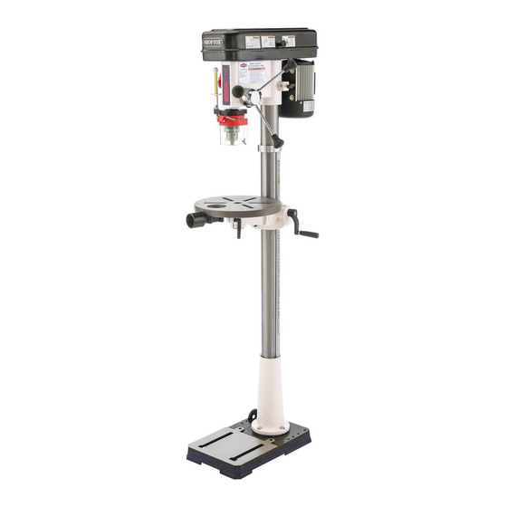
MODEL W1668/W1848
13
⁄
" OSCILLATING
1
4
DRILL PRESS
W1848
W1668
OWNER'S MANUAL
(FOR MODELS MANUFACTURED SINCE 08/16)
Phone: (360) 734-3482 • Online Technical Support: tech-support@shopfox.biz
COPYRIGHT © MARCH, 2017 BY WOODSTOCK INTERNATIONAL, INC.
WARNING: NO PORTION OF THIS MANUAL MAY BE REPRODUCED IN ANY SHAPE OR FORM WITHOUT
THE WRITTEN APPROVAL OF WOODSTOCK INTERNATIONAL, INC.
Printed in China
#18837MN
V2.03.17
Advertisement
Table of Contents


Need help?
Do you have a question about the W1668 and is the answer not in the manual?
Questions and answers