Table of Contents
Advertisement
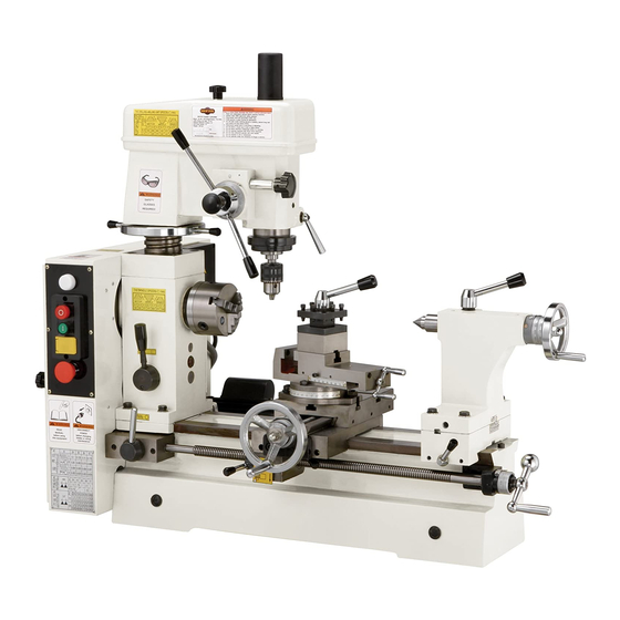
Model M1018
***IMPORTANT UPDATE***
Applies to Models Mfd. Since 11/13
and Owner's Manual Revised 03/09
Phone #: (360) 734-3482 • Tech Support: techsupport@woodstockint.com • Web: www.woodstockint.com
We made the following changes to this machine since the manual was printed:
•
ON/OFF button has changed.
•
FOR/REV switch has changed.
•
Wiring Diagram has been updated.
Aside from the information contained in this update, all other content in the owner's manual is
applicable and MUST be read and understood for your own safety.
IMPORTANT: Keep this update with the owner's manual for future reference. If you have any further
questions, contact our Technical Support.
Changed Control Panel Parts
48A
43V2-2
43V2-1
47
43V2
REF
PART #
43V2
XM1018043V2
43V2-1
XM1018043V2-1
43V2-2
XM1018043V2-2
46V2
XM1018046V2
48A
XM1018048A
62V2
XM1018062V2
COPYRIGHT © SEPTEMBER, 2017 BY WOODSTOCK INTERNATIONAL, INC.
WARNING: NO PORTION OF THIS MANUAL MAY BE REPRODUCED IN ANY SHAPE OR FORM WITHOUT
#19052JH
READ THIS FIRST
46V2
62V2
DESCRIPTION
SWITCH ASSEMBLY V2.11.13
ROTARY SWITCH KEDU ZH-A F/O/R
ON/OFF SWITCH KEDU KJD17B 120V
SWITCH MOUNTING PLATE V2.11.13
INDICATOR LIGHT ASSY
HEADSTOCK BOX V2.11.13
THE WRITTEN APPROVAL OF WOODSTOCK INTERNATIONAL, INC.
Printed in China
Advertisement
Table of Contents

Related Manuals for Shop fox M1018


Summary of Contents for Shop fox M1018
- Page 1 READ THIS FIRST Model M1018 ***IMPORTANT UPDATE*** Applies to Models Mfd. Since 11/13 and Owner's Manual Revised 03/09 Phone #: (360) 734-3482 • Tech Support: techsupport@woodstockint.com • Web: www.woodstockint.com We made the following changes to this machine since the manual was printed: •...
-
Page 2: Wiring Diagram
Model M1018 (Mfd. Since 11/13) Wiring Diagram Indicator Light Schneider XB7-EV41 ON/OFF Button Limit Switch OMRON Z-15GW22-B KJD17B 120V Rotary Switch KEDU ZH-A F/O/R E-Stop Button Schneider XB2 Motor Ground 110V Neutral 110 VAC 5-15 Plug (As Recommended) Ground... - Page 3 READ THIS FIRST Model M1018 ***IMPORTANT UPDATE*** Applies to Models Mfd. Since 09/16 and Owner's Manual Revised 03/09 Phone #: (360) 734-3482 • Tech Support: techsupport@woodstockint.com • Web: www.woodstockint.com We made the following changes to this machine since the manual was printed: •...
-
Page 6: Table Of Contents
Woodstock Technical Support ................3 About Your New Combo Lathe/Mill ..............3 Specifications ....................4 Controls and Features ..................5 Standard Safety Instructions ................6 Additional Safety Instructions for Lathe/Mill Combos ..........8 110V Operation ..................... 9 Extension Cords .................... 9 Electrical Specifications .................. - Page 7 General ....................38 Maintenance Schedule ................... 38 Lubrication ....................38 General ....................40 Adjusting Gibs .................... 40 Wiring Diagram ................... 42 Troubleshooting................... 43 Warranty Registration ................... 59...
- Page 8 We stand behind our machines! In the event that questions arise about your machine, parts are miss- ing, or a defect is found, please contact Woodstock International Technical Support at (360) 734-3482 or send e-mail to: . Our knowledgeable staff will help you troubleshoot prob- lems and send out parts for warranty claims.
- Page 9 Motor Type ..............TEFC Capacitor Start Induction Horsepower ....................⁄ Switch ..............Push Button, Reversing, Single Phase Voltage ......................110V Amps ......................9 A Motor RPM ....................1725 RPM Bearings ..............Shielded And Lubricated For Life Design Type ..................Bench Model Overall Length ....................
- Page 10 Model M1018 Features and Controls. Fine Downfeed Vise/Compound Slide Coarse Downfeed Compound Slide Hand Crank Engagement Knob Tailstock Lock Mill Head Elevator Carriage Longitudinal Hand Crank Power Indicator Light Tailstock Offset Screw OFF Button Tailstock Handwheel ON Button Tailstock Lock...
-
Page 11: Extension Cords
Indicates an imminently hazardous situation which, if not avoided, WILL result in death or serious injury. Indicates a potentially hazardous situation which, if not avoided, COULD result in death or serious injury. Indicates a potentially hazardous situation which, if not avoided, MAY result in minor or moderate injury. - Page 12 The machine will do a safer and better job at the rate for which it was designed. DO NOT force machine or attachment to do a job for which it was not designed. DO NOT wear loose clothing, neck ties, gloves, jewelry, and secure long hair away from moving parts.
- Page 13 DO NOT operate until unit is assembled and installed, according to instructions, on a flat, stable surface. Turn machine and wait until machine has come to a complete stop to clear away chips. Chips are sharp. Use a brush to clear them. .
- Page 14 The Model M1018 is wired for 110 volt operation. The power supply circuit used for this machine MUST be Typical 110V 3-prong plug and grounded and rated for the amperage given below. Never outlet. replace a circuit breaker with one of higher amperage without consulting a qualified electrician to ensure com- pliance with wiring codes.
-
Page 15: Inventory
Model M1018 has been carefully pack- aged for safe transporting. If you notice the machine has been damaged, please contact your authorized dealer immediately. The following is a description of the main components shipped with the ® Model M1018. Lay the components out to inventory them. - Page 16 Your Model M1018 weighs 440 lbs. and has a 42" x 23" footprint. Make sure the workbench you place this machine The unpainted parts and gears of your machine on is strong enough to handle the weight of are coated with a waxy grease that protects the machine and future workpieces.
- Page 17 Use a screwdriver to thread the handle in the cross slide handwheel, as shown in Remove the roll pin from the end of the lead screw shaft. Slide the hand crank onto the end of the lead screw, , and align the hole in the hand crank with the hole in the end of the lead screw.
- Page 18 The purpose of the test run is to make sure your machine is wired correctly and runs satisfactorily. Review before performing the test run. Main Pulley Access Door Engagement Open the main pulley access door ( Engage the lathe by pulling out the hub shown in Hub used for engaging the lathe.
- Page 19 Because of important safety and operational instructions described in the , only test run the mill AFTER you have performed the test run for the lathe. Engage the mill by pushing in the hub shown in , while rotating the mill spindle by hand until you feel the gears mesh.
- Page 20 The Model M1018 will perform many types of lathe opera- tions that are beyond the scope of this manual. Many of these operations can be dangerous or deadly if performed incorrectly. The instructions in this section are written with the under- standing that the operator has the necessary knowledge and skills to operate this machine.
-
Page 21: Spindle Speeds
Cutting Speeds for High Speed Steel (HSS) Cutting Tools* Workpiece Material Cutting Speed (SFM) Use the table below to determine the cutting speed Aluminum & Alloys required for the material of your workpiece. Brass & Bronze Copper Measure the diameter of your workpiece in inches and subtract the depth of the cut that will be taken Cast Iron, soft on the initial pass. - Page 22 The Model M1018 features seven speeds. Each speed is set with a combination of V-belt positions on the pulleys, as illustrated in Open the main pulley access door. Loosen the tensioning nut located just above the motor, as shown in Figure .
- Page 23 The feed rate lever, shown in , controls inter- nal gears that change the feed rate by a factor of two. Turning the lever to position “I” will cause the lead screw to turn at twice the rate as when it is in position “II.” When this lever is straight up, the gearing is in neutral and the power feed is not available.
- Page 24 Shown in , this hand crank allows you to manu- Longitudinal ally move the carriage along the lead screw in the same Hand Crank manner as the power feed. The graduated dial on the hand crank shaft moves inde- pendently from the hand crank and can be "zeroed" when the cutting tool touches the workpiece, allowing you to keep track of the location and movement of the tool.
- Page 25 Quill Lock The tailstock handwheel, shown in , moves the Lever quill in or out of the tailstock, and can be used with a graduated dial on the handwheel shaft. The quill lock lever, shown in , locks the Tailstock tailstock quill in position.
- Page 26 Lay a chuck cradle or protective layer of plywood over the bedways to protect the precision ground surfaces from damage and to prevent your fingers from being pinched (see Using the stubby 6mm hex wrench, remove two of the three cap screws from the spindle nose, as shown in While supporting the chuck with one hand, remove the last screw.
-
Page 27: Jaw Scroll Chuck
With the chuck key, open the jaws so the workpiece lays flat against the chuck face and jaw step, or fits in the through hole. For jaw and work holding options, see Using the chuck key, turn each jaw until it makes contact with the workpiece. - Page 28 Identify the jaw position, by the number stamped on the side (see Hand Stamped Reference The chuck has guide numbers inside the jaw guides that correspond to the jaw numbers (see Jaw Number ). If it does not, locate the jaw number on the jaw and mark the chuck to identify the position of that jaw (see Turning the chuck key counterclockwise, back the...
- Page 29 #3. Lead thread coming in to view for jaw #2. The Model M1018 includes a 5" chuck plate for mounting a standard 5" 4-jaw chuck. It will be necessary to drill new mounting holes or resur- Lead Thread face and shoulder the chuck plate, so that the chuck may be mounted accurately and safely.
-
Page 30: Faceplate
The faceplate installs on the spindle nose in the same manner as the 3-jaw chuck. . Support the workpiece. Lock the tailstock and turn the tailstock quill so the dead center makes contact with the center point of your workpiece. Lock the tailstock and apply sufficient pressure to hold the workpiece in place. -
Page 31: Dead Center
The tailstock quill and included dead center have MT#3 tapers. The dead center supports stock that is too long to be sup- ported by the chuck alone. Stock protruding more than ⁄ times its diameter should be supported by a dead or live center. -
Page 32: Turret Tool Post
A turret tool post is included with the Model M1018. This tool post will hold up to four ⁄ " tools, as shown in Lock Lever Boring Bar Having multiple tools installed in the tool post saves time by allowing you to simply loosen the lock lever and rotate to the next tool. -
Page 33: Drill Chuck
The Model M1018 mill spindle features an MT#3 spindle taper, which allows the drill chuck arbor to be inter- changeable with the tailstock taper. The drill chuck and arbor are factory installed in the mill spindle, but can be installed in the tailstock for drilling operations on the lathe. -
Page 34: Gear Charts
The Model M1018 can be geared for a variety of different feed rates, so gear charts are placed on the machine to show how to set up the gear combinations for each type of carriage feed application. • Each gear combination provides two speed options by moving the feed rate lever to either "I"... - Page 35 The Model M1018 is factory set for the first column of speeds shown in the turning chart, as shown in These instructions will walk you through an example gear change to 40 TPI so that you can gain a better under- standing of the process.
- Page 36 The tailstock on the Model M1018 is aligned with the headstock at the factory. However, we recommend that you take the time to ensure that the tailstock is aligned to your own desired tolerances. Center drill a 6'' long piece of round cold rolled stock on both ends.
- Page 37 NOTICE Measure the workpiece with a micrometer. • If the stock is wider at the tailstock end, the tailstock needs to be moved toward the front of the machine half the amount of the taper (see • If the stock is thinner at the tailstock end, the Adjusting for headstock end tailstock needs to be moved toward the back of taper.
- Page 38 The Model M1018 will perform many types of mill opera- tions that are beyond the scope of this manual. Many of these operations can be dangerous or deadly if performed incorrectly. The instructions in this section are written with the under- standing that the operator has the necessary knowledge and skills to operate this machine.
- Page 39 Before changing speeds, you must first determine the Cutting Speeds for High Speed Steel best spindle speed to use with the material and diam- (HSS) Cutting Tools* eter of your cutting tool. Using this determined speed, Workpiece Material Cutting Speed (SFM) you can then reference the spindle speed chart on the Aluminum &...
- Page 40 The Model M1018 features 14 speeds. Each speed is set with a combination of V-belt positions on the main pulleys and the mill pulleys, as illustrated in Refer to to determine the correct spindle speed for your cutting tool and workpiece.
-
Page 41: Quill Lock
Performing this procedure is essential to ensure long-lasting and reliable performance. Complete this process only after Quill Lock you have familiarized yourself with all instructions in this Lever manual and have performed the Follow the lathe break-in instructions on you have not already done so. Working from the slowest speed to the fastest, run the mill at each speed for ten minutes. - Page 42 The Model M1018 features an MT#3 spindle taper which allows the drill chuck arbor to be interchangeable with Plastic the tailstock taper. The drill chuck has a capacity of ⁄ "– ⁄ " (1.5mm–13mm). Remove the plastic cap shown in...
-
Page 43: Lubrication
Lubricate the apron and cross slide ways. Ball fitting lubrication points. • Change gearbox oil. The Model M1018 will function best when it is clean and Downfeed Ball well lubricated. Take the time to wipe down and oil the Fittings machine before each use. - Page 44 Wipe clean and apply lubrication directly to the dovetail Gearbox ways of the apron and cross slide. Drain Plug Apply lithium-based grease to the teeth of the end gears Bushing after assembly or each day. Avoid getting grease on the belt or pulleys when lubricating. Also, remove the combo gear, and apply a dab of grease to the bushing.
- Page 45 Technical Support at (360) 734-3482 or send e-mail to: tech-support@shopfox.biz. The cross-slide gib, the compound slide gib, and the apron gib can be adjusted on the Model M1018. The gib on the cross-slide is adjusted by tightening or loosening the two outside setscrews located on the right hand side of the slide, as shown in .
- Page 46 The gib on the compound has two setscrews to maintain tension on the slide. To adjust, loosen/tighten the set- screws as needed (see ) until a slight drag is felt when moving the compound hand crank. There are two setscrews that tension the saddle gib. Before making adjustments to the saddle gib, ensure that the front lock lever is loose by turning it counterclock- wise (see...
- Page 47 -42-...
- Page 48 This section covers the most common symptoms. Motor will not start. 1. Low voltage. 1. Check power supply for proper voltage. 2. Open circuit in motor or loose 2. Inspect all wiring for loose or open connections. connections. 3. Faulty start capacitor. 3.
- Page 49 -44-...
- Page 50 M1018 Combo Lathe/Mill Ref Part # Description Ref Part # Description XM1018001 MOTOR XM1018029 CHANGE GEAR 25T XM1018001-1 MOTOR FAN COVER XM1018030 CHANGE GEAR 27T XM1018001-2 MOTOR FAN XM1018031 CHANGE GEAR 30T XM1018001-3 CAPACITOR COVER XM1018032 CHANGE GEAR 33T XPC035A...
- Page 51 -46-...
- Page 52 Part # Description Part # Description XM1018101 PIN 8 X 30 XPFH30M FLAT HD SCR M5-.8 X 8 XM1018102 LINK BOARD XPVM29 V-BELT 3L290 XPRP03M ROLL PIN 5 X 20 XM1018135 PULLEY XM1018104 PIN 12 X 40 XM1018136 SHAFT XM1018105 COMPRESSION SPRING XM1018137 COVER...
- Page 53 -48-...
- Page 54 Part # Description Part # Description XM1018201 CLUTCH XM1018220 T-KEY XPK70M KEY 8 X 8 X 12 XPR13M EXT RETAINING RING 65MM XM1018203 CLUTCH END XP6013 BALL BEARING 6013 XM1018204 TAB WASHER 30MM XM1018223 BEARING PEDESTAL XM1018205 SPANNER NUT 30MM XPS07M PHLP HD SCREW M4-.7 X 8 XPS19M...
- Page 55 -50-...
- Page 56 Part # Description Part # Description XM1018301 BODY XM1018336 HALF NUT XM1018302 CLUTCH B XM1018337 HALF NUT BASE XM1018303 CLUTCH A XM1018338 HALF NUT BRACKET XPRP25M ROLL PIN 5 X 21 XPSS14M SET SCREW M8-1.25 X 12 XM1018305 SLEEVE (LEFT) XM1018340 LONG LEAD SCREW XM1018306...
- Page 57 -52-...
- Page 58 Part # Description Part # Description XM1018401 DRAW BAR XPRP16M ROLL PIN 3 X 25 XPSB24M CAP SCREW M5-.8 X 16 XM1018455 STAR KNOB 12MM PINNED XPLW01M LOCK WASHER 5MM XM1018456 LEVER XPW02M FLAT WASHER 5MM XM1018457 XM1018406 BEVEL GEAR XM1018458 WORM SHAFT XM1018407...
- Page 59 -54-...
- Page 60 Page # Description Page # Description XPW04M FLAT WASHER 10MM XM1018620 OILER XM1018602 LOCKING HUB XM1018621 LEAD SCREW NUT XM1018603 LEVER XM1018622 LEAD SCREW XM1018604 HANDLE KNOB M10-1.5 XM1018623 LEAD SCREW BRACKET XM1018605 SQ HD BOLT M8-1.25 X 25 XM1018624 HAND CRANK XM1018606 TOOL POST...
- Page 61 -56-...
- Page 62 Page # Description Page # Description XM1018701 HANDLE KNOB M6-1 XM1018723 HANDLE KNOB M10-1.5 XM1018702 LEVER XM1018724 BRACKET XM1018703 LOCK HUB XM1018725 DIAL XPN25M HEX NUT ACORN M10-1.5 XM1018726 HANDWHEEL XM1018705 LOCK PIN XPW04M FLAT WASHER 10MM XPSS06M SET SCREW M8-1.25 X 16 XM1018728 HANDWHEEL HANDLE XPSS21M...
- Page 64 Name ___________________________________________________________________________________ Street __________________________________________________________________________________ City _________________________ State ___________________________Zip ________________________ Phone # ______________________ Email___________________________Invoice # ___________________ Model #_________Serial #______________Dealer Name__________________Purchase Date___________ How did you learn about us? _____ Advertisement _____ Friend ____ Local Store _____ Mail Order Catalog _____ Website ____ Other: How long have you been a woodworker/metalworker? _____ 0-2 Years _____ 2-8 Years...
- Page 65 FOLD ALONG DOTTED LINE Place Stamp Here FOLD ALONG DOTTED LINE TAPE ALONG EDGES--PLEASE DO NOT STAPLE...
Need help?
Do you have a question about the M1018 and is the answer not in the manual?
Questions and answers