Table of Contents
Advertisement
Quick Links
Advertisement
Table of Contents

Related Manuals for Shop fox Shop Fox W1674


Summary of Contents for Shop fox Shop Fox W1674
- Page 2 Motor Brace Removal Model W1674/W1702 A motor brace is factory installed on the Model W1674/W1702 to prevent damage to the motor during shipping. This motor brace must be removed before operation. To remove the motor brace, do these steps: 1. Remove the three hex bolts, shown in Motor Brace Figure 1, and remove the motor brace from the shaper.
- Page 3 Phone: (360) 734-3482 • On-Line Technical Support: tech-support@shopfox.biz COPYRIGHT © SEPTEMBER, 2005 BY WOODSTOCK INTERNATIONAL, INC. WARNING: NO PORTION OF THIS MANUAL MAY BE REPRODUCED IN ANY SHAPE OR FORM WITHOUT THE WRITTEN APPROVAL OF WOODSTOCK INTERNATIONAL, INC.
-
Page 4: Table Of Contents
W1674 Manual Update New Machine Inventory Shaper Unit ...............1 Box 1: FWD/REV Switch ...........1 • Box 2: • Fence Assembly ..........1 • Fence Faces ..........1 Box 3: • Handwheel ..........1 • Miter Gauge ..........1 • Handle for Handwheel ........1 • Spindle 1/2"... - Page 5 W1674 Manual Update Attaching Switches To install the switches, do these steps: 1. Remove the motor cover (see Figure 6 for identifi- cation) from the cabinet by removing the six screws that hold it in place. 2. Remove the switches from inside the cabinet. 3.
- Page 6 W1674 Manual Update Fence Housing Assembly To mount the fence housing assembly, do these steps: Adjustment Bracket 1. Secure the adjustment bracket to the table with the three cap screws and washers that are already in the table (Figure 8). All Other Assembly All other assembly MUST be performed as described in the W1674 Manual.
- Page 8 Woodstock Technical Support ....2 Shaper Accessories ......40 Machine Specifications ......3 Controls and Features ......5 General .......... 41 Cleaning ......... 41 Standard Machinery Safety Instructions ..6 Table & Base ........41 Additional Safety for Shapers ....8 Lubrication ........
- Page 9 Woodstock International, Inc. is committed to customer satisfaction. Our intent with this manual is to include the basic information for safety, setup, operation, maintenance, and service of this product.
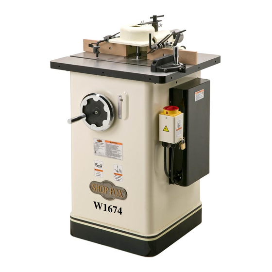
- Page 10 Two-Piece Independently Adjustable Safety Guard Adjustable Fence Dust Port Workpiece Hold-Down Miter Gauge Spindle Height Spindle Switch Handwheel Motor Cover Spindle Height Scale 1 Model W1674 controls and features. For Your Own Safety Read Instruction Manual Before Operating Shaper Wear eye protection. Be sure keyed washer is directly under spindle nut and spindle nut is tight.
- Page 11 Phone #: (360) 734-3482 • Online Tech Support: tech-support@shopfox.biz • Web: www.shopfox.biz Type ..................TEFC Capacitor Start Induction Horsepower ......................... 2 HP Voltage ........................ 110/220V Prewired ........................220V Phase ........................Single Amps ........................18/9A Speed ........................3450 RPM Cycle ........................60 Hz Number Of Speeds ......................
- Page 12 Cabinet ........................Steel Fence ........................Wood Miter Gauge ....................Cast Iron and Steel Table ....................Precision-Ground Cast Iron Guard ........................Cast Iron Paint ......................Powder Coated Weight ........................270 lbs. Length ........................24 ⁄ " Width ........................27 ⁄ " Height ........................43 ⁄...
- Page 13 For Your Own Safety, Read Manual Before Operating Machine Read and understand this Always wear hearing owner’s manual BEFORE using machine. protection when operating or observing Untrained users can be seriously hurt. loud machinery. Extended exposure to this noise without hearing protection can cause Always wear ANSI-approved permanent hearing loss.
- Page 14 Untrained operators Serious injury or can be seriously hurt by machinery. Only accidental contact with cutting tool may allow trained or properly supervised people occur if machine is tipped. Machine may be to use machine. When machine is not being damaged.
- Page 15 When setting up cuts, take every possible step to When shaping contoured work and using a reduce operator exposure to the cutter. These rub collar, NEVER start shaping at a corner. steps include but are not limited to: Keeping See the rub collar section in the manual. The the unused portion of the cutter below danger of kickback is increased when the the table, using the smallest table insert...
- Page 16 This machine must be connected to the correct size and type of power supply circuit, or fire or electrical damage may occur. Read through this section to determine if an adequate power supply circuit is available for this machine. If a correct circuit is not available, you must have a qualified electrician install one before you can operate the machine.
- Page 17 In the event of certain types of malfunctions or breakdowns, grounding provides a path of least resistance for electric current to travel— in order to reduce the risk of electric shock. Improper connection of the equipment-grounding wire will increase the risk of electric shock. The wire with green GROUNDED 220V 6-15 RECEPTACLE...
-
Page 18: Shaper Unit
This machine has been carefully packaged for safe transportation. If you notice the machine has been damaged during shipping, please contact your authorized Shop Fox dealer immediately. The following is a description of the main components shipped with the Model W1674. Lay the components out to inventory them. - Page 19 Box 3 Inventory (Figure 5) M. Spindle Washers: Guard Support........1 — Spindle Washers ⁄ " ......2 G. Guard Holding Bracket......1 — Spindle Washers ⁄ " ......2 H. T-Lock Handle (Safety Guard) ....1 N. Starting Pins ........3 O.
- Page 20 The table and other unpainted parts of your This machine distributes a shaper are coated with a waxy grease that heavy load in a small footprint. Some protects them from corrosion during shipment. residential floors may require additional bracing to support both machine and Clean this grease off with a solvent cleaner or citrus-based degreaser.
- Page 21 This machine and its components are very heavy. Use safe lifting and Anchor Stud methods, and get lifting help or use power lifting equipment such as a forklift to move the heavy items. Tools Needed Wrench 12mm ...........1 Lag Screw and Anchor Hex Wrench 5mm ..........1 Phillips Screwdriver #2 .........1 Hex Wrench 5mm, 8mm ........
- Page 22 1. Thread the handle into the hole provided on the handwheel, then fully tighten it (see Figure 10). 2. Align the set screw in the handwheel hub with the shaft flat, then slide the handwheel onto the shaft and tighten the set screw. 10 Spindle height handwheel installed.
- Page 23 2. Turn the fence assembly upside down to expose the fence ram inside the housing, as shown in Figure 14. Cap Screw 3. Remove the cap screw from the end of the fence Fence Ram ram, slide the ram out until the mounting hole in the fence assembly and the ram are aligned, then install the cap screw in the location shown in Figure 14.
- Page 24 Safety Guard T-Lock Handle The safety guard protects the operator from the spinning cutter. It adjusts with the T-lock handle. Note: To install the safety guard, do these steps: Guard Mounting Bar (Short) 1. Thread and hand-tighten the guard support into the Guard threaded hole on top of the fence assembly (see Support...
- Page 25 Complete this process once you have familiarized yourself with all instructions in this manual. To test run the shaper, do these steps: 1. Read the entire instruction manual first! 2. Make sure all tools and foreign objects have been removed from the machine. 3.
- Page 26 This machine will perform many types of operations that are beyond the scope of this manual. Many of these operations can be dangerous or deadly if performed incorrectly. The instructions in this section are written with the understanding that the operator has the necessary knowledge and skills to operate this machine.
-
Page 27: Fwd/Rev Switch
Refer Figures 20–21 and read the following descriptions below to become familiar with the basic controls of your shaper. • Spindle Switch: Starts spindle rotation, reverses rotation direction, and turns the motor • Spindle Height Lock: When tightened, secures the height position of the spindle. - Page 28 This overview explains the basic process that happens during an operation with this machine. Follow these rules when choosing and cutting Familiarize yourself with this process to better stock: understand the remaining parts of the Operation section. • Workpiece Material: Your shaper and cutters are designed to cut wood and wood products To complete a typical operation, the operator ONLY! DO NOT attempt to cut man-made...
- Page 29 Most cutters are designed to rotate counterclockwise and mill the stock from underneath the workpiece, which provides a safety barrier between the spinning cutter and ALWAYS check the direction of the cutter the operator. In this case, the workpiece is fed past the rotation before beginning operation and cutter from right to left—against the cutter rotation (see ALWAYS feed the stock into the cutter...
- Page 30 If the workpiece should rise up when it is against the cutter, kickback could occur. To reduce the chance of kickback and serious personal injury, always properly secure the workpiece with the hold-down devices during operation. The hold-downs included with your shaper are used to hold the workpiece flat on the table and snug against the fence as it passes the cutter.
- Page 31 Your shaper features a three-way adjustable fence Keep the fence opening around the assembly—the entire fence assembly moves in-or-out, both cutter as small as possible without fence mounts adjust independently in-or-out, and the interfering with the cutter rotation. This fence boards independently adjust side-to-side. configuration provides the best support for the workpiece and reduces operator exposure to the spinning cutter during...
- Page 32 The cutter speeds for the Model W1674 are 7000 and 10,000 RPM. Cutting Edge Since the cutter is mounted on the spindle, the terms Moves Much "spindle speed" and "cutter speed" are often used Faster interchangeably. Use the following rules when selecting the speed for your operation: •...
- Page 33 Your shaper has an aluminum table insert with a 1 ⁄ " Aluminum centerbore, and a larger cast iron insert ring with a 3-1/8" Insert centerbore. When removed, the aluminum insert leaves ⁄ " table opening and the insert ring leaves a 5" table opening (see Figure 34).
- Page 34 4. Reach into the cabinet from the rear and thread the drawbar nut onto the drawbar with the tapered side Drawbar Nut of the nut facing up, as shown in Figure 37. (Tapered Side Up) 37 Threading the drawbar nut with the tapered side facing up.
- Page 35 A large variety of shaper cutters are available feed direction. In this configuration, the through your local Woodstock International Inc. workpiece provides a safety barrier between Dealer. the cutter and the operator.
- Page 36 Tools Needed Spindle Wrench Set ..........1 To install a cutter, do these steps: Spacer 1. DISCONNECT SHAPER FROM POWER! Note: 2. Remove the two spindle nuts from the spindle. 3. Place the required spindle spacers on the insert, as 39 Installing a spindle spacer. shown in Figure 39.
- Page 37 6. Thread one spindle nut tightly onto the spindle to secure the components, then thread the second spindle nut against the first to act as a lock nut (see Figures 42–43). To avoid the risk of severe injury or amputation, Spindle ALWAYS properly install the safety guard onto the Nuts...
- Page 38 The safety guard on the Model W1674 is installed with or without the fence assembly, and accepts an adjustable front guard for additional protection from accidental cutter contact during operation. When the safety guard is mounted on the fence assembly, adjust its position by moving the entire fence assembly To avoid the risk of severe injury or (refer to Fence Adjustment on Page 24 for detailed...
- Page 39 Flat of Tools Needed Shaft Wrench or Socket 14mm ........1 Hex Wrench 4mm ..........1 To install the safety guard independent of the fence Shaft assembly, do these steps: Holder 1. DISCONNECT SHAPER FROM POWER! Set Screw 2. Remove the fence assembly from the table. 3.
- Page 40 The fence boards are a two-piece, independently adjustable system. When removing material from the edge of your workpiece, the outfeed fence can be adjusted Because the fence may not always be to provide support for the workpiece as it passes by the perfectly parallel to the table miter cutter for either full or partial edge cutting.
- Page 41 1. DISCONNECT SHAPER FROM POWER! Outfeed Infeed Fence Fence 2. Adjust the infeed fence to the desired depth of cut, then lock it in place. 3. Use a straightedge to adjust the outfeed fence even with the infeed fence, then lock it in place. Direction of Feed 4.
- Page 42 Your shaper can perform rabbet cuts by using a straight cutter and properly adjusting the spindle height and the fences to produce the desired L-shape cut in the workpiece (see Figure 50). To make a rabbet cut, do these steps: 1.
- Page 43 Feeding small stock through a shaper is always dangerous. If you must shape small stock, use a zero-clearance fence. This will provide greater protection for the operator, ALWAYS use hold-downs or featherboards better workpiece support, and reduced tearout on narrow and push sticks when shaping small or or fragile stock.
- Page 44 Recommended! There are two types of rub collars—solid and ball bearing. We recommend using ball bearing collars for smooth operation. Woodstock carries an extensive line of rub Collar collars that are available through your local Woodstock International Inc. dealer.
- Page 45 Swing Starting Pin Collar Workpiece Feed Direction Freehand or irregular shaping greatly increases the chance that the operator may lose control of the 55 Using a starting pin for workpiece, which could result in serious personal irregular shaping. injury. Therefore, a starting pin or support MUST be used to start an irregular shaping operation.
- Page 46 With some irregular shaping operations, the locations of the starting pin holes are not in the best positions. When this is the case, clamp a wood scrap to the shaper table, as shown in Figure 58, then use the wood as the starting support.
- Page 47 Dealer. If you do not have a dealer in your area, these products are also available through online dealers. Please call or e-mail Woodstock International Inc. Customer Service to get a current listing of dealers at: 1-800-840-8420 or at sales@woodstockint.com.
- Page 48 For optimum performance from your machine, follow this maintenance schedule and refer to any specific instructions given in this section. Note: Daily: • Clean and protect the top surfaces. • Check/tighten loose mounting bolts. • Check/replace damaged or worn cutters. •...
- Page 49 Since all bearings are sealed and permanently lubricated, simply leave them alone until they need to be replaced. Leadscrew Do not lubricate them. However, the spindle slide and leadscrew do need lubrication. To lubricate the spindle slide and leadscrew, do these steps: 1.
- Page 50 The V-belt transfers power from the motor to the spindle. If the V-belt does not have the proper tension or is damaged in any way, the shaper will not operate optimally and unnecessary wear on the moving parts will occur. Regularly check the V-belt tension and replace it when necessary.
- Page 51 If you require additional machine service not included in this section, please contact Woodstock International Technical Support at (360) 734-3482 or send e-mail to: The aluminum table insert is held in place by a cast iron insert ring, which should be adjusted level with the table top (see Figure 63).
- Page 52 For safe and accurate shaping, the fence boards must be parallel with one another so that they properly support the workpiece through the entire cutting operation. Tools Needed Phillips Screwdriver #2 .........1 Precision Straightedge 24" ........1 Shims ..........As Needed To check and align the fence boards parallel with each other, do these steps: 1.
- Page 53 Tools Needed Precision Straightedge .........1 Phillips Screwdriver #2 .........1 Wrench or Socket 12mm ........1 Wrench or Socket 14mm ........1 Mounting Bolts To make the pulleys parallel, do these steps: 1. DISCONNECT SHAPER FROM POWER! 2. Remove the motor cover from the cabinet, then loosen the two motor mounting hex bolts that are behind the motor mount (see Figure 67).
- Page 54 The gib controls the smoothness of the slide movement, as well as, the run out or end play of the spindle. Tightening the gibs too much will make it hard to adjust the height of the spindle and cause excessive wear on the slide.
- Page 55 These pages are current at the time of printing. However, in the spirit of improvement, we may make changes to the electrical systems of future machines. Study this diagram carefully. If you notice differences between your machine and these wiring diagrams, call Woodstock International Technical Support at (360) 734-3482.
- Page 56 wiring diagram 70 Motor wiring. 71 Spindle switch wiring. Spindle Switch FOR STOP REV 220V Single-Phase Read Page 48 Motor (Pre-Wired) STOP Before Wiring Ground 110V Motor 220V Single-Phase NEMA 6-15 Plug (As Recommended) Neutral Ground 110V NEMA 5-20 Plug (As Recommended) -49-...
- Page 57 This section covers the most common problems and corrections with this type of machine. WARNING! DO NOT make any adjustments until power is disconnected and moving parts have come to a complete stop! 1. Ensure power supply is ON/has correct voltage. Machine does not start or a 1.
- Page 58 Spindle does not raise or 1. Spindle slide or leadscrew is clogged 1. Clean the spindle slide and leadscrew, then lower easily. with sawdust. lubricate them (refer to Page 42 Workpiece is burned when 1. Dull cutter. 1. Replace cutter or have it professionally sharpened. cut.
- Page 59 19-1 32V2 35V2 36V2 -52-...
-
Page 60: Fence Assembly
REF PART # DESCRIPTION REF PART # DESCRIPTION X1674001 STAND 32V2 X1674032V2 LOCKING F/R SWITCH V2.09.10 2V2 X1674002V2 MOTOR COVER V2.09.05 X1674033 SWITCH BOX COVER XPS06 PHLP HD SCR 10-24 X 3/8 X1674034 SWITCH MOUNT BRACKET XPB21 HEX BOLT 3/8-16 X 3/4 35V2 X1674035V2 MOTOR CORD 14AWG 5C 86CM XPLW04 LOCK WASHER 3/8... - Page 61 145-2 145-5 145-4 145-1 145-3 123A -54-...
- Page 62 PART # DESCRIPTION PART # DESCRIPTION X1674101 HANDLE XPB11 HEX BOLT 5/16-18 X 1-1/2 X1674103 HANDWHEEL XPB19 HEX BOLT 1/4-20 X 1/2 XPSS02 SET SCREW 5/16-18 X 3/8 XPW06 FLAT WASHER 1/4 XPSS11 SET SCREW 1/4-20 X 1/4 X1674133 BRACKET X1674106 COLLAR X1674134...
-
Page 63: Spindle Wrench Set
201D 201C 201A 201B 233B 233A PART # DESCRIPTION PART # DESCRIPTION 201A X1674201A SPINDLE 1/2" X1674220 DRAWBAR NUT 5/16-24 201B X1674201B SPINDLE 3/4" W1159 SPACER 1/2" x 1" x 1/4" 201C X1674201C SPINDLE NUT SET 1/2" W1160 SPACER 1/2" x 1" x 3/8" 201D X1674201D SPINDLE NUT SET 3/4"... -
Page 64: Safety Guard
406-1 415V2 416V2 PART # DESCRIPTION PART # DESCRIPTION XPSS02 SET SCREW 5/16-18 X 3/8 XPN05 HEX NUT 1/4-20 X1674402 SHAFT MOUNT X1674414 EXTENSION BAR XPLW04 LOCK WASHER 3/8 415V2 X1674415V2 OVERHEAD SAFETY GUARD V2.09.10 XPB18 HEX BOLT 3/8-16 X 1 416V2 XPFH02 FLAT HD SCR 10-24 X 1 X1674405... - Page 65 PART # DESCRIPTION PART # DESCRIPTION X1674501 HOLD-DOWN BAR X1674503 HOLD-DOWN BRACKET X1674502 HOLD-DOWN XPSS03 SET SCREW 1/4-20 X 3/8 603-1 PART # DESCRIPTION PART # DESCRIPTION X1674601 HANDLE XPSS32 SET SCREW 10-24 X 3/4 XPW07 FLAT WASHER 5/16 XPSS29 SET SCREW 10-24 X 1/4 X1674603 MITER GAUGE BODY...
- Page 67 FOLD ALONG DOTTED LINE Place Stamp Here FOLD ALONG DOTTED LINE TAPE ALONG EDGES--PLEASE DO NOT STAPLE...
Need help?
Do you have a question about the Shop Fox W1674 and is the answer not in the manual?
Questions and answers
I bought aw1674 shopfox shaper and the 220 v input wires were removed. I need to know what terminals to connect the 220 volt wires to.