turck Ri-QR24 Operating Instructions Manual
Contactless encoders with canopen interface
Hide thumbs
Also See for Ri-QR24:
- Instructions for use manual (29 pages) ,
- Nstructions for use (40 pages) ,
- Instructions for use manual (40 pages)

Related Manuals for turck Ri-QR24


Summary of Contents for turck Ri-QR24
- Page 1 OPERATING INSTRUCTIONS CONTACTLESS QR24 ENCODERS WITH CANOPEN INTERFACE Sense it! Connect it! Bus it! Solve it!
- Page 2 QR24 Encoder with CANopen Interface Hans Turck GmbH & Co. KG • Tel. +49 208 4952-0 • Fax +49 208 4952-264...
-
Page 3: Table Of Contents
Contactless Ri-QR24 encoders – with CANopen interface About this manual ........................4 Target groups ..........................4 Explanation of symbols ......................4 Other documents ........................4 Feedback on this manual ......................4 Notes on the product ......................... 5 Product identification (type key) ..................... 5 Scope of delivery ........................ -
Page 4: About This Manual
We make every effort to ensure that these instructions are as informative and as clear as possible. If you have any suggestions for improv- ing the design or if some information is missing in the document, please send your suggestions to techdoc@turck.com. -
Page 5: Notes On The Product
Set M2-QR24 P3 P3-Ri-QR24/12 mm (M1-QR24 + SP1-QR24) P4 P4-Ri-QR24/10 mm Set M3-QR24 P5 P5-Ri-QR24/6 mm (M1-QR24 + P6 P6-Ri-QR24 / 3/8" SP2-QR24) P7 P7-Ri-QR24 / 1/4" Set M4-QR24 P8 P8-Ri-QR24 / - (M1-QR24 + SP3-QR24) Measuring range Housing style 360 360°... -
Page 6: Scope Of Delivery
The product is designed according to the state of the art technology. Residual hazards, however, still exist. Observe the following warn- ings and safety regulations in order to prevent danger to persons and property. Turck accepts no liability for damage caused by failure to observe these warnings and safety instructions. -
Page 7: Product Description
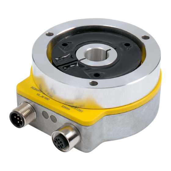
– Robust, easy to assemble plastic housing – Suitable for industrial applications – Temperature range: -25…+85°C – Housing protection type: IP68/IP69K 4.1 Device view ø 65 ø 78 ø 22 ø 4.3 42.3 M12 x 1 Fig. 1: Device view more@turck.com • www.turck.com • 2018/01... -
Page 8: Function Principles
The PWR LED will respond at as little as 5 V, and is therefore not an indicator for having reached the operating voltage of 10…30 V. Hans Turck GmbH & Co. KG • Tel. +49 208 4952-0 • Fax +49 208 4952-264... - Page 9 Red – Three short flashes SYNC error The SYNC message was not received within the preconfigured cycle time (see also ob- ject 0x1006) Red – continuously lit Bus deactivated The CAN controller was deactivated by the more@turck.com • www.turck.com • 2018/01...
-
Page 10: Connection Assignments
*) UL marking requires an approved power supply with energy limitation (UL 61010-1) or with Class 2 according to National Electric Code (USA) / Canadian Electric Code. 4.6 Terminating resistor An integrated terminating resistor can be activated as needed. (See object 0x2102). Hans Turck GmbH & Co. KG • Tel. +49 208 4952-0 • Fax +49 208 4952-264... -
Page 11: Assembly
6 The protective aluminium unit and the positioning element). Mount the encoder depending on applica- over the positioning element, and affix shield plate SP1-QR24 can optionally be with three screws, to create a closed, and added. tion requirement. protected unit. more@turck.com • www.turck.com • 2018/01... -
Page 12: Configuration
Bit 10 =1: Operating range 1 underrun Bit 11 =1: Operating range 2 out of range Bit 12 =1: Operating range 2 underrun Bit 13 =1: Operating range 2 underrun Hans Turck GmbH & Co. KG • Tel. +49 208 4952-0 • Fax +49 208 4952-264... - Page 13 "HW-12718801 -" in ASCII code Hardware version (127xxxxx) incl. change index (-, A, B…) 6.1.7 Object 100Ah: Manufacturer software version Contains the manufacturer's software version number. 100Ah Manufacturer software version Vis string Data content: e.g. "SW-1.0.0.1" in ASCII code more@turck.com • www.turck.com • 2018/01...
- Page 14 The default values become valid only after a "NMT reset“. After a "NMT reset" the command "Save parameter" (see object 1010h) must also be executed if the default values are to be applied to EEPROM as well. l o a d = 0x64616F6C Hans Turck GmbH & Co. KG • Tel. +49 208 4952-0 • Fax +49 208 4952-264...
- Page 15 0000h ("Error reset" or "No error") will be generated and sent to the bus. Emergency messages for Turck CANopen sensors: Code 0000h = No error An "Emergency clear" message (code 0000h) will be transmitted during startup and after the "Boot up" message.
- Page 16 SW revision number (e.g. 1.0.0.1), see table "3-Point notation" Example: Version 1.0.0.1 = 10 = 0Ah_01h = 0A01h Sub-index 4h: delivers the 8-digit serial number of the encoders Hans Turck GmbH & Co. KG • Tel. +49 208 4952-0 • Fax +49 208 4952-264...
- Page 17 NV RAM / EEPROM error ■ System monitoring error Value range (8 bit unsigned): 0 = sensor changes to pre-operational mode 1 = sensor does not change mode 2 = sensor changes to stopped mode more@turck.com • www.turck.com • 2018/01...
- Page 18 250 kBit/s 1 ms 125 kBit/s 0,97 2 ms 50 kBit/s 0,39 3 ms 20 kBit/s 0,15 7 ms 10 kBit/s 0,07 15 ms Hans Turck GmbH & Co. KG • Tel. +49 208 4952-0 • Fax +49 208 4952-264...
- Page 19 Stopped: Data 04h NOTE The number of possible messages is limited by the bus speed. Minimum times for event timer are valid for the operation with one PDO. This is also valid for SNC times. more@turck.com • www.turck.com • 2018/01...
- Page 20 Combination with inhibit timer (inhibit time) possible 255: Asynchronous = 0xFFh, value is updated and sent after completion of cycle time (device timer ≠ 0) Hans Turck GmbH & Co. KG • Tel. +49 208 4952-0 • Fax +49 208 4952-264...
-
Page 21: Variables Pdo Mapping
Mapping object 3 No entry, as 64 bits assigned Mapping object 3 Alarms 1A00h,0x03 1A01h,0x03 16 bit Mapping object 4 No entry, as 64 bits assigned Mapping object 4 No entry, as 64 bits assigned 1A00h,0x04 1A01h,0x04 more@turck.com • www.turck.com • 2018/01... - Page 22 0x1010, 0x01: Save parameters, data: 0x6576617 (PWR on reset required) Sub-index 2h: 2_mapped_object (default: no entry) Sub-index 3h: 3_mapped_object (default: no entry) Sub-index 4h: 4_mapped_object (default: no entry) Hans Turck GmbH & Co. KG • Tel. +49 208 4952-0 • Fax +49 208 4952-264...
- Page 23 Sub-index 0h: Number of supported sub-indices. Read only Value range: 1...4 Sub-index 1h: 1_mapped_object (default: 0x60040020, position value) Sub-index 2h: 2_mapped_object (default: no entry) Sub-index 3h: 3_mapped_object (default: no entry) Sub-index 4h: 4_mapped_object (default: no entry) more@turck.com • www.turck.com • 2018/01...
- Page 24 B ) Current metering values are stored in object 6030h sub-index 01h only. C ) The mapping is stored in object 1A02h sub-index 01h. Hans Turck GmbH & Co. KG • Tel. +49 208 4952-0 • Fax +49 208 4952-264...
- Page 25 The default assignment of the process data objects (default mapping) will generally satisfy requirements. For special use cases, the assign- ment can be changed: Many Turck CANopen devices support variable mapping, which allows the free assignment of application objects (input and output data) to PDOs. This will require a configuration of the mapping tables: Only the following procedure is permissible as of CANopen version 4, which must be complied with to the letter: 0x1800ff, sub-index 1, COB ID, set bit 31 to "1"...
-
Page 26: Objects 2000H - 2Fffh (Manufacturer Specifications)
A new node number is applied only after the next boot-up (Reset/Power ON) of the encoder. All other settings in the object table remain unchanged. Hans Turck GmbH & Co. KG • Tel. +49 208 4952-0 • Fax +49 208 4952-264... - Page 27 A low pass filter (moving average) is a first order type. The dynamic digital filter is status and speed-dependent. The filter constant can be set in object 2106h, sub-index 0x02. A switchover to a high threshold frequency occurs (low group delay), when the position- ing element is moved. more@turck.com • www.turck.com • 2018/01...
- Page 28 - Not available in the EDS file. NOTE A password is necessary to change the object. Service-pass code object 0x2900, 0x01 (Unsigned32). The password is 12345 (dec) resp. 0x3039. Hans Turck GmbH & Co. KG • Tel. +49 208 4952-0 • Fax +49 208 4952-264...
-
Page 29: Objects 6000H - 6Fffh (Default Device Parameters)
1 … max. physical resolution (full range) RI360P0-QR24M0-CNX4-2H1150: 327680 = full range Default settings: 36000 NOTE The max. physical resolution is a factory setting in object 6501h (read only). In object 6000h bit 2: Set scaling function to enable (1). more@turck.com • www.turck.com • 2018/01... - Page 30 The max. physical resolution is a factory setting in object 6501h (read only). In object 6000h bit 2: Set scaling function to enable (1). Hans Turck GmbH & Co. KG • Tel. +49 208 4952-0 • Fax +49 208 4952-264...
- Page 31 Offset value = preset value - position measuring value 6.4.5 Object 6004h: Position value The encoder outputs the current position value (poss. after calculation with scaling factor). 6004h Position value Unsigned32 Data: Value range: 0... max. physical resolution Default: actual position more@turck.com • www.turck.com • 2018/01...
- Page 32 Value range: 0…FFFFh (65535 ) provides the cycle time in milliseconds. Default value: 100 NOTE No measuring value output occurs if cycle time = 0. Hans Turck GmbH & Co. KG • Tel. +49 208 4952-0 • Fax +49 208 4952-264...
- Page 33 These area markers can also be used as software end switches. 6401h/02h Working area limits H/L Integer32 Object 6401h: Working area LOW limit 2 values Object 6402h: Working area HIGH limit 2 values Value ranges: Ri360P0-QR24M0-CNX4-2H1150: 0… 327680 dec. (full range) more@turck.com • www.turck.com • 2018/01...
- Page 34 (high limit 2) 6.4.11 Object 6500h: Operating status read only This is where the basic settings can be read from object 6000h. 6500h Operating status Unsigned16 Hans Turck GmbH & Co. KG • Tel. +49 208 4952-0 • Fax +49 208 4952-264...
- Page 35 Bit 15: 1 = no RLC coupling, no position metering possible In the event of an alarm, an emergency message (ID = 80h + node number) with error code 1000h (generic error) is sent simultaneously. more@turck.com • www.turck.com • 2018/01...
- Page 36 Bit 0…5: free Bit 6: 1= Warning message "Overspeed" is supported. Bit 7…14: free Bit 15: 1= Warning message "RLC coupling weak" is supported. Hans Turck GmbH & Co. KG • Tel. +49 208 4952-0 • Fax +49 208 4952-264...
- Page 37 Byte 1 Byte 0 ... 2 ... 2 ... 2 ... 2 Example: CiA DS406 version: 3.2 = 3 = 03h_02h Software version: 1.0.0.1= 10 = 0Ah_01h Byte 3 Byte 2 Byte 1 Byte 0 more@turck.com • www.turck.com • 2018/01...
-
Page 38: Lss Services Ds 305 V2.0
Revision number (major and minor revision as numerical number) ■ Serial number (numerical number) ■ LSS master CAN ID 2021 ■ LSS slave CAN ID 2020 Hans Turck GmbH & Co. KG • Tel. +49 208 4952-0 • Fax +49 208 4952-264... -
Page 39: Network Management
Prepared or stopped: In this state, the node is no longer enabled, i.e. no SDO or PDO communication is possible. The node can be cycled to the status "Operational" or "Pre-operational" via NMT commands. NOTE The Encoder-LED might be different from the selected node-condition. more@turck.com • www.turck.com • 2018/01... - Page 40 M4-QR24 M1-QR24 + the positioning element ø 28 SP3-QR24 ø 24 Shield plate Ø 52 mm, aluminium 120° ø 3.2 ø 52 ø 42 Hans Turck GmbH & Co. KG • Tel. +49 208 4952-0 • Fax +49 208 4952-264...
- Page 41 ø 52 ø 42 P7-Ri-QR24 Positioning element for connec- ø 1/4“ tion on shafts with Ø 1/4" ø 3.2 ø 52 ø 42 P8-Ri-QR24 Positioning element with blind plug ø 3.2 ø 52 ø 42 more@turck.com • www.turck.com • 2018/01...
- Page 42 LED green, flashing green Error indication LED red, flashing red Miscellaneous Included in the scope of delivery Assembly aid MT-QR24 VZ 3 screw plug Hans Turck GmbH & Co. KG • Tel. +49 208 4952-0 • Fax +49 208 4952-264...
-
Page 43: Service
Please note that we can only accept the return of devices accompanied by a decontamination declaration, should it become necessary to return a device. The declaration form is available for download at http://www.turck.de/static/media/downloads/Dekontamination_de.pdf, must be filled out completely, and must be attached to the exterior of the packaging in a transport-safe and weather-proof sleeve. - Page 44 Hans Turck GmbH & Co. KG Witzlebenstr. 7 45472 Mülheim an der Ruhr Germany Your Tel. +49 (0) 208 4952-0 Automation Partner Fax +49 (0) 208 4952-264 Email more@turck.com Internet www.turck.com Worldwide! D102186 2018/01 *D102186* Errors and changes reserved...
Need help?
Do you have a question about the Ri-QR24 and is the answer not in the manual?
Questions and answers