Table of Contents
Advertisement
Quick Links
Instructions
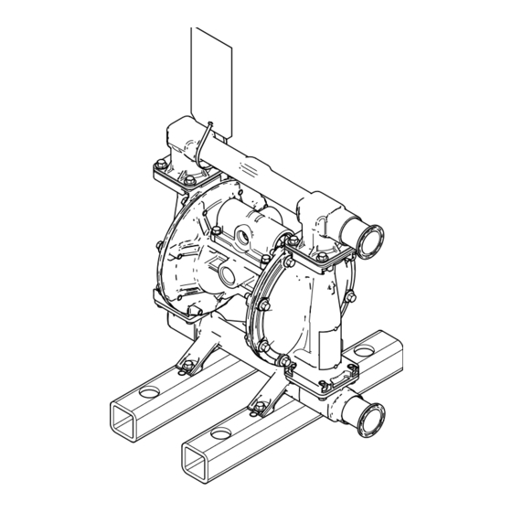
SaniForce
Pumps, BV-Series
Air-operated double-diaphragm (AODD) pumps for sanitary fluid transfer applications. For
professional use only.
1050, 1590, and 2150 Models
See page 2 for model information, including approvals.
120 psi (0.8 MPa, 8 bar) Maximum Fluid Working
Pressure
120 psi (0.8 MPa, 8 bar) Maximum Air Input Pressure
Important Safety Instructions
Read all warnings and instructions in this
manual before using the equipment.
Save these instructions.
Diaphragm
®
1050 Pump
2150 Pump
3A8983A
EN
1590 Pump
Advertisement
Table of Contents

Related Manuals for Graco SaniForce BV Series


Summary of Contents for Graco SaniForce BV Series
- Page 1 Instructions SaniForce Diaphragm ® Pumps, BV-Series 3A8983A Air-operated double-diaphragm (AODD) pumps for sanitary fluid transfer applications. For professional use only. 1050, 1590, and 2150 Models See page 2 for model information, including approvals. 1050 Pump 120 psi (0.8 MPa, 8 bar) Maximum Fluid Working Pressure 1590 Pump 120 psi (0.8 MPa, 8 bar) Maximum Air Input Pressure...
-
Page 2: Table Of Contents
Troubleshooting ......16 Graco Information......50 Repair . -
Page 3: Warnings
Warnings Warnings The following warnings are for the setup, use, grounding, maintenance, and repair of this equipment. The exclamation point symbol alerts you to a general warning and the hazard symbols refer to procedure-specific risks. When these symbols appear in the body of this manual or on warning labels, refer back to these Warnings. Product-specific hazard symbols and warnings not covered in this section may appear throughout the body of this manual where applicable. - Page 4 Warnings WARNING PRESSURIZED EQUIPMENT HAZARD Fluid from the equipment, leaks, or ruptured components can splash in the eyes or on skin and cause serious injury. • Follow the Pressure Relief Procedure when you stop spraying/dispensing and before cleaning, checking, or servicing equipment. •...
-
Page 5: Configuration Matrix
Configuration Matrix Configuration Matrix Record the model part number and configuration sequence found on your equipment identification plate (ID) to assist you when ordering replacement parts. Model Part Number: _______________________________________________ Configuration Sequence: _______________________________________________ Sample Configuration Sequence: 1050BVPA01AS16SSCWSPEP 1050 A01A Pump Wetted Drive Center... -
Page 6: Typical Installation
Typical Installation Typical Installation General Information Always use Genuine Graco Parts and accessories. Be sure all accessories are adequately sized and A typical installations is shown in F . 1. The figure is pressure-rated to meet the requirements of the system. -
Page 7: Installation
Installation Installation Before First Use • Pump: Connect a ground wire and clamp to the grounding screw (W). To order a ground wire and clamp, order part number 222011. Tighten Fasteners 1. Loosen the grounding screw (W). Before using the equipment for the first time, check and torque all fasteners. -
Page 8: Mount The Pump
Installation Mount the Pump Ventilate Air Exhaust The equipment is heavy (see Technical Be sure the system is properly ventilated for your type of installation. Exhaust must be vented to a safe Specifications for specific weights). If the equipment place, away from people, animals, food handling must be moved, follow the Pressure Relief areas, and all sources of ignition when pumping Procedure, page 12, and have two people lift the... -
Page 9: Install Accessories
Installation Install Accessories Install Fluid Supply and Outlet Lines Install the following accessories in the order shown in • Fluid drain valve (J): Required in your system, . 1, using adapters as necessary. relieves fluid pressure in the fluid line. •... -
Page 10: Tips To Reduce Cavitation
Installation Tips to Reduce Cavitation Orient Fluid Inlet and Outlet Ports NOTICE The inlet and outlet fluid port can be rotated. To change Frequent or excessive cavitation can cause serious the fluid port orientation of the manifold (102, 103): damage, including pitting and early wear of wetted parts, and may result in reduced efficiency of the 1. -
Page 11: Fluid Pressure Relief Valve
Installation Fluid Pressure Relief Valve KEY: Fluid inlet port Fluid outlet port Fluid pressure relief valve Install valve between fluid inlet and outlet ports. Some systems may require installation of a pressure Connect fluid inlet line here. relief valve (V) at the pump outlet to prevent overpressurization and rupture of the pump or fluid Connect fluid outlet line here. -
Page 12: Operation
Operation Operation Pressure Relief Procedure Before Each Use Follow the Pressure Relief Procedure Tighten Fasteners whenever you see this symbol. Check and tighten all fasteners before operating the equipment. Re-torque as needed. Follow Torque Fasteners, page 36. NOTICE This equipment stays pressurized until pressure is To avoid pump damage, do not over-torque the manually relieved. -
Page 13: Start And Adjust The Equipment
Operation Start and Adjust the Equipment 7. If the fluid outlet line (L) has a dispensing device, hold it open while continuing with the following 1. Confirm that the equipment is properly grounded. step. See Grounding, page 7. 8. To prime the pump, slowly increase air pressure 2. -
Page 14: Maintenance
Maintenance Maintenance Establish a Preventive Lubricate the Equipment Maintenance Schedule The equipment is lubricated at the factory. It is designed to require no further lubrication for the life of the equipment. There is no need to add an inline NOTICE lubricator under normal operating conditions. -
Page 15: Flush The Equipment
Recycling and Disposal Flush the Equipment Store the Equipment Always relieve the pressure and flush the equipment before storing the equipment for any length of time. To avoid fire and explosion, always ground 1. Follow Pressure Relief Procedure, page 12. equipment and waste container. -
Page 16: Troubleshooting
Troubleshooting Troubleshooting 1. Follow Pressure Relief Procedure, page 12, before checking or repairing the equipment. 2. Check all possible problems and causes before disassembling equipment. Problem Cause Solution Pump cycles at stall or fails to hold Worn check valve balls (301), seats Replace. - Page 17 Troubleshooting Problem Cause Solution Pump leaks air externally. Loose, worn, or damaged air Tighten fasteners on air section. section parts. See pages 22–26. Repair or replace parts. See pages 22–26. Pump leaks fluid externally from ball Loose manifolds (102, 103), Tighten manifold fasteners (106) or check valves.
-
Page 18: Repair
Repair Repair Repair kits available (purchase separately). Use all parts in the kits for best results. See Parts, starting on page 28. Repair the Check Valve NOTE: Ensure that the check valves and seating areas are clean. Tools Required: 2. Align manifolds (102, 103) with fluid covers (101). •... -
Page 19: Repair The Diaphragm
Repair Repair the Diaphragm Install the Diaphragms Tools Required: • Torque wrench 1. Assemble the diaphragm plates (104, 105), packing • 13 mm socket wrench o-ring (108), and diaphragm (401) onto the • 15 mm socket wrench diaphragm shaft fastener (107). See F . - Page 20 Repair Apply medium-strength (blue) thread locker to the threads and torque. Torque to 20–25 in-lb (3.5–4.4 N•m) Torque. See Torque Fasteners, page 36. 106, 106b . 7: Diaphragm Section, 1590 model shown 3A8983A...
- Page 21 Repair 03981A 03982A Cutaway View, with diaphragms Cutaway View, diaphragms removed . 8: Diaphragm Section, Cutaway Views Lips face out of housing (1). Rounded side faces diaphragm (401). AIR SIDE must face center housing (1). Grease. Apply medium-strength (blue) thread locker. Torque to 20–25 ft-lb (27–34 N•m) at 100 rpm maximum. Recessed side faces diaphragm (401).
-
Page 22: Repair The Air Valve For 1050 Pumps
Repair Repair the Air Valve for 1050 Install the Air Valve for 1050 Pumps Pumps 1. Grease the detent cam (43). 2. Install the detent cam (43) into housing (40). Tools Required: • Torque wrench 3. Grease the u-cups (47). •... - Page 23 Repair 14. Align the magnet (51b) in the base (51) with the air inlet (40b) of the housing (40) and install the cup (52) assembly. ti19675a . 11: Base assembly 15. Grease the cup (52) side and install the valve plate (44).
-
Page 24: Repair The Air Valve For 1590 And 2150 Pumps
Repair Repair the Air Valve for 1590 and 11. Inspect the bearings (12, 15). If damaged, follow Replace the Bearing and Air Gasket, page 26. 2150 Pumps NOTE: Do not remove undamaged bearings. Tools Required: 12. Clean and inspect for wear or damage. Replace as •... - Page 25 Repair Install the Air Valve for 1590 and 2150 Pumps 1. If bearings (12, 15) were removed, install new bearings. See Replace the Bearing and Air Gasket, page 26. 2. Install the valve plate seal (9) into the groove at the bottom of the valve cavity.
-
Page 26: Replace The Bearing And Air Gasket
Repair Replace the Bearing and Air Gasket Install the Bearing and Air Gasket Tools Required: • Torque wrench 1. If removed, install the shaft u-cup packings (402). • 10 mm socket wrench Ensure the lips face out of the housing (1). •... - Page 27 Repair Insert bearings tapered end first. Press-fit bearings flush with surface of center housing (1) Apply medium-strength (blue) thread locker to the – – threads. Torque to 120 150 in-lb (14 17 N•m). . 19: Detail of Air Valve Bearings .
-
Page 28: Parts
Parts Parts Center Section and Air Section Parts for 1050 Pumps 1050 pump shown 3A8983A... - Page 29 Parts Center Section and Air Section Parts List for 1050 Pumps – – –* CAP, end Ref. Part No. Description Qty. – – –* U-CUP 18F321* HOUSING, center – – –* SCREW – – –* BEARING, shaft – – –* RETAINING RING 116343 SCREW, grounding...
-
Page 30: Center Section And Air Section Parts For 1590 And 2150 Pumps
Parts Center Section and Air Section Parts for 1590 and 2150 Pumps 1590 pump shown 3A8983A... - Page 31 Parts Center Section and Air Section Parts List for 1590 and 2150 Pumps 116343 SCREW, grounding Ref. Part No. Description Qty. 188603 GASKET, air cover 188838 HOUSING, center COVER, air 188854 COVER, air valve 189400 for 1590 pumps 116344 FASTENER 189300 for 2150 pumps –...
-
Page 32: Fluid Section Parts
Parts Fluid Section Parts 125▲ 124▲ 106, 106b 1590 pump shown 3A8983A... - Page 33 Parts Fluid Section Parts List MUFFLER 24D642 for 1050 pumps Ref. Part/Kit Description Qty. 102656 for 1590 pumps MOTOR, assembly for 2150 pumps 20A734 for 1050 pumps FASTENER 237372 for 1590 pumps – – – for 1050 pumps 237360 for 2150 pumps 115645 for 1590 pumps;...
-
Page 34: Kits And Accessories
Kits and Accessories Kits and Accessories To define material codes and reference numbers, see Configuration Matrix, page 5, and Parts, starting on page 28. Part Kits Part kits are available (purchase separately). Seat Kits Air Valve Repair Kits Includes Includes Pump Kit No. -
Page 35: Accessory Kits
Kits and Accessories Center Section Rebuild Kits Air Valve Seals Kits Includes Includes Pump Kit No. Refs. Description Qty. Pump Kit No. Refs. Description Qty. 1050 24B621 VALVE 1050 24B769 O-RING CARTRIDGES U-CUP O-RING SCREW SHAFT 1590 – – – –... -
Page 36: Torque Fasteners
Torque Fasteners Torque Fasteners Torque Instructions Torque Sequence To ensure proper sealing, torque fasteners using the Fully torque all fasteners on the fluid covers before following procedure. torquing the fasteners on the manifolds. 1. Start all fasteners a few turns. Follow Torque Instructions, page 36. - Page 37 Torque Fasteners Torque Sequence for 1590 and 2150 Pumps Fluid Covers Manifolds For 1590 and 2150 Pumps: Torque For 1590 and 2150 Pumps: Torque to 120–150 in-lb (21–26 N•m) to 190–220 in-lb (33–39 N•m) 3A8983A...
-
Page 38: Performance Charts
Performance Charts Performance Charts To find Fluid Outlet Pressure (psi/bar/MPa) at a To find Air Consumption (scfm or m /min) at a specific specific fluid flow (gpm/lpm) and operating air pressure fluid flow (gpm/lpm) and air pressure (psi/bar/MPa): (psi/bar/MPa): 1. Locate the fluid flow rate along the bottom of the 1. -
Page 39: Performance Charts For 1050 Pumps
Performance Charts Performance Charts for 1050 Pumps Test Conditions: Pump tested in water with inlet submerged. Cycle Rate (0.83. 8.3) Fluid Pressure (0.7, 7.0) (0.55, 5.5) (0.41, 4.1) Operating Air Pressure (0.28, 2.8) (0.14, 1.4) 125 psi (0.83 MPa, 8.3 bar) (19) (38) (57) -
Page 40: Performance Chart For 1590 Pumps
Performance Charts Performance Chart for 1590 Pumps Test Conditions: Pump tested in water with inlet submerged. feet (meters) (MPa, bar) INLET AIR PRESSURES (0.8, 8) (85.3) 120 psi air (0.8, 8 bar) 100 psi air (0.7, 7 bar) (73.2) 70 psi air (0.49, 4.9 bar) (0.7, 7.0) 40 psi air (0.28, 2.8 bar) (61.0) -
Page 41: Performance Chart For 2150 Pumps
Performance Charts Performance Chart for 2150 Pumps Test Conditions: Pump tested in water with inlet submerged. (4.2) (8.4, 0.84) (3.5) (7, 0.7) (7, 0.7) (2.8) (5.5, 0.55) (4.1, 0.41) (2.1) (1.4) (2.8, 0.28) (1.4, 0.14) (0.7) (lpm) (76) (152) (227) (303) (379) (454) -
Page 42: Dimensions
Dimensions Dimensions Dimensions for 1050 Pumps Dimensions for 1050 Pumps 51.48 15.93 14.94 3.13 11.81 11.37 8.13 15.00 5.50 11.00 393.19 404.60 379.47 79.50 299.97 288.80 206.50 381.00 139.70 279.40 Dimensions can vary by up to 1/4 in. (6.3 mm) depending on the diaphragm material fitted in the equipment. 3A8983A... -
Page 43: Dimensions For 1590 Pumps
Dimensions Dimensions for 1590 Pumps Dimensions for 1590 Pumps 17.63 21.76 20.50 4.19 16.31 13.50 7.50 15.00 6.00 11.00 447.80 552.70 520.70 106.43 414.27 342.90 190.50 381.00 152.40 279.40 Dimensions can vary by up to 1/4 in. (6.3 mm) depending on the diaphragm material fitted in the equipment. 3A8983A... -
Page 44: Dimensions For 2150 Pumps
Dimensions Dimensions for 2150 Pumps Dimensions for 2150 Pumps 19.60 26.27 24.75 2.50 22.25 15.17 6.25 12.50 6.50 6.00 497.80 667.26 628.65 63.50 565.15 385.32 158.75 317.50 165.10 152.40 Dimensions can vary by up to 1/4 in. (6.3 mm) depending on the diaphragm material fitted in the equipment. 3A8983A... -
Page 45: Technical Specifications
Technical Specifications Technical Specifications Technical Specifications for 1050 Pumps SaniForce Diaphragm Pumps, BV-Series, 1050 Pumps Metric Maximum fluid working pressure 120 psi 0.83 MPa, 8.27 bar Air pressure operating range* 20–120 psi 0.14–0.83 MPa, 1.38–8.27 bar Maximum air consumption 50 scfm 1.42 m /minute Air consumption at 70 psi/20 gpm... -
Page 46: Technical Specifications For 1590 Pumps
Technical Specifications Technical Specifications for 1590 Pumps SaniForce Diaphragm Pumps, BV-Series, 1590 Pumps Metric Maximum fluid working pressure 120 psi 0.83 MPa, 8.27 bar Air pressure operating range* 20–120 psi 0.14–0.83 MPa, 1.38–8.27 bar Maximum air consumption 125 scfm 3.54 m /minute Air consumption at 70 psi/60 gpm 50 scfm... -
Page 47: Technical Specifications For 2150 Pumps
Technical Specifications Technical Specifications for 2150 Pumps SaniForce Diaphragm Pumps, BV-Series, 2150 Pumps Metric Maximum fluid working pressure 120 psi 0.83 MPa, 8.27 bar Air pressure operating range* 20–120 psi 0.14–0.83 MPa, 1.38–8.27 bar Maximum air consumption 175 scfm 4.95 m /minute Air consumption at 70 psi/60 gpm 60 scfm... -
Page 48: Fluid Temperature Range
Technical Specifications Fluid Temperature Range NOTICE Temperature limits are based on mechanical stress only. Certain chemicals will further limit the fluid temperature range. Stay within the temperature range of the most-restricted wetted component. Operating at a fluid temperature that is too high or too low for the components of your equipment may cause equipment damage. Fluid Temperature Range Diaphragm, Check, or Seat Material Fahrenheit... - Page 49 Technical Specifications 3A8983A...
-
Page 50: Graco Standard Warranty
With the exception of any special, extended, or limited warranty published by Graco, Graco will, for a period of twelve months from the date of sale, repair or replace any part of the equipment determined by Graco to be defective.
Need help?
Do you have a question about the SaniForce BV Series and is the answer not in the manual?
Questions and answers