Table of Contents
Advertisement
Quick Links
Released
Product Manual 35051
(Revision C, 11/2017)
Original Instructions
Peak®200 Digital Control for Steam Turbines
8200-1500 Bulkhead LVDC Standard
8200-1501 Bulkhead HV AC/DC Standard
8200-1502 Bulkhead LVDC ATEX – Zone 2
8200-1506 Bulkhead LVDC INMETRO
8200-1508 Bulkhead HV AC/DC NA Class1 Div2
8200-1503/1504/1505/1507/1509 Front Panel Versions
Installation and Operation Manual
Advertisement
Table of Contents
Troubleshooting

Subscribe to Our Youtube Channel
Related Manuals for Woodward Peak 200


Summary of Contents for Woodward Peak 200
- Page 1 Released Product Manual 35051 (Revision C, 11/2017) Original Instructions Peak®200 Digital Control for Steam Turbines 8200-1500 Bulkhead LVDC Standard 8200-1501 Bulkhead HV AC/DC Standard 8200-1502 Bulkhead LVDC ATEX – Zone 2 8200-1506 Bulkhead LVDC INMETRO 8200-1508 Bulkhead HV AC/DC NA Class1 Div2 8200-1503/1504/1505/1507/1509 Front Panel Versions Installation and Operation Manual...
- Page 2 Revisions— A bold, black line alongside the text identifies changes in this publication since the last revision. Woodward reserves the right to update any portion of this publication at any time. Information provided by Woodward is believed to be correct and reliable. However, no responsibility is assumed by Woodward unless otherwise expressly undertaken.
-
Page 3: Table Of Contents
Control Mode Architecture .......................... 86 Overview ..............................87 Speed Control ............................. 87 Valve Demand ............................. 88 Controllers ..............................88 Cascade Control ............................89 Analog Input ..............................89 Contact Input Summary ..........................90 Woodward... - Page 4 Product Service Options ........................... 134 Returning Equipment for Repair ....................... 135 Replacement Parts ............................ 136 Engineering Services ..........................136 Contacting Woodward’s Support Organization ..................136 Technical Assistance ..........................137 ..............138 PPENDIX ONFIGURATION ORKSHEETS Introduction ...............................
- Page 5 Event History Access ..........................188 ................... 189 TART ERMISSIVE ISCRETE NPUT ........................190 EVISION ISTORY .......................... 191 ECLARATIONS The following are trademarks of Woodward, Inc.: ProTech Woodward The following are trademarks of their respective companies: Modbus (Schneider Automation Inc.) Pentium (Intel Corporation) Woodward...
- Page 6 Figure 5-20. Speed Dynamics Adjustment Screen ................... 100 Figure 5-21. Typical Response to Load Change ..................102 Figure 5-22. HOME Menu showing “Startup Curve” IN-Focus ..............104 Figure 6-1. Modbus Communication Connections ..................111 Figure 6-2. Typical RS-232 Communications ................... 112 Woodward...
- Page 7 Table 1-6. Peak200 Discrete Output ‘Level Switch’ Configuration Options ..........20 Table 1-7. Available (programmed) distributed I/O Nodes ................. 21 Table 1-8. Menu Supported RTD Input Functions ..................21 Table 2-1. Environmental Specifications ..................... 24 Woodward...
- Page 8 Table 6-7. Available Input Registers ......................118 Table 6-8. Available Holding Registers ..................... 120 Table 8-1. CPU LED Flash codes ......................129 Table G-1. Example Demo Configuration Settings ................... 177 Table I-1. Additional Control Features ...................... 183 Woodward...
-
Page 9: Warnings And Notices
Be prepared to make an emergency shutdown when starting the engine, turbine, or other type of prime mover, to protect against runaway or overspeed with possible personal injury, loss of life, or property damage. Start-up Woodward... - Page 10 Risks of Calibration and Checkout The power supply mains should be properly fused according to the National Electrical Code. The recommended fuse is a European Type T fuse. Fuse Power Supply Mains Woodward...
-
Page 11: Electrostatic Discharge Awareness
Do not touch the components or conductors on a printed circuit board with your hands or with conductive devices. To prevent damage to electronic components caused by improper handling, read and observe the precautions in Woodward manual 82715 , Guide for Handling and Protection of Electronic Controls, Printed Circuit Boards, and Modules. -
Page 12: Regulatory Compliance
Division 2 or European Zone 2, Category 3 wiring methods as applicable, and in accordance with the Local Inspection Authority having jurisdiction. On high voltage, AC and DC versions of the control the interior of the enclosure shall not be accessible in normal operation without the use of a tool. Woodward... - Page 13 The Real Time Clock Battery located on the CPU board is not to be recharged and is not user replaceable. Contact a Woodward Authorized Service Center if a replacement service is needed. The Low Voltage ATEX Peak200 Digital Control is suitable for use in Class I, Div 2, Gas Groups A, B, C and D &...
- Page 14 été mis hors tension; ou que vous situez bien dans une zone non explosive. Risque d'explosion La substitution de composants peut rendre ce matériel inacceptable pour les emplacements de Classe I, Division 2 et/ou Zone 2. Risque d'explosion Woodward...
- Page 15 à moins de se trouver dans un emplacement non dangereux. Risque d'explosion Safety Symbols Direct Current Alternating Current Both Alternating and Direct Current Caution, risk of electrical shock Caution, refer to accompanying documents Protective conductor terminal Frame or chassis terminal Woodward...
-
Page 16: Chapter 1. General Information
General Information Introduction This manual describes the Woodward Peak200 digital control for single valve steam turbines used for pump and mechanical drive applications. The scope of this manual is to provide information on programming, operation and troubleshooting of the Peak200 control. -
Page 17: Controller Overview
This control’s intended use is on mechanical drive or pump control applications (generator drive units should use the Woodward 505 product). The Peak200 can be configured to operate as a stand-alone turbine control unit or can be interfaced via hardwire signals and/or a Modbus communication link to be operated from a plant’s Distributed Control System. -
Page 18: Peak200 Keypad And Display
Four LEDs located on the left side – a Summary Trip, Summary Alarm, IO Lock, and CPU Health. The GAP program controls the two Summary LEDs and relate to the status of the control. The IOLOCK and CPU LED’s relate to the H/W status. Woodward... -
Page 19: Peak200 Functional Inputs And Outputs
MPU keeps the turbine operating. The Peak200 determines which MPU is outputting the highest frequency and uses that frequency as the speed feedback to control the turbine. When only one MPU is used, the user can disable the second MPU input. Woodward... - Page 20 DI module that would provide 16 additional channels. Channel 3 is dedicated to “External Trip 1” (same as the previous Peak 150 product), but all other channels are configurable by the user. The following table is the list of discrete contact input functions that the menus support, which assign functions to specific channels. Woodward...
- Page 21 Table 1-4. Peak200 Analog Output Configuration Options Not Used HP Valve Demand Actual Speed Signal Monitoring #1 Speed Setpoint Signal Monitoring #2 Remote Speed Setpoint Signal Monitoring #3 Process/Cascade Input Process/Cascade Setpoint Remote Cascade Setpoint Valve Limiter Setpoint Woodward...
- Page 22 (see Appendix I), then these will be available via the Configuration Menu (under Woodward Links) and the user is free to select any or all of the nodes listed below. All distributed I/O channels have the same menu of functional choices as the lists above for the Peak200 hardware I/O.
-
Page 23: Figure 1-4. Linknet Ht Distributed I/O Node
Table 1-8. Menu Supported RTD Input Functions Bearing Temperature #1 Temperature Monitoring #1 Bearing Temperature #2 Temperature Monitoring #2 Bearing Temperature #3 Temperature Monitoring #3 Bearing Temperature #4 Temperature Monitoring #4 Inlet Steam Temp Lube Oil Temperature Exhaust Steam Temp Turbine Casing Temp Woodward... -
Page 24: Communications (To Plant Controls)
Ethernet communication links. All pertinent parameters are programmed to transfer through this link. It is also possible for the control to communicate via Ethernet to a plant computer using Woodward’s SOS (Servlink-to-OPC Server) program in a read-only mode. To use this function reference the parameter block name from the Modbus address list information provide in chapter 6. -
Page 25: Chapter 2. Hardware Specification
Peak200 Description and Features The Peak200 controller is a significant upgrade to the existing Peak150 product line with enhanced CPU, Graphical display, communications, and I/O functions. Note: This controller supports expanded I/O options when using Woodward CAN distributed LinkNet I/O nodes. Features ... -
Page 26: Maintenance Info And Recommendations
Authorized Service Center if a replacement service is needed. Calibration and Functional verification Recommend verifying calibration and functional operation every 24-36 months. This is essential for spare units that need to be ready for immediate use. Contact a Woodward Authorized Service Center for assistance. Aluminum Electrolytic capacitors Recommended applying power to spare units every 24-36 months for 3 hours to reform the electrolytic capacitors used in the power module. -
Page 27: Electromagnetic Compatibility (Emc)
+25 °C operating temperature. If the display appears dim, use the “SCREEN SETTINGS” menu to verify the brightness setting and adjust as needed with the ADJ ARROW-BRIGHTNESS keypad combination. Contact a Woodward Authorize Service Center for a replacement display when display is damaged or if display quality is unacceptable. -
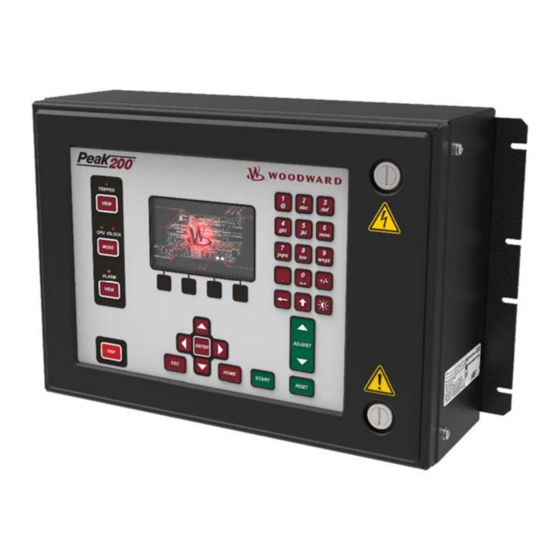
Page 28: Figure 2-2. Peak200 Bulkhead Unit
Peak200 unit has the identical mounting hole pattern as the Peak150, however power and I/O terminal block placement and size within the unit do not match Peak150 pattern. Check table below for details. Peak200 unit does NOT feature RS-422 communication interface. Woodward... -
Page 29: Wiring Differences Between Peak150 And Peak200
Dimensions: 19” x 12” x 4” Dimensions: 19” x 12” x 4” Opens from left to right Opens from right to left Woodward provided bushings Customer needs to mount bushings Power input: Power input: Wires gauge limits: min 24 AWG max 10 AWG... - Page 30 Wires gauge limits: min 28 AWG max 16 AWG Wire mount method: screw connection with Wire mount method: screw connection to pluggable tension sleeve to PCB terminal block connector Connector pins: 6 pins, SPEEDX+, SPEEDX-, 2x Connector pins: 6 pins, SPEEDX+, SPEEDX-, 2x SHIELD pin SHIELD pin Woodward...
- Page 31 There is a service port to configure Peak200 VXWorks system for use. There are additional communication ports: CAN, Ethernet ports The physical outline dimensions for the Peak200 control are shown below. See Woodward Reference drawing 9989-1335 for additional details if necessary. Woodward...
-
Page 32: Figure 2-3. Peak200 Bulkhead Mount Version Outline Drawing
Released Manual 35051 Peak®200 Digital Control for Steam Turbines Figure 2-3. Peak200 Bulkhead Mount Version Outline Drawing. Woodward... -
Page 33: Panel Version Mounting Information
Use screw 1069-949 (.375 Long, 10-32) for panel thickness (including washers) .065” - .100" • Use screw 1069-948 (.438 Long, 10-32) for panel thickness (including washers) .101”- .125” • Use screw 1069-946 (.500 Long, 10-32) for panel thickness (including washers) .126” - .187” Woodward... -
Page 34: Figure 2-5. Peak200 Front Panel Mount Version Outline Drawing
Released Manual 35051 Peak®200 Digital Control for Steam Turbines See Woodward Reference drawing 9989-1337 for additional details if necessary. Figure 2-5. Peak200 Front Panel Mount Version Outline Drawing. Woodward... -
Page 35: Input Power Specification
4mm² (12AWG). Visual Indicators (LED’s) & CPU Configuration Visual indicators are located on the Front Panel keypad, the controller board, back cover, and related communications ports for diagnostic use. CPU OK indicator (green/red) Woodward... -
Page 36: Communications (Ethernet)
Features • Interface standard: IEEE 802.3 (Ethernet) • Port Isolation: 1500 Vrms to PS, EARTH, and all other circuits • Control configuration using Woodward AppManager • Control monitoring, trending, and Datalog collection • Control configuration of Ethernet IP addresses •... -
Page 37: Table 2-4. Ethernet Ports #1-2 (10/100)
Note: Ports #3 and #4 are disabled and blanked off. Network Configuration Utility (AppManager) Woodward's AppManager™ software can be used to configure network setting and load Control software (GAP), HMI display software (QT), and operating system service packs. The AppManager utility can be downloaded from www.woodward.com/software. -
Page 38: Table 2-6. Can Connector Pinout
Max wire size: 1.3 mm² / 16 AWG for single wires, 0.5 mm² / 20 AWG for two wires CAN Cable Specifications Belden YR58684 (Woodward PN 2008-1512) communications / CAN cable is approved and recommended. This is a smaller and more flexible 0.3 mm² / 22 AWG, low capacitance cable suitable for tight routing in industrial environments. -
Page 39: Figure 2-6. Com1 Example Rs-485 Wiring
Flex500 / Peak200 hardware products). However, the shield must also be directly terminated to chassis (Earth) at one point in the network. In the case of Woodward equipment, locate the direct ground at the master device end, as it exits the master device’s enclosure. -
Page 40: Hardware - Terminal Blocks & Wiring
Released Manual 35051 Peak®200 Digital Control for Steam Turbines Hardware - Terminal Blocks & Wiring Back cover view with wiring label. Figure 2-7. Peak200 Back Cover Label – Bulkhead Woodward... -
Page 41: Figure 2-8. Peak200 Back Cover Label - Front Panel Mount
Released Manual 35051 Peak®200 Digital Control for Steam Turbines Figure 2-8. Peak200 Back Cover Label – Front Panel Mount Woodward... -
Page 42: I/O Signal Specifications And Wiring
This controller includes two (2) Digital Speed Sensor circuits that are capable of interfacing to MPU speed probe sensors. Features Two (2) Digital Speed Sensor circuits, isolated individually Woodward GAP block, diagnostics, and configuration support GAP configurable update rates of 5 ms to 160 ms Woodward... -
Page 43: Figure 2-10. Speed Sensor Block Diagram
Differential inputs with high common-mode voltage capability Isolated Loop Power +24 V is provided with short-circuit protection Woodward GAP block, diagnostics, and configuration support GAP configurable update rates of 5 ms to 160 ms GAP configurable for Loop power operation Table 2-10. -
Page 44: Figure 2-11. Analog Input - Self-Powered Block Diagram
Group isolated from other circuits Capable of driving higher impedance loads up to 600 ohms Woodward GAP block, diagnostics, and configuration support GAP configurable update rates of 5 ms to 160 ms Table 2-11. Specifications (AO) Number of channels... -
Page 45: Figure 2-13. Analog Output Block Diagram
Isolated from other circuits Capable of driving higher impedance loads Woodward GAP block, diagnostics, and configuration support GAP configurable update rates of 5 ms to 160 ms Table 2-12. Specifications (ACT) Number of channels (1) proportional driver with source & return readbacks... -
Page 46: Figure 2-14. Actuator Output Block Diagram
+24 V Contact Power with short-circuit and diode protection Isolated power and discrete input group Woodward GAP block, diagnostics, and configuration support GAP configurable update rates of 5 ms to 160 ms Time-stamping capability (1 ms) Table 2-13. -
Page 47: Figure 2-15. Discrete Input Block Diagram
Each Relay Output provides NO, COM, and NC contacts Each Relay Output channel provides a coil voltage readback fault Woodward GAP block, diagnostics, and configuration support Contact isolation maintained at terminal blocks ATEX approved version available using hermetically sealed relays ... -
Page 48: Troubleshooting Fault Codes
Verify PS(+) and PS(–) impedance to EARTH is > 10 MΩ RS-232 wiring checks Verify the RS-232 wiring uses a high quality shielded communication cable. For example, Woodward 2008-1512 (Belden YR58684) or equivalent low capacitance, shielded communications wire. ... - Page 49 CAN wiring checks Verify the CAN wiring uses a high quality, 3-wire, shielded communication cable. For example, Woodward 2008-1512 (Belden YR58684) or equivalent low capacitance, shielded communications wire. Verify CAN network length is < max length spec for the baud rate being used ...
- Page 50 Verify each RTD shield wire is terminated at the node properly. Functionally verify the wiring for each RTD channel using a simulator source. RTD OPENS: RTD channels will read MAX DegC if the (+) or (–) wire is broken. Woodward...
-
Page 51: Chapter 3. Control Description
The Speed Relationship diagram (Figure 3-1) shows how the speed settings in the Peak200 relate to each other, and may be helpful when configuring the Peak200 speed setpoints Figure 3-1. Speed Relationships Front Panel View Figure 3-2. Front Panel The keypad is the same on the Bulkhead or Panel mounted versions. Woodward... -
Page 52: Four Fixed Operational Action Buttons On Front Panel
1, drives the VALVE RAMP (ACTUATOR) to zero (closed position), and changes the state of the TRIP RELAY. In the Service menu, there is an option to add a 2-second delay to this command to prevent nuisance trips if the button is pressed accidentally. The default setting of this delay is zero (immediate). Woodward... -
Page 53: User Login Levels
Mode screen. Navigating to this icon and pressing Enter will open a pop-up dialog box that will allow the user to select a language other than English for the local display. Figure 3-4. Language Woodward... -
Page 54: Navigation
This is NOT a touchscreen! Due to quality, robustness, screen cleanliness, and long-term reliability concerns Woodward chose not to implement a touchscreen directly on this product. Using the RemoteView tool a user can take advantage of either a mouse device or a touchscreen on an external computer, but for navigation and selection directly on the Peak200 display, buttons and an IN-Focus highlighter indication are used. -
Page 55: Page Organization
Peak200. When the unit is in Configure Mode (IOLOCK) the background of all pages will be a blue gradient as shown below, in addition to the status in the upper right. Figure 3-7. Configuration Menu – Operation Mode (View only) Woodward... -
Page 56: Start Modes
START command). For either of these modes the HOME/STARTUP CURVE menu is the ideal screen to monitor while starting the turbine. Initially the user may need to also use the Speed Control menu to adjust the control dynamic settings. Woodward... -
Page 57: Figure 3-9. Startup Curve Screen
Once the turbine is safely in speed control, the limiter will automatically continue on to the maximum setting of the valve limiter (usually 100%) To enable this feature: Service / Valve Demand – Use HP Start Limiter? HP Max Limiter at Start (%) Woodward... -
Page 58: Operating Mode (Setting Turbine Speed)
If while the contact input is held TRUE and the analog input fails, the control will automatically re- enable using the remote speed setpoint as soon as the analog input signal is repaired and reset. (Caution – users need to consider their plant operation to consider whether this action is desirable or undesirable). Woodward... -
Page 59: Process/Cascade Control
When enabled, the Cascade PID can move the speed set point at a variable rate up to the ‘Max Speed Set Point Rate’ setting (programmed under the CASCADE CONTROL header). Figure 3-10. Cascade Functional Diagram Woodward... -
Page 60: Table 3-1. Cascade Control Status Messages
To use this controller an analog input channel must be configured for use as the Process/Cascade input. The Peak 200 will use this input as the Process Variable (PV) for this controller. If at any time while in Cascade control this PV faults, the Cascade controller will be disabled and the speed setpoint will remain at its current setpoint (bumpless). - Page 61 Service mode). If Cascade is the controlling parameter and one of the permissives is lost or Cascade is disabled, the speed set point will remain at its last setting until another parameter adjusts it. Woodward...
- Page 62 Point is positioning the Cascade set point. Inhibited—Remote Set Point cannot be enabled; input signal is failed, Cascade input signal is failed, a controlled stop is selected, the unit is shut down, or the remote cascade control is not programmed. Woodward...
- Page 63 Control and Remote Cascade Control must be enabled either from the front panel keypad or from Modbus. Since the front panel and Modbus provide both Remote Cascade Enable and Cascade Control Enable commands, they will operate in the same manner as ‘both enables programmed’. Woodward...
-
Page 64: Chapter 4. Configuration Procedures
These user levels are: Monitor Operator Service Configure In addition to granting authority to enter and exit modes, user levels also determine what parameters the user is authorized to adjust. See Table 4-1, Mode Access by User Level. Woodward... -
Page 65: Mode Descriptions
The Service user level allows the same commands as the Operator user level plus tuning of Service menu parameters and issuing of additional commands. The Configure user level allows the same commands and access as the Service user level plus tuning of Configuration menu parameters. Woodward... -
Page 66: Figure 4-1. Initial Home Screen (Unit Not Configured)
“Configure” User Level or greater is logged in 6. Press MODE or HOME to return to the HOME screen. 7. Press the Configuration softkey to access the configuration menus. 8. Use the navigation cross to navigate up/down/left/right and use ENTER to select a menu or item. Woodward... -
Page 67: Using Configure Menus
The first four configure menus listed below, as well as drivers and other I/O, must be programmed for every installation. The remaining menus contain optional features which can be selected if desired. The configure menus and their basic functions are described below. Woodward... -
Page 68: Figure 4-2. Configuration Menu - Configuration Mode (Edit) With Error
(shown in parentheses). Note: For users that are familiar with the Peak 150 hand-held programmer – the following table is a quick reference to where those parameters are found in the Peak200 configuration menu above. Woodward... -
Page 69: Table 4-3. Peak150 To Peak200 Configuration Parameter Locations
If selected will allow operator to ramp back to Idle from MinGov. If unselected the unit will not accept a command to return to Idle speed – the operator can still manually take control of the setpoint and return to Idle speed Woodward... - Page 70 For example, if the turbine revolves twice for every revolution of the MPU gear, enter 2 for the “MPU GEAR RATIO 1”. The following is the equation for calculating the MPU Gear Ratio 1: Woodward...
- Page 71 To the right of this a suggested value is shown – make this value equal to or greater than value shown) Note: the suggested values displayed are calculated from the Speed Setpoints entered by the user – once those have been entered, these suggested values will be updated. Woodward...
- Page 72 (This is the exact same variable that was available in the Turbine Start menu) Underspeed Setpoint (rpm) _________ Underspeed setpoint during normal operation – if the turbine falls below this speed during normal operation an alarm will be annunciated Woodward...
- Page 73 Select this to enable the use of the Modbus slave communication block Use Serial Port (Modbus Link 1)? _________ Select this to use the serial communication port for Modbus Use Ethernet 1 Port (Modbus Link 2)? _________ Select this to use the Ethernet communications port for Modbus Woodward...
- Page 74 This menu is used to configure an optional process control loop. The output of this PID control will determine the setpoint for the speed control. In Woodward terminology, we refer to this as a ‘Cascade’ control, since its output drives the setpoint for another PID rather than controlling the valve demand directly.
-
Page 75: Table 4-4. Analog Input Options
Bearing Temperature #2 Process/Cascade Input Bearing Temperature #3 Remote Cascade Setpoint Bearing Temperature #4 Vibration Input #1 Signal Monitoring #1 Vibration Input #2 Signal Monitoring #2 Vibration Input #3 Signal Monitoring #3 Vibration Input #4 HP Valve Feedback Position Woodward... - Page 76 All 4–20 mA analog readouts may be configured. The function that the readout uses must be programmed or an error message will occur. For example, to use the Process/Cascade Set Point readout, the ‘Use Process/Cascade’ function must be programmed. ANALOG OUTPUT # 1 Output Function (must choose from list) Woodward...
-
Page 77: Table 4-5. Analog Readout Options
20-160 mA actuator select the 0-200 mA range. Dither (mA) dflt= 0.0 (0.0, 10) Enter the dither mA for the actuator channel. Enter 0.0 if no dither is required. Woodward TM-type actuators typically require dither. Device Tag This is a user entered field. -
Page 78: Table 4-6. Contact Input Options
This channel is a dedicated trip output. Device Tag This is a user entered field. It allows entry of a short description or tag name for this channel. Invert Logic? dflt= NO (Yes/No) Check this box to invert the active state of the relay Woodward... -
Page 79: Table 4-7. Options For Relays Ff Used To Indicate State
0.0 (-1.0e+38, 1.0e+38) Enter the level switch OFF setting in engineering units. (Must be less than the ‘Relay On Level’ Setting) Relay outputs # 2 through # 4 are entered following the same rules as described for Relay above. Woodward... - Page 80 Appendix I), this menu will become available under the Configuration menu. This section allows you to expand the I/O capability of the Peak200 through the use of Woodward LinkNet HT distributed I/O nodes. All LinkNet (LN) nodes are connected via the CAN port 2 and should be configured for a Baud rate of 500K.
-
Page 81: Table 4-9. Ln Analog Input Function Options
Set the value that corresponds to the lowest temperature expected to be seen as a valid signal Maximum Value (Temp Units) dflt= 1500 (-1.0e+38, 1.0e+38) Set the value that corresponds to the highest temperature expected to be seen as a valid signal (Must be greater than the ‘Minimum Value’ Setting) Woodward... -
Page 82: Table 4-10. Ln Rtd Input Function Options
-10.0 (-100, 100) Enter a hysteresis value here that will be applied to the speed setpoint. This is useful if the speed setpoint is at an idle speed setting, where the turbine speed may be held, and fluxuate around this speed Woodward... -
Page 83: Table 4-11. Ln Discrete Contact Input Options
This is a user entered field. It allows entry of a short description or tag name for this channel. Invert Logic? dflt= NO (Yes/No) Use to invert the normal status of the contact output. In the event of a control power failure, the contact will return to its normal state. Woodward... -
Page 84: Table 4-13. Options For Level Switch
Number of healthy signals required to run (1-4)? dflt= 0 (1,4) Enter minimum total number of channels required to keep running. If this number equals the number of channels used, then a single channel fault will result in a Trip Woodward... -
Page 85: Chapter 5. Operating Procedures
The Peak200 control has been designed to run 2 separate, independent programs on the same platform. One controls the I/O and therefore controls turbine operation. The other program provides all the visual and command interaction with the user. Peak 200 Turbine Control Woodward GAP GUI Application Control Application 5418-7345_Rev.wgui... -
Page 86: Front Panel Operation
Viewing the front panel display of the Peak200 – the following is the correct boot-up sequence of the control. Times are approximant. At Power-up Screen = BLANK /BLACK IOLOCK = ON (RED) After about 0:45 Screen = “Woodward Splash Screen” TRIPPED/CPU/ALARM LED’s will flash check After about 1:00 TRIPPED=ON (RED) IOLOCK = OFF... -
Page 87: Figure 5-3. Boot-Up To Home Screen (Remoteview)
The disabling of these features is available for troubleshooting – or for cases where the Peak200 is packaged in a way were screen and keypad access is not available. Woodward... -
Page 88: Control Mode Architecture
Power-up. All I/O is functional in this state. The turbine may be either running or not running in this mode. The Peak 200 is defaulted to always boot-up into operational mode. If required by the site, there is a service parameter to change this so it will boot-up in monitor mode. -
Page 89: Overview
The menu bar functions will allow the user to access a number of other screens that are related to speed control, such as directly entering a setpoint, access to the valve limiter feature, adjusting speed control dynamic settings, enabling or disabling a remote speed setpoint or performing an Overspeed test. Woodward... -
Page 90: Valve Demand
During normal run operation, this screen provides the user with information similar to the Overview, but in a graphical gauge view. It provides larger values for distance viewing and control PID information that is useful for monitoring when the Peak200 is near transition points between controllers or limiters. Figure 5-8. Controllers Screen Woodward... -
Page 91: Cascade Control
The Analog Input Summary screen will display the status of all channels available on the Peak200 hardware. The fault status, function, device tag, engineering value and units display for each channel as well as navigation buttons for each channel that take the user to a page showing all parameters available for that input. Woodward... -
Page 92: Contact Input Summary
The Contact Input Summary screen will display the status of channels available on the Peak200 hardware. The fault status and function display for each channel. Use the Details navigation button to view the full configuration of each channel. Figure 5-11. Contact Input Summary Screen Woodward... -
Page 93: Analog Output Channel
The Relay Output Summary screen will display the status of all channels available on the Peak200 hardware. The coil status, function, and device tag display for each channel. Use the Details navigation button to view the full configuration of each channel. Figure 5-13. Relay Output Summary Screen Woodward... -
Page 94: Actuator Driver Summary
Figure 5-15 shows the screen that displays when pressing the ‘Overspeed Test’ key from the Speed Control page. It shows the permissives required to be able to perform an overspeed test. Figure 5-15. Overspeed Test Permissives Woodward... -
Page 95: Figure 5-16. Internal (Peak200) Overspeed Test
To perform an Internal Overspeed Test Press the Enable Int Test key and the above pop-up page will appear. An Alarm will be annunciated that indicates Overspeed Test Enabled Put the Adjust button in Focus and use the ADJUST key to raise the speed above the normal Max Governor limit. Woodward... -
Page 96: Figure 5-17. External Overspeed Test
The intention of an external trip test is to test the unit’s safety overspeed protection device (in many cases a Woodward Protech). In this mode, the Peak200 internal overspeed trip changes to be just an alarm and the Peak200 will allow the speed to continue increasing up to the Overspeed Test Limit (rpm). If the Peak200 speed OR the Setpoint reaches the Overspeed Test Limit, it will TRIP the turbine ... -
Page 97: Alarm Summary
Figure 5-18. Alarm Summary Screen Each individual alarm condition is available through the Modbus links to monitor the control status. The system also provides a common alarm indication. Woodward... -
Page 98: Table 5-1. Alarm Messages
- not used spare_19 reserved - not used spare_20 External Alarm #1 from contact input External alarm # 1 External Alarm #2 from contact input External alarm # 2 External Alarm #3 from contact input External alarm # 3 Woodward... - Page 99 AI Chan 2 Level 2 ALM setpoint Analog Input chan 3 user configured alarm at level 1 AI Chan 3 Level 1 ALM setpoint Analog Input chan 3 user configured alarm at level 2 AI Chan 3 Level 2 ALM setpoint Woodward...
-
Page 100: Shutdown Summary
To clear any shutdowns that are no longer present, press the RESET key, close the Reset contact input, or select Reset from either Modbus communications link. If the cause of the event has been corrected, the event will clear, if not it will remain, and the time-stamp will remain unchanged. Woodward... -
Page 101: Figure 5-19. Shutdown Summary Screen
AI Chan 4 Level 2 TRIP Analog Input chan 4 reached TRIP Level 2 Summary TRIP from LinkNet IO Summary Trip from a device on the LinkNet IO At Overspeed Test Max Setpoint During External OSPD test Max setpoint was reached Woodward... -
Page 102: Speed And Cascade Dynamics Adjustments
(SPEED and CASC). To adjust the gain settings, the In-Focus highlighter must be on the component value to tune. You move the In-Focus highlighter using the navigation Cross. The ADJUST UP and DOWN keys can then be used to adjust the function In-Focus. Figure 5-20. Speed Dynamics Adjustment Screen Woodward... - Page 103 200’s adjustable gains. If the accumulated mechanical gain (actuators, valves, valve linkage, etc.) is very high, the Peak 200’s gain must be very low to be added to the system gain required for system stability. In cases where a small change in the Peak 200's output results in a large speed or load change (high mechanical gain), it may not be possible to take the Peak 200's gains low enough to reach stable operation.
-
Page 104: Figure 5-21. Typical Response To Load Change
PID’s response to that of the entire control loop (controller, actuator, valve, turbine, and speed input signals). Figure 5-28 shows the typical response to a load change when the dynamics are optimally adjusted. Figure 5-21. Typical Response to Load Change Woodward... - Page 105 Peak®200 Digital Control for Steam Turbines The above information is the traditional information for tuning Woodward’s implementation of a PID. Initially these steps should be followed to gain reasonably stable speed control. The Peak200 control also contains a new automated PID Optimization routine that can be used on the Speed PID.
-
Page 106: Starting Procedures (Start Curve Screen)
Figure 5-22. HOME Menu showing “Startup Curve” IN-Focus Refer to the turbine manufacturer’s operating procedures for complete information on turbine start up, and Chapter 3 of this manual for a step-by-step procedure, depending on the start mode selected. The following is a typical start- up procedure: Woodward... - Page 107 Press the START button on the front panel, once the unit has started and reached Idle speed, repressing the START key will command the control to ramp up to Min Governor speed This ramp will accelerate the turbine at the Rate to Minimum rate. Woodward...
-
Page 108: Critical Speed Band Avoidance
(from 0-100%), the actuator signal will follow this value (The actuator output range is selected in the ACTUATOR CONFIGURATION MENU as either 4-20 mA or 0-200 mA). Woodward... -
Page 109: Speed Control Screen
The remote speed setpoint is defined by an analog input signal. The minimum (4mA) and maximum (20mA) values for this range must be set equal to or within the range set by the values assigned to the MIN GOV SPEED and the MAX GOV SPEED respectively. Woodward... -
Page 110: Shutdown And Alarm Function Summary
SPEED CONTROL (100%-Open). When the control gets a TRIP command, the VALVE RAMP over rides the SPEED CONTROL and closes the ACTUATOR (0%-Closed). The SPEED CONTROL increases or decreases the steam demand signal during normal turbine operation. Woodward... -
Page 111: Manual Valve Demand (Ramp) Control
Rolldown Delay, the MPU’s override is switched on. This prevents a LOSS OF BOTH MPUs trip, and drives the Peak200 governor valve opens fully as turbine speed decreases. A sudden loss of the MPU inputs trips the turbine and closes the governor valve. Woodward... -
Page 112: Actuator Calibration/Stroking Procedure
Press the ‘Save Settings’ softkey to permanently save any minimum or maximum actuator settings into the Peak 200. If variables are tuned or changed but not stored to a file, then those changes will be lost if power is removed from the control or if the control receives a CPU reset. -
Page 113: Chapter 6. Modbus Communications
RS-232 connections. Figure 6-2 shows typical RS-232 communications connection. The transmit data (TXD), receive data (RXD), and signal ground (SIG GND) must be properly connected as shown. In addition, the shield (SHLD) should be connected at one end only. Woodward... -
Page 114: Basic Modbus Overview
Table 6-1). The default slave address for the Peak200 control is 01, however, this address is adjustable in the configure mode. On any single link, each slave address must be unique. Modbus Points of Interest Master, Slave network protocol One master and up to 32 slaves on a common line Woodward... -
Page 115: Figure 6-4. Basic Modbus Overview
ASCII Beginning of Frame 3 Characters Dead Time Slave Address 2 Characters, 8 Bits 1 Character, 8 Bits Function code 2 Characters, 8 Bits 1 Character, 8 Bits Data 4 Bits Data per Character 8 Bits Data per Character Woodward... -
Page 116: Table 6-3. Modbus Function Codes
The message function is not an allowable action Illegal Data Address The message start address is not an allowable address Checksum Error The received message had an incorrect error check code Garbled Message The received message could not be decoded Woodward... -
Page 117: Modbus Addresses
Boolean reads and writes are also referred to as input and holding coils. The analog reads are also referred to as input registers. Following is a list of these register values along with a brief description of the parameter. Woodward... -
Page 118: Table 6-5. Available Holding Coils
Block Output Name (for OPC) Address Description Shutdown Exists (Trip Indication) SHUTDOWNS.ANY_SD.B_NAME 1:0001 Alarm Exists (Common Alarm ALARMS.ANY_ALM.B_NAME 1:0002 Indication) Alarm - MPU #1 Failed ALARMS.ANY.SEL_1 1:0003 Alarm - MPU #2 Failed ALARMS.ANY.SEL_2 1:0004 Alarm - Remote Speed Input Failed ALARMS.ANY.SEL_3 1:0005 Woodward... - Page 119 1:0045 Relay Output 4 State CNFG_BO.RELAY_4.DISPLAY 1:0046 LN Node 4 DI 1 State MOD_LN_IO.LN_B_STATES.LIST_1 1:0047 LN Node 4 DI 2 State MOD_LN_IO.LN_B_STATES.LIST_2 1:0048 LN Node 4 DI 3 State MOD_LN_IO.LN_B_STATES.LIST_3 1:0049 LN Node 4 DI 4 State MOD_LN_IO.LN_B_STATES.LIST_4 1:0050 Woodward...
-
Page 120: Table 6-7. Available Input Registers
Actual Turbine Speed (RPM) MPU.TURB_SPD.A_NAME 3:0002 Speed Setpoint (RPM) SPD_CTRL.SPD_SETPT.A_NAME IFACE_OUT_SPEED.RMT_SPD_INPUT.A_NAM 3:0003 Remote Speed Setpoint 3:0004 Remote Speed Setpoint Input AI_MUX.RMT_SPD_SP.A_NAME 3:0005 VLV Limiter Output x 100 MOD_SCALE.VLV_100.MULTIPLY 3:0006 Speed PID Output (%) x100 MOD_SCALE.SPD_100.MULTIPLY 3:0007 HP Actuator Demand (%) x100 MOD_SCALE.ACT1_HSS.MULTIPLY Woodward... - Page 121 TRIPS with Load/Valve > 75% COND_MON.SDLOAD2_NUM.A_NAME 3:0045 Overspeed TRIPS Counter COND_MON.OSPD_NUM.A_NAME 3:0046 Total Run Time Hours COND_MON.TRUNHRS.A_NAME 3:0047 Total Run Hours with Load/Valve > 25% COND_MON.TRUNLDHRS.A_NAME 3:0048 Total Run Hours with Load/Valve > 75% COND_MON.TRUNLD2HRS.A_NAME 3:0049 Spare_49 3:0050 Spare_50 Woodward...
-
Page 122: Table 6-8. Available Holding Registers
3, 6, and 16. These correspond to read analog output, write single analog output, and write analog outputs respectively. Table 6-8. Available Holding Registers Address Description Multiplier Modbus Entered Speed Setpoint '(1) 4:0001 Modbus Entered Casc Setpoint '(1) 4:0002 '(1) 4:0003 '(1) 4:0004 '(1) 4:0005 Woodward... -
Page 123: Chapter 7. Service Menus
If YES – each new alarm will cause LED and Relay to blink whenever a new alarm is triggered Internal Operating Temp (degrees C) (status indication only) Shows internal temperature of the control Screen Brightness Level (%) (status indication only) Adjusted with keypad brightness & adjust keys Woodward... -
Page 124: Speed Control Menu
Droop% * Min Gov Setpoint * Valve Demand and subtract this value from the setpoint. This is typically left at 0% (default) for mechanical drive applications. When this is used – an offset will always exist between the Setpoint and the Speed. Woodward... - Page 125 Speed at which speed control dynamics switch from Offline to Online Use Reduced Overspeed Setpoint ______________ Allows the use of a separate variable for overspeed tests and enables Overspeed Trip function within the MinGov to Max Gov speed range Woodward...
-
Page 126: Valve Demand Menu
*TRUE (PEAK200_IO.USE_HALF.CTRL) SNTP IP address ______________ Set the LAN IP address for the clock synchronization SNTP Rate (sec) ______________ Set time rate at which the control will sync to the LAN clock Woodward... -
Page 127: Cascade Control Menu
Fast Rate of cascade setpoint adjustment Entered Rate (units/sec) ______________ Rate of cascade setpoint ramp to the entered value Droop (%) ______________ Percent of droop added to process signal (this will create an offset between the control PV and the actual setpoint) Woodward... -
Page 128: Communications Menu
Enables the use of override timer once Start has been initiated Override Time (sec)? ______________ Sets the time the override will be active once Start has been initiated Override Time remaining (status only) ______________ Enables the use of override timer once Start has been initiated Woodward... -
Page 129: Operation Log Menu
Run Time Hours with Load (Valve) > 75% (status indication only) Total hours of turbine runtime at high load Peak Speed Reached (status indication only) Maximum speed registered by the control Maximum Acceleration Reached (status indication only) Maximum acceleration registered by the control Woodward... -
Page 130: Chapter 8. Troubleshooting
The CPU board runs diagnostics that display troubleshooting messages through the debug Service Port and AppManager. Additional information on diagnostics tests, subsequent LED flash codes, and serial port messages is contained in the VxWorks manual. Table 8-1 shows the CPU fault LED flash codes: Woodward... -
Page 131: Troubleshooting Chart
All keypad LED’s are off and display is blank. Possible Causes: Power supply input wiring is incorrect. Power supply input voltage is not present. Power supply fuse is blown. Solution: Check the possible causes listed above. Woodward... - Page 132 Check the software to see what it senses at the inputs. Go to Contact Inputs from the HOME page and view the status LED of each channel. Also look at the Details of any specific channel in question to verify whether the active state of the Function defined as been inverted Woodward...
- Page 133 Use the Calibration mode to Force the actuator driver output and verify proper functioning of the channel in question Symptom: Speed sensor inputs are not operating correctly. Possible Causes: Incorrect wiring. The magnetic pickup is not functioning properly. Only MPU’s are supported Configuration of teeth/gear ratio is incorrect Woodward...
- Page 134 The CPU LED should always be on and GREEN. If it is not, see the "CPU Flash codes in the diagnostic section": Typically if it is solid RED or giving a flash code, it will require a power cycle to possibly clear the issue. Woodward...
-
Page 135: Alarms / Shutdowns
If actual speed is less than the speed called for by the speed reference, check for speed droop. Droop causes the actual speed to be less than the speed reference. If the Remote Speed input values are reading incorrectly, ensure the input wire shielding is properly grounded at the Peak200 control end only. Woodward... -
Page 136: Chapter 9. Product Support And Service Options
An Authorized Independent Service Facility (AISF) provides authorized service that includes repairs, repair parts, and warranty service on Woodward's behalf. Service (not new unit sales) is an AISF's primary mission. A Recognized Turbine Retrofitter (RTR) is an independent company that does both steam and gas turbine control retrofits and upgrades globally, and can provide the full line of Woodward systems and components for the retrofits and overhauls, long term service contracts, emergency repairs, etc. -
Page 137: Returning Equipment For Repair
All repair work carries the standard Woodward service warranty (Woodward Product and Service Warranty 5-01-1205) on replaced parts and labor. -
Page 138: Replacement Parts
The unit serial number, which is also on the nameplate Engineering Services Woodward offers various Engineering Services for our products. For these services, you can contact us by telephone, by email, or through the Woodward website. Technical Support ... -
Page 139: Technical Assistance
Peak®200 Digital Control for Steam Turbines Technical Assistance If you need to contact technical assistance, you will need to provide the following information. Please write it down here before contacting the Engine OEM, the Packager, a Woodward Business Partner, or the Woodward factory: General... -
Page 140: Appendixa Configuration Mode Worksheets
GAP runs the control (I/O) application and the WGUI controls the graphical user interface screens GAP Application ID __________________________________ WGUI Application ID __________________________________ Customer Site Name __________________________________ Location __________________________________ Woodward... - Page 141 Use Remote Speed Setpoint? YES/NO Remote Speed Setpt Max Rate rpm/sec Rmt Spd Setpt Not Matched Rate rpm/sec Use DI Enable/Disable as Momentary? YES/NO Use Critical Speed Avoidance? YES/NO Critical Speed Rate rpm/sec Critical Speed 1 Minimum Critical Speed 1 Maximum Woodward...
- Page 142 Speed Setpoint Upper Limit Max Speed Setpoint Rate rpm/sec Cascade Droop Cascade PID Prop Gain Cascade PID Integral Gain Cascade Derivative Ratio (SDR) Use Remote Casc Setting YES/NO Remote Casc Max Rate Units/sec Cascade Units of Measure Decimals Displayed on Display Woodward...
- Page 143 0.01 -100 Decimals Display on Screen Gain Offset Analog Input #4 - Value at 4 mA Value at 20 mA Input Function Device Tag Loop Powered? YES/NO Engineering Units Modbus Multiplier 0.01 -100 Decimals Display on Screen Gain Offset Woodward...
- Page 144 Input Function Device Tag Invert Logic? YES/NO Contact Input #6 - Input Function Device Tag Invert Logic? YES/NO Contact Input #7 - Input Function Device Tag Invert Logic? YES/NO Contact Input #8 - Input Function Device Tag Invert Logic? YES/NO Woodward...
- Page 145 Value at 20 mA Input Function Device Tag Engineering Units Enable Readback Fault YES/NO Gain Offset Analog Output #3 - Value at 4 mA Value at 20 mA Input Function Device Tag Engineering Units Enable Readback Fault YES/NO Gain Offset Woodward...
- Page 146 Actuator Function HP Dmd Actuator Range (0-20 / 0-200) Dither (mA) Device Tag Use Actuator Fault as Shutdown YES/NO Invert Actuator Output? YES/NO Gain Offset Use Self-Powered Actuator YES/NO MPU OVRD to this % of MinSpd Self-Powered Time Delay (sec) Woodward...
- Page 147 Chan Flt = SD? YES/NO Chan Fault Delay (sec) Level 1 Setpoint Invert Action at Level 1? YES/NO Level 2 Setpoint Invert Action at Level 2? YES/NO Setpoint Hysteresis Delay for Event action (sec) Enable Speed Setpoint (rpm) Speed Setpoint Hysteresis Woodward...
- Page 148 Enable Speed Setpoint (rpm) Speed Setpoint Hysteresis LinkNet Nodes (for additional I/O) Optional Enable Using LinkNet HT I/O Nodes? YES/NO Enable Node 1 (AI/AO)? YES/NO Enable Node 3 (RTD)? YES/NO Enable Node 4 (BI)? YES/NO Enable Node 5 (BO)? YES/NO Woodward...
-
Page 149: Appendixb Service Mode Worksheets
REALTIME CLOCK Use SNTP Time Synchronization? YES/NO Time Zone SNTP IP Address SNTP Rate SNTP Timeout MPU OVERRIDE Use MPU Override Timer? YES/NO Override Time (sec) Override Time Remaining Use Rolldown Override? YES/NO Rolldown Speed (rpm) Rolldown Delay (sec) Woodward... - Page 150 YES/NO HP Manual Demand Rate (%/s) %/sec Manual Demand Timeout Limit COMMUNICATIONS Use Modbus Trip? YES/NO Enable Link 1 Writes (Serial)? YES/NO Enable Link 2 Writes (ENET 1)? YES/NO Link 1 Timeout Delay (Serial) Link 2 Timeout Delay (Ethernet) Woodward...
- Page 151 Trips with Load/Valve > 25% Trips with Load/Valve > 75% Overspeed Trips Total Run Time Hours Runtime with Load/Valve > 25% Runtime with Load/Valve > 75% Peak Speed Reached Max Acceleration Detected rpm/sec TRENDS no user settings - views only Woodward...
-
Page 152: Appendixc Automatic Speed Pid Dynamic Analysis
The trend below gives an overview of the entire Optimization routine. The actuator demand displayed in yellow, speed setpoint in white, and speed in red. The left portion of the trend is the Analysis Mode. The right portion of the trend is the Setpoint Step Mode. Woodward... -
Page 153: Figure C-2. Speed Vs Actuator Trends During Analysis
On the front panel, the status will progress through the following steps during the Setpoint Test Mode: Settling at Setpoint Step Tests with OPTI Gains System Settling Complete – Using New Gains Woodward... -
Page 154: Figure C-3. Speed Pid Optimizer Configuration
This value limits how much the actuator demand will move during the Analysis Mode when the turbine is using Online dynamics. The percentage will limit the output +/- from the actuator position when the optimizer is enabled. The optimizer will not abort if this limit is reached, but an alarm will be annunciated. Woodward... - Page 155 The process loop (like speed) controlled by the PID is too fast for the rate group (RG) of If the control loop is position droop, the problem may be that there is no lag or other filter on the between the PID output and the process input. Woodward...
- Page 156 This alarm indicates high deadtime in the system, relative to the system bandwidth. Deadtime is typically measured on a step and is defined as the amount of time between when the SP starts to move, and when the process starts to move. Woodward...
- Page 157 The CLR_STATE input was toggled TRUE This can occur when system dynamics are changed from Offline to Online Some solutions for this fault would include: Ensure that the CLR_STATE logic is correct; CLR_STATE has priority over automatic tuning. Woodward...
- Page 158 Some solutions for this fault would include: Monitor the performance of the system, including the valve, steam pressure, hydraulic pressure, etc. Use a Datalog to verify proper I/O to the PID Woodward...
- Page 159 The Droop Limit is too low. The Act Limit is too high; resulting in actuator movements that are too large for the Droop Limit (this is unlikely). Woodward...
- Page 160 1.0 in either direction. For example, this fault will be annunciated if S_D_R is 0.5 when the optimizer is started and subsequently S_D_R changes to 1.1 while the optimizer is active. Similarly, this fault will also be annunciated if S_D_R transitions from greater than 1.0 to less than 1.0 while the optimizer is active Woodward...
-
Page 161: Appendix D Servlink-To Opc Server (Sos) Tool
The Woodward SOS Servlink OPC server ("SOS") provides an OPC interface for Woodward controls. It runs on a Windows PC that accesses data on controls using the Woodward proprietary Servlink protocol through an Ethernet connection. Woodward OPC client applications, such as Monitor GAP and Control Assistant connect to SOS by selecting a 'Servlink OPC server' connection. -
Page 162: Connecting A Pc/Laptop To The Control
Servlink-to-OPC Server (SOS) The Woodward SOS tool is a sub-component of Control Assistant that handles all of the communications between one or many Peak200’s on a network and the PC. It can be run independently, which is a useful way to clearly establish a connection prior to using the Control Assistant or other programs. -
Page 163: Figure D-4. Sos - New Session Box
Figure D-5. SOS - Enter Peak200 TCP/IP address The SOS program will locate the control and establish a Woodward Servlink connection between the control and your PC. This will take a few seconds to establish; the dialog box should now look like this (with the IP address being equal to what you typed in above). -
Page 164: Appendix E. Control Assistant-Software Interface Tool
Viewing Datalog files Prior to installing Control Assistant, you must install the Microsoft .net framework program which is available on the Woodward website (www.woodward.com). This will install some operating system library files that are used by Control Assistant. Installing Control Assistant License Agreement &... -
Page 165: Figure E-2. Control Assistant Install Window
Define the desired directory to save Control Assistant and press ‘Next’. It is preferable to use the default, as it will keep all Woodward Software in a common folder. If the program folder field is blank, type in “Woodward” and the install will create a program folder named Woodward. -
Page 166: Using Control Assistant
NOT function properly until restarting the PC. Using Control Assistant To launch Control Assistant: Under Start / All Programs / Woodward / Control Assistant 4 Click on Control Assistant 4 Use the Control Assistant HELP in the menu list to get familiar with all features of this product, or for additional information about using the features discussed in this chapter. -
Page 167: Figure E-7. Dialog For Servlink Opc Connection
Windows application that provides a powerful and intuitive interface. The menu structures are familiar to Windows users. Variable navigation is provided through the Explorer window similar to the Explorer in Windows. This tool will look very familiar to users with experience using Woodward’s Watch Windows products. -
Page 168: Figure E-9. Control Assistant - Retrieve Tunable Dialog Box
Click on the tunable file and select Transfer/Send Tunable List from the menus or the Send Icon from the tool bar (Note in this state both retrieve and send are available) The following box should appear Woodward... -
Page 169: Figure E-10. Control Assistant - Send Tunable Dialog Box
Use File/Open to open a previously saved trend script file (if you have one). To create new trends, the user will need some understanding of how Woodward’s GAP software is constructed as well as some specific knowledge of the Peak200 application software. If the user is not familiar with GAP, recommend limiting use to existing trend script files. -
Page 170: Figure E-11. Control Assistant - Speed Control Trend Script
Figure E-12. Control Assistant – Create Trend Script File Once the script file is complete, clicking on OK will launch the trend file enabling viewing live control data. For additional information on the trending capabilities, refer to the Control Assistant Help menu. Woodward... -
Page 171: Appendix F. Appmanager Service Tool
AppManager Service Tool File Management with App. Manager AppManager is a Windows based remote access tool for Woodward controls. The Peak200 is loaded with a service that allows it to interface with AppManager. AppManager is used to manage the applications on the Peak200 and provide access to operating system information. -
Page 172: Figure F-2. App Manager License Agreement Window
Peak®200 Digital Control for Steam Turbines Figure F-2. App Manager License Agreement Window To install App Manager, select “I accept the terms in the license agreement”. Once this has been selected, select Next to continue the installation. Figure F-3. App Manager Installation Woodward... -
Page 173: Figure F-4. App Manager Install Complete
For user already familiar with this tool the only new feature is the ability to access the GUI files. For complete information on this tool, use the help menu To launch App Manager: Under Start / All Programs / Woodward / AppManager Click on AppManager You should see the following dialog box appear –... -
Page 174: Figure F-6. Dialog For App Manager Connection
Control Information. The figure below shows an example of the all the information available here. This is a useful place to obtain embedded software part numbers, memory usage, Ethernet IP assignments, and total hardware run hours (power up time). Woodward... -
Page 175: Figure F-8. Appmanager Control Info Window
The application panel has two views - the control application panel has a white background while the GUI application window has a maroon background. To toggle between the panels use the swap button on the far right side (the second button down from the top). Figure F-9. AppManager Control (GAP) Application Panel Woodward... -
Page 176: Figure F-10. Appmanager Gui Application Panel
If this occurs the user must first delete the file on the control before the new one can be transferred. Woodward typically adds a revision or a build number to the end of the file name so that any updates can be added to the control and the previous revisions will still be available. - Page 177 Use the AppManager tool to install a service pack to update the OS or the real-time process that executes the GUI application. Woodward representatives or a service bulletin directing the user through the process typically does this. Nominally, these are the steps: 1.
-
Page 178: Appendix G. Using Peak200 Internal Simulation Mode
3. Configure the ramp rates at rate times as a fraction of what you want (for example for a 4 hour idle delay use 0.24 minutes instead of 240 min) 4. Exit the configuration mode and re-login as Configure User 5. Simulate a start Woodward... -
Page 179: Table G-1. Example Demo Configuration Settings
Screen 1 Min Gov Speed (rpm) 3000 Screen 1 Underspeed Setpoint (rpm) 2800 Screen 1 Can add a critical speed avoidance range under this menu, if desired Service Menu Speed Control Menu Fast Rate Offline (rpm/sec) 50 Screen 1 Woodward... - Page 180 (for example, if this unit is to be a spare on the shelf). To do this, follow the procedure for uploading/downloading tunables using the Control Assistant tool. To return to factory default conditions – use this file found on the System Documentation BCD. Factory_Default_Tunables_Rev_xx.tc Woodward...
-
Page 181: Appendix H. Startup And Commissioning Checklist
Modbus Verify TRIP and External DI TRIP from customer Verify with customer Verify w/ Frequency input that Peak 200 reads the correct speed Freq * Num Teeth * Gear Ratio /60 = Speed Verify an External Overspeed Trip Device is in... - Page 182 Verify settings with customer Name the tunable file with an appropriate name Update customer configuration and service (like the control ID, date, site unit name, settings worksheets and download the final commissioner’s initials….like tunable settings file for archival FLEX00051578 2016-12-06_Unit308G_sdo.tc Woodward...
-
Page 183: Appendix I. Feature Pack (Fp) S/W Add-Ons For Peak200
Feature Pack (FP) S/W add-ons for Peak200 The Peak200 has some optional software features that can be added to the base product offering. These are called “Feature Packs” and are fully tested by Woodward and are available from Woodward or your authorized Woodward service provider. -
Page 184: Activating A Feature Pack
5. Return to the HOME screen and press the Service button. 6. From this screen, press the Save Settings button to retain the site key entry. 7. All features listed in the table above will now be accessible Figure I-1. HOME page Woodward... -
Page 185: Contents Of Feature Pack 1 (License P/N: 8447-5004 - Release Aug/2017)
Figure I-3: Site Key Pop-up page Contents of Feature Pack 1 (License p/n: 8447-5004 – Release Aug/2017) Software P/N and Revision Requirements – (for powered units, this is found on Site Info screen accessible from the HOME page) GAP AppID 5418-7275_A WGUI AppID 5418-7345_A Woodward... -
Page 186: Adding Linknet Distributed I/O
Input/Output channels in the control in Configuration Linknet system mode Nodes Data Woodward's datalogging feature allows the Logging user to capture specific parameter values in (10ms a continuous 'running buffer' of memory. resolution) User can configure the data points and the Service sample rate at which the data is gathered. -
Page 187: Datalogging
Datalog buffer when the file is printed. The control will store three log files on the control and then begin to overwrite previous Datalog files when generating a new file. The files are indexed with a value from one to three which increments each time a new file is generated. Woodward... -
Page 188: Figure I-6. Selecting Datalog Trend Parameters
‘Available Control’ list and add it to the ‘Controls to gather files from’ list. Within the ‘Datalog retrieval options’, set the folder on your PC where files will be stored. Press ‘OK’ to exit the configuration menu. Woodward... -
Page 189: Figure I-7. Appmanager Setup For Automatic Collection Of Datalog Files
1. Initial commissioning and tuning system dynamics – high speed Datalog for troubleshooting any issues 2. Automatically capturing this data on any trip, to help analysis/solve any unclear causes 3. Adjust the settings to capture slow speed process data (over hours of operation) to troubleshoot plant operation data when needed Woodward... -
Page 190: Multi-Lingual Support
The feature pack allows file access and viewing conveniently on the front panel display. It will make available an Event History page that will be accessible from either the Trip or the Alarm View page. Figure I-9. Navigation to Event History page Woodward... -
Page 191: Start Permissive Discrete Input
“Start Perm Not Met”. If a start command is issued at this time the Start dialog pop-up box will appear to further annunciate this condition. Figure I-10: Start Pop-up page with Start Permissive Figure I-11: Menu selections for DI and Relay Output Woodward... -
Page 192: Revision History
Added new content to Appendix A Configuration Mode Worksheets Added new content to Appendix B Service Mode Screen/Key options worksheet Revision B— Added INMETRO certification Revision A— Updated ATEX and IECEx certifications Updated EU Declaration of Conformity Woodward... -
Page 193: Declarations
Released Manual 35051 Peak®200 Digital Control for Steam Turbines Declarations Woodward... - Page 194 Released Manual 35051 Peak®200 Digital Control for Steam Turbines Woodward...
- Page 195 Email and Website—www.woodward.com Woodward has company-owned plants, subsidiaries, and branches, as well as authorized distributors and other authorized service and sales facilities throughout the world. Complete address / phone / fax / email information for all locations is available on our website.
Need help?
Do you have a question about the Peak 200 and is the answer not in the manual?
Questions and answers