Table of Contents
Advertisement
Quick Links
Advertisement
Table of Contents

Related Manuals for Woodward PCM1x


Summary of Contents for Woodward PCM1x
- Page 1 PCM1x Packages (Pxx) Genset Control Function/Operation Softwareversion 4.3...
-
Page 2: Table Of Contents
Contents General Information......................5 Display And Operating Elements ..................6 Brief Explanation Of The LEDs And Push-Buttons ................. 7 2.1.1 LEDs........................... 7 2.1.2 Buttons ..........................7 2.1.3 Others ..........................7 Functional Overview........................8 LEDs ............................9 Push-Buttons ..........................11 2.4.1 General/Configuration......................11 2.4.2 Operation Of The Power Circuit Breakers................ - Page 3 Illustrations And Tables Illustrations Figure 2.1: Front panel PCM1-G ........................6 Figure 2.2: Front panel PCM1-M ........................6 Figure 3.1: Direction of power ........................17 Tables Table 1.1: Manual - Overview ........................5 Table 2.1: Function - external operation mode selection ...................14 Table 4.1: Alarms – Short acknowledgement ....................27 Table 4.2: Alarms –...
- Page 4 WARNING Read this entire manual and all other publications pertaining to the work to be performed before installing, operating, or servicing this equipment. Practice all plant and safety instructions and precautions. Failure to follow instructions can cause personal injury and/or property damage. The engine, turbine, or other type of prime mover should be equipped with an overspeed (overtemperature, or over- pressure, where applicable) shutdown unit(s), that operates totally independently of the prime mover control unit(s) to protect against runaway or damage to the engine, turbine, or other type of prime mover with possible personal injury...
-
Page 5: General Information
General Information Type English German PCM1x Packages (Pxx) this manual ! PCM1x Packages (Pxx) - Installation 37275 GR37275 PCM1x Packages (Pxx) - Configuration 37276 GR37276 PCM1x Packages (Pxx) - Function/Operation 37274 GR37274 Table 1.1: Manual - Overview The PCM1 series generator set controllers provide the following functions: Gen-set control •... -
Page 6: Display And Operating Elements
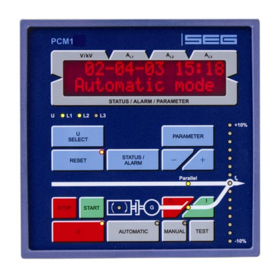
Display And Operating Elements The pressure-sensitive membrane of the front panel consists of a plastic coating. All keys have been designed as touch-sensitive membrane switch elements. The display is a LC display, comprising 2 ×16 characters, which are indirectly illuminated in red. The contrast of the display can be infinitely adjusted via a rotary poten- tiometer positioned on the left. -
Page 7: Brief Explanation Of The Leds And Push-Buttons
Brief Explanation Of The LEDs And Push-Buttons 2.1.1 LEDs No Description Function Voltage L1 Voltage L2 Voltage L3 Stop Mode "STOP" selected -10%..fn..+10% Synchroscope Automatic Mode "AUTOMATIC" selected Manual Mode ",MANUAL" selected Protection Monitoring is active Alarm Alarm message present ON (GCB ON) Reply: GCB is closed ON (MCB ON) -
Page 8: Functional Overview
Functional Overview Automatic mode Engine Setpoint Mode MANUAL " Start engine " Stop engine " close GCB " open GCB " [PCM1-M] close MCB " [PCM1-M] open MCB " raise setpoint value " lower setpoint value Mode AUTOMATIC and DI or operating "... -
Page 9: Leds
LEDs NOTE The LEDs can be checked via a lamp test. In order to achieve this, the " + " and " - " push-buttons must be pressed si- multaneously. UL1 - UL2 - UL3 Voltage control Color: green The LEDs "UL1", "UL2" and "UL3" show which voltage (U ) is currently being displayed. - Page 10 Manual Operating mode "MANUAL" Color: yellow If the "Manual" LED is lit, the "MANUAL" operating mode is active. The push- buttons for direct activation of the power circuit breaker and the start / stop push- buttons are active. Protection Engine monitoring Color: green If the "Monitoring"...
-
Page 11: Push-Buttons
Push-Buttons In order to facilitate the setting of the parameters the buttons are equipped with a "AUTOROLL-function". It al- lows to switch to the next setting and configuration screens, the digits, or the cursor position. The "AUTOROLL" function will only be enabled when the user depresses the corresponding keys for a certain period of time. 2.4.1 General/Configuration STATUS / ALARM... -
Page 12: Operation Of The Power Circuit Breakers
2.4.2 Operation Of The Power Circuit Breakers GCB ON / GCB OFF Close GCG / open GCB Color: green/red Note: Only enabled if operating mode MANUAL or TEST has been selected. GCB ON ..Depending on which power circuit breaker logic has been set, the GCB can be closed by pressing the "GCB ON"... -
Page 13: Operating Mode Select Switch
2.4.3 Operating Mode Select Switch AUTOMATIC Operating mode AUTOMATIC Color: gray The engine is automatically started and stopped, and the power circuit breakers are automatically actuated. The two control inputs "Automatic 1" and "Automatic 2" are used to specify various modes in "AUTOMATIC" operating mode (also see de- scription of control inputs). -
Page 14: Table 2.1: Function - External Operation Mode Selection
TEST Operating mode TEST Color: gray By actuating the "TEST" push-button, the engine is started, and engine monitoring is activated. No power circuit breakers are operated. This is carried out in the event of mains failure and when emergency power is switched on. Start of a load test A load test is enabled via the actuation of the "GCB ON"... -
Page 15: Lc Display
WARNING The engine may start unintentionally if an alarm, which caused the engine to shut down, is acknowledged and an enabling is still present. Before acknowledging the alarm, check the cause of the alarm, in order to protect operating personnel located in the vicinity of the system against injuries, and to protect the engine against unintentional destruc- tion. -
Page 16: Display
Display Measuring Values 3.1.1 First Display Line NOTE By using the button "U SELECT" the different voltages can be displayed. Display in automatic mode, first line: measuring value xxxx yyy yyy yyy ------------------------ The following measuring values are displayed (depending on the LEDs UL1/UL2/UL3): •... -
Page 17: Direction Of Power
3.1.2 Direction Of Power If the item's current transformers are wired according to the pin diagram shown, the following values are displayed: • Positive generator real power... The generator supplies real power. • Inductive gen. power factor ϕ ..The generator is overexcited and supplies inductive re-active power. •... -
Page 18: Second Display Line
3.1.3 Second Display Line NOTE The second line can be scrolled using the "STATUS / ALARM" push-button. It is also possible, to scroll through any alarms that may be present using the "STATUS / ALARM" push-button. These display screens are displayed in succession by pressing the "STATUS / ALARM" push-button. When the last display screen has been reached, the basic screen is displayed. - Page 19 Succession Display Description Actual value of the analog inputs (this display depends on the --- --- --- --- --- --- --- -- xxxxxxxxxxxxxxxx configuration of the analog input; P01) Generator re-active power (is determined via the current of --- --- --- --- --- --- --- -- phase L1;...
-
Page 20: Service Display
Service Display Service display ON/OFF Service display ON ....The following three screens are displayed (the voltages and frequencies of the busbar, the mains and the generator are displayed). In addition, the only visible, while configuration mode is active controller outputs and the switching states of the power circuit breakers dur- ing synchronization are displayed. -
Page 21: Status Of Power Circuit Breakers And Relays During Synchronization
3.2.3 Status Of Power Circuit Breakers And Relays During Synchronization Status of power circuit breakers and relays of the controllers Rel.: f U GCB The display shows the actual relay states of the controller outputs and the signals to the power circuit breakers during synchronization. -
Page 22: Operating Conditions
Operating Conditions Synchron. GCB Operating mode: GCB is synchronized (Synchronous generators) Synchron. GLS The GCB will be synchronized and will be closed when the synchronous condi- tions are met. Synchronization will be carried out, if generator voltage and busbar voltage are present. Synchron. - Page 23 Aux.serv.prerun Operating mode: Auxiliary operation Pre-run Vorl.Hilfsbetr. Before each starting procedure (except of an emergency operation) one of the re- lays keeps picked up as long as this message is monitored. With it external instal- lations can be prepared on the engine start (e.g. open sunblind, start cooling wa- ter pumps etc.).
- Page 24 NOTE The texts "Sprinkler operation", "Emergency power", "Test", "Load test" and "Sprinkler+Emergency power" are alternately displayed with the basic display screen. If one of these texts is active, the actuation of the "STATUS / ALARM" push- button switches to the continuous display of the basic display screen. This can be undone again by actuating the "RE- SET"...
-
Page 25: Counter
Counter 3.4.1 Reset Maintenance Call Reset maintenance call ------------------------ WARTUNG Following the maintenance interval (adjusted during configuration by the service staff) the alarm message shown on the left is output in the display. Additionally the LED "Alarm" flashes and the relay "Centralized alarm" (horn) picks up. To acknowledge this alarm message and to reset the service counter on the adjusted value, the following procedure applies: 1.) Acknowledge the horn message with a short pressure (short acknowledgement) on the... -
Page 26: Alarm Messages
Alarm Messages Alarm Classes NOTE Via the activation of "Sprinkler operation" (terminal 6), alarm classes F2 and F3 are converted to alarm class F1. Ex- ception: terminal 34 (or terminal 61, if terminal 34 is not available) and overspeed. Alarm class F2 and alarm class F3 ⇒ Alarm class F1 The monitoring functions are divided into four alarm classes: F0 - Warning alarm - - - - This alarm does not lead to an interruption of the operation. -
Page 27: Short Acknowledgement (< 2,5 S)
4.2.1 Short acknowledgement (< 2,5 s) Meaning • The "RESET" push-button is pressed for 0.5 s < t < 2.5 s or • the terminal 6 is set for 0.5 s < t < 2.5 s. Result • The LED "alarm" is continually illuminated. Acknowledgement via Operating mode Button "RESET"... -
Page 28: Alarm Messages
4.2.3 Alarm Messages NOTE The alarm messages can be scrolled in the second line using the "STATUS / ALARM" push-button. Display in automatic mode, second line: Alarms ------------------------ yyyyyyyyyyyyyyy If alarms occur, the corresponding alarm messages are displayed in the lower line of the LC display according to the following list: Type of alarm Alarm-... - Page 29 NOTE Discrete input – If a discrete input has been configured as alarm input, this will be displayed with its configured text in the display when triggered. Analog input – The text, assigned in the respective mask, is displayed as alarm message. An "!" appears in front of the configured text (for limit value 1 "Warning"...
- Page 30 Gen.overload Alarm message: Generator overload Alarm class: 3 Gen.-Überlast The limit values for monitoring the generator overload are exceeded for the period of delay time. Revers/min.power Alarm message: Generator reverse-/-reduced load Alarm class: 3 Rück/Minderleist The limit values for monitoring the generator reverse-/-reduced load are under- run/exceeded for the period of delay time.
- Page 31 MCB syn.failure Alarm message: Connect time MCB exceeded Alarm class: 1 Zuschaltzeit NLS If the connect time of the MCB is exceeded, this message is shown in the display. At the same time an alarm of alarm class F1 is output. EXT open failure Alarm message: Malfunction when opening an external breakerA Störung EXT AUF...
- Page 32 Service Alarm message: Maintenance call Alarm class: 1 Wartung ⇒ see also "Reset Maintenance Call" on page 25. Following the expiry of the maintenance interval, the imminence of the next main- tenance is displayed with this message. Not wanted stop Alarm message: Not wanted stop Alarm class: 3 ungewollter Stop...
- Page 33 TD_PCM1x_Packages_Function/Operation_08.04_GB...
- Page 34 Woodward SEG GmbH & Co. KG Krefelder Weg 47 ⋅ D – 47906 Kempen (Germany) Postfach 10 07 55 (P.O.Box) ⋅ D – 47884 Kempen (Germany) Phone: +49 (0) 21 52 145 1 Internet Homepage http://www.woodward-seg.com Documentation http://doc.seg-pp.com Sales Phone: +49 (0) 21 52 145 635 ⋅ Telefax: +49 (0) 21 52 145 354 e-mail: kemp.electronics@woodward.com...
Need help?
Do you have a question about the PCM1x and is the answer not in the manual?
Questions and answers