Sign In
Upload
Manuals
Brands
Woodward Manuals
Controller
Peak 200
Woodward Peak 200 Steam Turbine Control Manuals
Manuals and User Guides for Woodward Peak 200 Steam Turbine Control. We have
1
Woodward Peak 200 Steam Turbine Control manual available for free PDF download: Original Instructions Manual
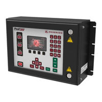
Woodward Peak 200 Original Instructions Manual (195 pages)
Digital Control for Steam Turbines
Brand:
Woodward
| Category:
Controller
| Size: 6.83 MB
Table of Contents
Table of Contents
3
Warnings and Notices
9
Electrostatic Discharge Awareness
11
Regulatory Compliance
12
Chapter 1. General Information
16
Introduction
16
Figure 1-1. Single Inlet Valve Steam Turbine
16
Controller Overview
17
Functional Block Diagrams
17
Figure 1-2. System Overview
17
Peak200 Keypad and Display
18
Figure 1-3. Peak200 Keypad and Display
18
Peak200 Functional Inputs and Outputs
19
Figure 1-4. Linknet HT Distributed I/O Node
23
Communications (to Plant Controls)
24
Chapter 2. Hardware Specification
25
Peak200 Description and Features
25
Figure 2-1. Functional Block Diagram (Peak200 Control)
25
Maintenance Info and Recommendations
26
Electromagnetic Compatibility (EMC)
27
Bulkhead Version Mounting Information
27
Figure 2-2. Peak200 Bulkhead Unit
28
Wiring Differences between Peak150 and Peak200
29
Figure 2-3. Peak200 Bulkhead Mount Version Outline Drawing
32
Panel Version Mounting Information
33
Figure 2-4. Peak200 Front Panel Mount Unit
33
Figure 2-5. Peak200 Front Panel Mount Version Outline Drawing
34
Input Power Specification
35
Communications (Ethernet)
36
Table 2-4. Ethernet Ports #1-2 (10/100)
37
Table 2-6. CAN Connector Pinout
38
Figure 2-6. COM1 Example RS-485 Wiring
39
Hardware - Terminal Blocks & Wiring
40
Figure 2-7. Peak200 Back Cover Label - Bulkhead
40
Figure 2-8. Peak200 Back Cover Label - Front Panel Mount
41
I/O Signal Specifications and Wiring
42
Figure 2-9. Terminal Block Connectors
42
Figure 2-10. Speed Sensor Block Diagram
43
Figure 2-11. Analog Input - Self-Powered Block Diagram
44
Figure 2-12. Analog Input - Loop-Powered Block Diagram
44
Figure 2-13. Analog Output Block Diagram
45
Figure 2-14. Actuator Output Block Diagram
46
Figure 2-15. Discrete Input Block Diagram
47
Troubleshooting Fault Codes
48
Troubleshooting & Commissioning Checks
48
Figure 2-16. Relay Output Block Diagram
48
Chapter 3. Control Description
51
Introduction
51
Front Panel View
51
Figure 3-1. Speed Relationships
51
Figure 3-2. Front Panel
51
Four Fixed Operational Action Buttons on Front Panel
52
User Login Levels
53
Figure 3-3. Mode Screen
53
Figure 3-4. Language
53
Navigation
54
Figure 3-5. Navigation Cross
54
Page Organization
55
Figure 3-6. Service Menu Showing "Speed Control" IN-Focus
55
Figure 3-7. Configuration Menu - Operation Mode (View Only)
55
Start Modes
56
Figure 3-8. Configuration Menu - Configuration Mode (Edit)
56
Figure 3-9. Startup Curve Screen
57
Operating Mode (Setting Turbine Speed)
58
Process/Cascade Control
59
Figure 3-10. Cascade Functional Diagram
59
Table 3-1. Cascade Control Status Messages
60
Chapter 4. Configuration Procedures
64
Program Architecture
64
Display Modes and User Levels
64
Mode Descriptions
65
User Level Descriptions
65
Figure 4-1. Initial HOME Screen (Unit Not Configured)
66
Using Configure Menus
67
Figure 4-2. Configuration Menu - Configuration Mode (Edit) with Error
68
Table 4-3. Peak150 to Peak200 Configuration Parameter Locations
69
Table 4-4. Analog Input Options
75
Table 4-5. Analog Readout Options
77
Table 4-6. Contact Input Options
78
Table 4-7. Options for Relays Ff Used to Indicate State
79
Table 4-9. LN Analog Input Function Options
81
Table 4-10. LN RTD Input Function Options
82
Table 4-11. LN Discrete Contact Input Options
83
Table 4-13. Options for Level Switch
84
Chapter 5. Operating Procedures
85
Software Architecture
85
Figure 5-1. Software Architecture
85
Front Panel Operation
86
Power-Up Screen
86
Figure 5-2. Peak200 Keypad with "Splash Screen
86
Figure 5-3. Boot-Up to HOME Screen (Remoteview)
87
Control Mode Architecture
88
Figure 5-4. Control Mode Architecture
88
Overview
89
Speed Control
89
Figure 5-5. Overview Screen
89
Figure 5-6. Speed Control Screen
89
Valve Demand
90
Controllers
90
Figure 5-7. Valve Demand Screen
90
Figure 5-8. Controllers Screen
90
Cascade Control
91
Analog Input
91
Figure 5-9. Cascade Control Screen
91
Contact Input Summary
92
Figure 5-10. Analog Input Summary Screen
92
Figure 5-11. Contact Input Summary Screen
92
Analog Output Channel
93
Relay Output Summary
93
Figure 5-12. Analog Output Channel Screen
93
Figure 5-13. Relay Output Summary Screen
93
Actuator Driver Summary
94
Overspeed Test Function (Speed Control Screen)
94
Figure 5-14. Actuator Driver Summary Screen
94
Figure 5-15. Overspeed Test Permissives
94
Figure 5-16. Internal (Peak200) Overspeed Test
95
Figure 5-17. External Overspeed Test
96
Alarm Summary
97
Figure 5-18. Alarm Summary Screen
97
Table 5-1. ALARM Messages
98
Shutdown Summary
100
Figure 5-19. Shutdown Summary Screen
101
Speed and Cascade Dynamics Adjustments
102
Figure 5-20. Speed Dynamics Adjustment Screen
102
Figure 5-21. Typical Response to Load Change
104
Starting Procedures (Start Curve Screen)
106
Figure 5-22. HOME Menu Showing "Startup Curve" IN-Focus
106
Critical Speed Band Avoidance
108
Speed Control
108
Speed Control Screen
109
Shutdown and Alarm Function Summary
110
Valve Ramp (Limiter) Control
110
Manual Valve Demand (Ramp) Control
111
Zero Speed Signal Override
111
Automatic Speed Override
111
Slow Roll down Failsafe Override
111
Actuator Calibration/Stroking Procedure
112
Chapter 6. Modbus Communications
113
Introduction
113
Modbus Wiring
113
Figure 6-1. Modbus Communication Connections
113
Basic Modbus Overview
114
Figure 6-2. Typical RS-232 Communications
114
Figure 6-3. Typical RS-485 Communications
114
Figure 6-4. Basic Modbus Overview
115
Table 6-3. Modbus Function Codes
116
Modbus Addresses
117
Figure 6-5. Modbus Messages
117
Table 6-5. Available Holding Coils
118
Table 6-7. Available Input Registers
120
Table 6-8. Available Holding Registers
122
Chapter 7. Service Menus
123
Introduction
123
Screen/Key Options Menu
123
Figure 7-1. Service Menu
123
Speed Control Menu
124
Valve Demand Menu
126
Real Time Clock Menu
126
Cascade Control Menu
127
Communications Menu
128
MPU Override Menu
128
Operation Log Menu
129
Chapter 8. Troubleshooting
130
General
130
User Level Password
130
Diagnostics
130
Troubleshooting Chart
131
Figure 8-1. GAP-To-GUI Communication Problem
131
Alarms / Shutdowns
135
Wiring / Component Problems
135
Actuators / Control Adjustments
135
Other Operating Problems
135
Chapter 9. Product Support and Service Options
136
Product Support Options
136
Product Service Options
136
Returning Equipment for Repair
137
Replacement Parts
138
Engineering Services
138
Contacting Woodward's Support Organization
138
Technical Assistance
139
Appendixa Configuration Mode Worksheets
140
Introduction
140
Appendixb Service Mode Worksheets
149
Appendixc Automatic Speed Pid Dynamic Analysis
152
Figure C-1. Speed PID Dynamic Optimizer
152
Figure C-2. Speed Vs Actuator Trends During Analysis
153
Figure C-3. Speed PID Optimizer Configuration
154
Appendix D Servlink-To OPC Server (SOS) Tool
161
SOS Communication Link
161
Installing SOS
161
Figure D-1. SOS
161
Connecting a Pc/Laptop to the Control
162
Figure D-2. SOS Install Window
162
Figure D-3. SOS Server Status Dialog Box
162
Figure D-4. SOS - New Session Box
163
Figure D-5. SOS - Enter Peak200 TCP/IP Address
163
Figure D-6. SOS - Active Links Dialog Box
163
Appendix E. Control Assistant-Software Interface Tool
164
Features of Control Assistant
164
Installing Control Assistant
164
Figure E-1. Control Assistant License Agreement
164
Figure E-2. Control Assistant Install Window
165
Figure E-3. Control Assistant Folder Selection
165
Figure E-4. Control Assistant Install Complete
165
Using Control Assistant
166
Figure E-5. Install Restart Window
166
Figure E-6. Control Assistant Window
166
Figure E-7. Dialog for Servlink OPC Connection
167
Figure E-8. Winpanel Session
167
Figure E-9. Control Assistant - Retrieve Tunable Dialog Box
168
Figure E-10. Control Assistant - Send Tunable Dialog Box
169
Figure E-11. Control Assistant - Speed Control Trend Script
170
Figure E-12. Control Assistant - Create Trend Script File
170
Appendix F. Appmanager Service Tool
171
File Management with App. Manager
171
Installing App Manager
171
Figure F-1. App Manager Install Window
171
Figure F-2. App Manager License Agreement Window
172
Figure F-3. App Manager Installation
172
Figure F-4. App Manager Install Complete
173
Figure F-5. Appmanager Window
173
Figure F-6. Dialog for App Manager Connection
174
Figure F-7. App Manager Connected to a Control
174
Figure F-8. Appmanager Control Info Window
175
Figure F-9. Appmanager Control (GAP) Application Panel
175
Figure F-10. Appmanager GUI Application Panel
176
Figure F-11. Retrieving Files
176
Appendix G. Using Peak200 Internal Simulation Mode
178
Figure G-1. HW Simulation Mode Access
178
Table G-1. Example Demo Configuration Settings
179
Appendix H. Startup and Commissioning Checklist
181
Appendix I. Feature Pack (FP) S/W Add-Ons for Peak200
183
Updating the Application Software
183
Activating a Feature Pack
184
Figure I-1. HOME Page
184
Contents of Feature Pack 1 (License P/N: 8447-5004 - Release Aug/2017)
185
Figure I-2: Site Info Page
185
Figure I-3: Site Key Pop-Up Page
185
Adding Linknet Distributed I/O
186
Figure I-4. Additional Control I/O
186
Datalogging
187
Figure I-5. Datalog Feature Screens
187
Figure I-6. Selecting Datalog Trend Parameters
188
Figure I-7. Appmanager Setup for Automatic Collection of Datalog Files
189
Multi-Lingual Support
190
Event History Access
190
Figure I-8. Language Icon on Mode Screen
190
Figure I-9. Navigation to Event History Page
190
Start Permissive Discrete Input
191
Figure I-10: Start Pop-Up Page with Start Permissive
191
Figure I-11: Menu Selections for DI and Relay Output
191
Revision History
192
Declarations
193
Advertisement
Advertisement
Related Products
Woodward PG200
Woodward PGG-EG 200
Woodward ProAct Digital Plus
Woodward ProAct IV
Woodward PCM1x
Woodward PCM1-G
Woodward ProAct ITB
Woodward PCM1-M
Woodward PCL1
Woodward ProAct III
Woodward Categories
Controller
Control Unit
Relays
Control Systems
Industrial Equipment
More Woodward Manuals
Login
Sign In
OR
Sign in with Facebook
Sign in with Google
Upload manual
Upload from disk
Upload from URL