Woodward DTSC-200 Operation Manual
Ats controller
Hide thumbs
Also See for DTSC-200:
- Configuration manual (158 pages) ,
- Manual (141 pages) ,
- Installation manual (41 pages)
Table of Contents
Advertisement
Advertisement
Table of Contents

Subscribe to Our Youtube Channel
Related Manuals for Woodward DTSC-200


Summary of Contents for Woodward DTSC-200
- Page 1 37387A DTSC-200 ATS Controller Operation Software Version 1.0006 Manual 37387A...
- Page 2 Provides other helpful information that does not fall under the warning or caution categories. Woodward reserves the right to update any portion of this publication at any time. Information provided by Woodward is believed to be correct and reliable. However, Woodward assumes no responsibility unless otherwise expressly undertaken.
-
Page 3: Table Of Contents
Manual 37387A DTSC-200 - ATS Controller Revision History Rev. Date Editor Changes NEW 07-12-12 Release 08-11-25 Implementation of the changes starting with SW version 1.0006 Content 1. G ..................5 HAPTER ENERAL NFORMATION Related Documents ..........................5 2. N .................. - Page 4 Manual 37387A DTSC-200 - ATS Controller Illustrations And Tables Illustrations Figure 2-1: Front panel and display ............................6 Figure 2-2: Screen - Level overview ............................12 Figure 3-1: General ATS functionality - flowchart ........................16 Figure 3-2: Limit switch monitoring - failure message ......................19 Tables ...
-
Page 5: Chapter 1. General Information
Manual 37387A DTSC-200 - ATS Controller Chapter 1. General Information Related Documents ≡≡≡≡≡≡≡≡≡≡≡≡≡≡≡≡≡≡≡≡≡≡≡≡≡ Type English German DTSC-200 Series DTSC-200 - Installation 37385 DTSC-200 - Configuration 37386 DTSC-200 - Operation this manual 37387 DTSC-200 - Application 37388 DTSC-200 - Interfaces 37389... -
Page 6: Chapter 2. Navigation / Operation
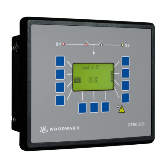
Manual 37387A DTSC-200 - ATS Controller Chapter 2. Navigation / Operation DTSC-200 Figure 2-1: Front panel and display Figure 2-1 illustrates the front panel/display, which includes push buttons, LEDs and the Liquid Crystal display (LC display). A short description of the front panel is given below. -
Page 7: Navigation
Manual 37387A DTSC-200 - ATS Controller Navigation ≡≡≡≡≡≡≡≡≡≡≡≡≡≡≡≡≡≡≡≡≡≡≡≡≡ Individual display screens are listed in the following text. All softkeys, which are available in the individual screens are described with their function. Screen "Automatic operation" / "Start screen" [all application modes] This screen appears upon startup of the unit. - Page 8 Manual 37387A DTSC-200 - ATS Controller Screen "Source 2 values - Details" [all application modes] This screen appears after pressing the softkey again. All measured source 2 values are displayed in this screen. Navigate to the next screen Navigate to the previous screen...
- Page 9 Manual 37387A DTSC-200 - ATS Controller Screen "S2 Load Current" [all application modes] This screen appears after pressing the softkey again. The slave pointers show the maximum currents monitored by the control unit. Navigate to the next screen Navigate to the previous screen...
- Page 10 Manual 37387A DTSC-200 - ATS Controller Screen "Time / Date" [all application modes] This screen appears after pressing the softkey again. Here the time and date are displayed. Navigate to the next screen Navigate to the previous screen Return to the start screen...
- Page 11 Manual 37387A DTSC-200 - ATS Controller Screen "Alarm list" [all application modes] This screen appears after pressing the softkey in the start screen. All alarm messages, which have not been acknowledged and cleared, are dis- played. Each alarm is displayed in two lines; the first line describes the alarm message and the second line is the date and time of the alarm oc- curred in the format Mon-dd hh:mm:ss.ss.
-
Page 12: Operation
Manual 37387A DTSC-200 - ATS Controller Operation ≡≡≡≡≡≡≡≡≡≡≡≡≡≡≡≡≡≡≡≡≡≡≡≡≡ The display is partitioned into different areas to give an overview of the displayed data. Softkeys Messages Timer Operation Softkeys Figure 2-2: Screen - Level overview "Operation" The "Operation" section of the screen shows the current status of the sources. -
Page 13: Operation Display
Manual 37387A DTSC-200 - ATS Controller Operation Display "Operation" display The current operation state of the unit and the condition of the sources are displayed during normal operation. Operation state The current operation state of the unit is indicated in the "Messages" section of the screen. -
Page 14: Navigation
Manual 37387A DTSC-200 - ATS Controller Navigation Softkeys "Navigation" For navigation between the main screens the softkeys dis- played in the right section are used. The softkeys are assigned with different functions. Read alarm list If alarms have occurred during operation this softkey character appears. By pressing this softkey the alarm list is displayed. -
Page 15: Logicsmanager
Manual 37387A DTSC-200 - ATS Controller LogicsManager Some parameters of the DTSC-200 are configured via the (refer to Configuration Manual LogicsManager 37386). A typical screen is shown in the following. You may configure a logical operation using LogicsManager various command variables, signs, and logical operators to achieve the desired logical output. -
Page 16: Chapter 3. Functional Description
Manual 37387A DTSC-200 - ATS Controller Chapter 3. Functional Description General ATS Functionality ≡≡≡≡≡≡≡≡≡≡≡≡≡≡≡≡≡≡≡≡≡≡≡≡≡ The following flowchart shows the typical ATS functionality: Source 1 is Source 2 is powering the load available Close breaker to Source 1 Source 1 available ? -
Page 17: Application Modes
Manual 37387A DTSC-200 - ATS Controller Application Modes ≡≡≡≡≡≡≡≡≡≡≡≡≡≡≡≡≡≡≡≡≡≡≡≡≡ The application mode may be configured in the unit (refer to the Configuration Manual 37386 for more informa- tion). This is only possible in code level 2. The most important features and differences of the three application modes are illustrated in the following section. -
Page 18: Blocking Transfer Operations
Manual 37387A DTSC-200 - ATS Controller Blocking Transfer Operations ≡≡≡≡≡≡≡≡≡≡≡≡≡≡≡≡≡≡≡≡≡≡≡≡≡ The following conditions result in blocking all transfer operations. This means that the flags LogicsManager • 20.07 "Close to S1" • 20.09 "Close to S2" • 20.08 "Open from S1"... -
Page 19: Mechanical Failure (Limit Switch Monitoring)
(C2, C1, C2O, C1O) is cur- rently being issued by the ATS controller. The DTSC-200 evaluates the currently present replies from the ATS limit switch together with the currently available source to determine which reply signals are currently expected to be able to supply the load. -
Page 20: Table 3-1: Limit Switch Monitoring - Truth Table For "Standard" Limit Switch W/O "Open" Replies
Manual 37387A DTSC-200 - ATS Controller Truth Tables The truth tables indicate all possible reply signal combination conditions and the respective reactions of the ATS controller depending on the configuration of the parameters 3424 "Transfer switch type" and 3434 "Use limit sw. -
Page 21: Table 3-2: Limit Switch Monitoring - Truth Table For "Delayed" Limit Switch W/O "Open" Replies
Manual 37387A DTSC-200 - ATS Controller Table 3-2 is valid for the following settings: • Parameter 3424 "Transfer switch type" is configured to "Delayed" • Parameter 3434 "Use limit sw. OPEN replies" is configured to "NO" S1 preferred S1 source OK S2 source OK S1 closed signal S2 closed signal Actual... - Page 22 Manual 37387A DTSC-200 - ATS Controller S1 preferred S1 OK S2 OK S1 closed signal S2 closed signal S1 open signal S2 open signal Actual Expected ----- S2 S1O S2 S1O S2 S1O S2 S1O S2 S2O S2 S1O S2 S1O S2O...
-
Page 23: Table 3-3: Limit Switch Monitoring - Truth Table For "Open" Limit Switch With "Open" Replies
Manual 37387A DTSC-200 - ATS Controller S1 preferred S1 OK S2 OK S1 closed signal S2 closed signal S1 open signal S2 open signal Actual Expected S2 S1O S2 S2O S2 S1O S2 S1O S2O S2 S1O S2 S1O S1 S1O... -
Page 24: Chapter 4. Configuration
Manual 37387A DTSC-200 - ATS Controller Chapter 4. Configuration This chapter provides information "how to configure the unit via the LC display" as well as the description of all parameters that may be changed without a password. If you have the correct passwords to access all code levels in order configure the unit, refer to manual 37386 for a description of all parameters, their setting range, and their influence to the operation of the unit. - Page 25 Manual 37387A DTSC-200 - ATS Controller Access configuration menus By pressing the softkey, the main menu will be displayed to permit configuration of the control unit. Softkeys "Configuration - select parameter" Navigation through the parameters is carried out using the soft- keys and .
-
Page 26: Parameters
Manual 37387A DTSC-200 - ATS Controller Parameters ≡≡≡≡≡≡≡≡≡≡≡≡≡≡≡≡≡≡≡≡≡≡≡≡≡ NOTE A description of all parameters, which may be edited/configured via the display, are described in ma- nual 37386. Language Language Change language {Language} Language {Language} . The selection of a language will affect the following text in the control unit: •... -
Page 27: Code Levels
Manual 37387A DTSC-200 - ATS Controller Code Levels Code level display Code level via display Info Codeebene Display This value displays the code level that is currently active for access via the front panel. Code level CAN port Password CAN-Bus Info Codeebene CAN Schnittstel. -
Page 28: Real-Time Clock - Time
Manual 37387A DTSC-200 - ATS Controller Real-Time Clock - Time Hour Adjust clock time: hour 0 to 23 Stunden The hour of the current time is set here. Example: 0 ....0 hour of the day. 23 ....23 hour of the day. -
Page 29: Appendix A. Messages
Manual 37387A DTSC-200 - ATS Controller Appendix A. Messages Timer / Operation States ≡≡≡≡≡≡≡≡≡≡≡≡≡≡≡≡≡≡≡≡≡≡≡≡≡ The following table indicates the display messages of the various timers and operations states: Display text Description Corresponding timer parameter Note S1 Start delay Source 2 has failed, and now the S1 start delay timer is "S1 start delay time"... -
Page 30: Table 4-1: Timer / Operation States - Display
Manual 37387A DTSC-200 - ATS Controller Display text Description Corresponding timer parameter Note Inhib. XFR to S2 A transfer to Source 2 is inhibited although Source 2 is "Inhibit transfer to Source 2" available. In the case of an Source 1 failure, a transfer to activation via "Inhib. -
Page 31: Alarm Messages
Manual 37387A DTSC-200 - ATS Controller Alarm Messages ≡≡≡≡≡≡≡≡≡≡≡≡≡≡≡≡≡≡≡≡≡≡≡≡≡ Message in LeoPC1 Meaning Message in the display Batt.overvolt. Lev.1 Battery overvoltage, limit value 1 The battery voltage has exceeded the limit value 1 for battery overvoltage for at least the configured Batt.overvolt.1... - Page 32 Manual 37387A DTSC-200 - ATS Controller Message in LeoPC1 Meaning Message in the display In-phase timeout Inphase timer has expired If inphase monitoring is enabled and the unit was not able to detect a synchronicity between source 1 and source 2 within the configured time, this message will be displayed.
- Page 33 Phone +49 (0) 711 789 54-0 • Fax +49 (0) 711 789 54-100 stgt-info@woodward.com Homepage http://www.woodward.com/power Woodward has company-owned plants, subsidiaries, and branches, as well as authorized distributors and other authorized service and sales facilities throughout the world. Complete address/phone/fax/e-mail information for all locations is available on our website (www.woodward.com).
Need help?
Do you have a question about the DTSC-200 and is the answer not in the manual?
Questions and answers