Table of Contents
Advertisement
Quick Links
RTD Input Specifications
Inputs Channels
Data Format
Max. Common Mode Voltage
Common Mode Rejection
Absolute Maximum Ratings
Internal Resolution
RTD Input Ranges
RTD Linearization
Excitation Current (all ranges)
Accuracy vs. Temperature
Warm-up Time
Maximum Inaccuracy*
Sample Duration
(Single channel update rate)
Filter Characteristics
All Channel Update Rate
Open Circuit Detection Time
Conversion Method
External DC Power Required
*NOTE: Excluding RTD error, including temperature drift
Sales 800-633-0405
4 Differential
Floating Point
5VDC
-100dB min. @ DC, -100db min. @ 50/60 Hz*
Fault Protected Inputs to ±50V
16-bit, ±0.1°C or °F
Pt100
-200°C/850°C (-328°F/1562°F)
Pt1000
-200°C/595°C (-328°F/1103°F)
JPt100
-100°C/450°C (-148°F/842°F)
10: Cu.
-200°C/260°C (-328°F/500°F)
25: Cu.
-200°C/260°C (-328°F/500°F)
120: Ni.
-80°C/260°C (-112°F/500°F)
Automatic
210µA
±10ppm per °C (maximum)
2 minutes for ±0.2% repeatability
±1°C maximum @ 16.7 Hz
±3°C maximum @ 470Hz
±5°C maximum on Cu10 & Cu25
Dependent on digital filter settings-
200ms @ 16.7 Hz, 90ms @ 470Hz
Digital Filter cutoff frequencies:
16.7 Hz, 470Hz
Single channel update rate times the number of
enabled channels
Burnout detect within 2s
Sigma-Delta
None
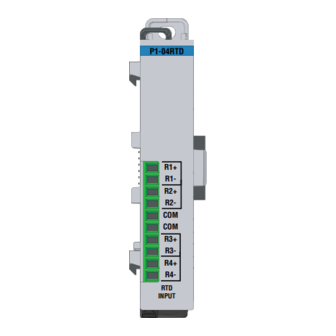
P1-04RTD Analog Input
P1-04RTD
The P1-04RTD Input Module provides four differential
channels for receiving RTD and resistance input
signals for use with the Productivity1000 system.
RTD Input Specifications . . . . . . . . . . . . . . . . . . . . . 1
General Specifications . . . . . . . . . . . . . . . . . . . . . . 2
Removable Terminal Block Specifications. . . . . . . . 2
Wiring Diagram and Schematic . . . . . . . . . . . . . . . . 3
Module Installation Procedure . . . . . . . . . . . . . . . . . 4
R1+
QR Code . . . . . . . . . . . . . . . . . . . . . . . . . . . . . . . . . 4
Wiring Options . . . . . . . . . . . . . . . . . . . . . . . . . . . . . 5
R1-
Module Configuration . . . . . . . . . . . . . . . . . . . . . . . 5
R2+
Resistance Input Specifications . . . . . . . . . . . . . . . 6
Diagnostics . . . . . . . . . . . . . . . . . . . . . . . . . . . . . . . 6
R2-
Typical Application Example . . . . . . . . . . . . . . . . . . 7
Warning . . . . . . . . . . . . . . . . . . . . . . . . . . . . . . . . . . 8
COM
R3+
R3-
R4+
R4-
RTD
INPUT
Warranty: Thirty-day money-back guarantee. Two-year limited
replacement (See www.productivity1000.com for details).
www.productivity1000.com
1000
1
Advertisement
Table of Contents

Subscribe to Our Youtube Channel
Related Manuals for Automationdirect.com Productivity 1000 P1-04RTD


Summary of Contents for Automationdirect.com Productivity 1000 P1-04RTD
- Page 1 RTD Input Specifications Inputs Channels 4 Differential 1000 Data Format Floating Point Max. Common Mode Voltage 5VDC Common Mode Rejection P1-04RTD Analog Input -100dB min. @ DC, -100db min. @ 50/60 Hz* Absolute Maximum Ratings Fault Protected Inputs to ±50V P1-04RTD Internal Resolution 16-bit, ±0.1°C or °F...
- Page 2 General Specifications Terminal Block Specifications Operating Temperature 0º to 60ºC (32º to 140ºF) Part Number P1-10RTB P1-10RTB-1 Storage Temperature -20º to 70ºC (-4º to 158ºF) Positions 10 Screw Terminals 10 Spring Clamp Terminals Humidity 5 to 95% (non-condensing) 30–16 AWG (0.051–1.31 mm²) 28–16 AWG (0.081–1.31 mm²) Solid / Stranded Conductor Solid / Stranded Conductor...
- Page 3 P1-04RTD Schematic P1-04RTD Wiring Diagram Resistance Input RTD Input Circuits 2-wire RTD INTERNAL MODULE CIRCUITRY CH1 RTD Note: Connect two wires to one side of a two-wire RTD. INPUT 1. R+, R-, and COM wires to an 2. For 2-wire RTD, attach a third wire to RTD must be equal length and module common.
- Page 4 Module Installation QR Code WARNING: Do not add or remove modules with field power applied. Step One: With latch in “locked” position, align P1-08TD1 P1-08TD1 connectors on the side of each module and stack by pressing together. Click indicates lock is engaged.
- Page 5 Module Configuration Wiring Options Screw Terminal Block (included) P1-10RTB (Quantity 1) Using the Hardware Configuration tool in the Spring Clamp Terminal Block Productivity Suite programming software, drag and drop P1-10RTB-1 the P1-04RTD module into the base configuration. Specify Temperature Scale and Burnout Detection, and (Quantity 1) use the drop down menu to select module range and resolution.
- Page 6 Resistance Input Specifications Internal Resolution 16-bit, 0.0015% of full scale range in ohms 0 – 10,000 : Resolution 1: 0 – 6,250 : Resolution 0.1 : 0 – 3,125 : Resolution 0.1 : Resistance Input Ranges 0 – 1,562.5 : Resolution 0.1 : and Resolution 0 –...
- Page 7 Typical Application Example User’s Desired Setpoint Output Heat Controller Heater Process P1-04RTD Variable Oven Resistance (feedback) Temperature Temperature Device to P1-04RTD P1-04RTD Module INPUT Sales 800-633-0405 www.productivity1000.com...
- Page 8 This publication may also discuss features that may not be available in certain revisions of the product. Document Name Edition/Revision Date P1-04RTD-DS 1st Edition, Rev A 6/26/2018 Copyright 2018, AutomationDirect.com Incorporated/All Rights Reserved Worldwide www.productivity1000.com www.productivity1000.com Tech Support 770-844-4200 Tech Support 770-844-4200...
Need help?
Do you have a question about the Productivity 1000 P1-04RTD and is the answer not in the manual?
Questions and answers