Table of Contents
Advertisement
Quick Links
General Specifications
Operating Temperature
Storage Temperature
Humidity
Environmental Air
Vibration
Shock
Field to Logic Side
Isolation
Insulation Resistance
Heat Dissipation
Enclosure Type
Module Location
Field Wiring
EU Directive
Terminal Type
(sold separately)
Weight
Agency Approvals
*See CE Declaration of Conformance for details.
Sales 800-633-0405
0º to 60ºC (32º to 140ºF)
-20º to 70ºC (-4º to 158ºF)
5 to 95% (non-condensing)
No corrosive gases permitted
IEC60068-2-6 (Test Fc)
IEC60068-2-27 (Test Ea)
1800VAC applied for 1 second
> 10M: @ 500VDC
1950mW
Open Equipment
Any I/O position in a Productivity1000 System
Removable terminal block (sold separately). Use
ZIPLink Wiring System optional See "Wiring
Options" on page 5.
See the "EU Directive" topic in the Productivity
Suite Help File. Information can also be obtained at:
www.productivity1000.com
10-position Removable Terminal Block
60g (2.1 oz)
UL 61010-1 and UL 61010-2-201 File E139594,
Canada and USA
CE (EN 61131-2 EMC, EN 61010-1 and EN 61010-
2-201 Safety)*
P1-4ADL2DAL-2 Analog Input/
Output
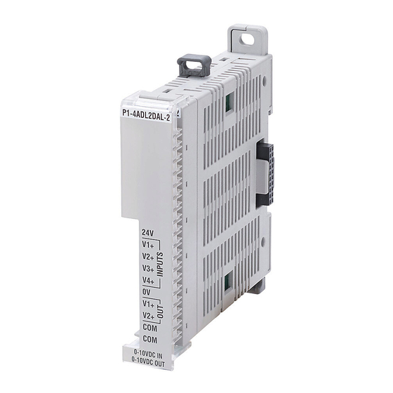
P1-4ADL2DAL-2
The P1-4ADL2DAL-2 Voltage Analog Input/Output
Module provides four 13 bit input channels at 0-10
VDC and two 12 bit output channels at 0-10VDC for
use with the Productivity1000 system.
General Specifications . . . . . . . . . . . . . . . . . . . . . . 1
Input Specifications . . . . . . . . . . . . . . . . . . . . . . . . . 2
Output Specifications . . . . . . . . . . . . . . . . . . . . . . . 2
Wiring Diagram and Schematic . . . . . . . . . . . . . . . . 3
Module Installation Procedure . . . . . . . . . . . . . . . . . 4
24V
QR Code . . . . . . . . . . . . . . . . . . . . . . . . . . . . . . . . . 4
Wiring Options . . . . . . . . . . . . . . . . . . . . . . . . . . . . . 5
V1+
Module Configuration . . . . . . . . . . . . . . . . . . . . . . . 5
V2+
Linear Scaling . . . . . . . . . . . . . . . . . . . . . . . . . . . . . 6
Non-Linear Scaling . . . . . . . . . . . . . . . . . . . . . . . . . 6
V3+
Warning . . . . . . . . . . . . . . . . . . . . . . . . . . . . . . . . . . 8
Terminal Block Specifications . . . . . . . . . . . . . . . . . 8
V4+
0V
V1+
V2+
COM
COM
0-10VDC IN
Terminal Block sold separately, (see wiring options on page 5).
0-10VDC OUT
Warranty: Thirty-day money-back guarantee. Two-year limited
replacement. (See www.productivity1000.com for details).
www.productivity1000.com
1000
1
Advertisement
Table of Contents

Related Manuals for Automationdirect.com Productivity 1000 P1-4ADL2DAL-2


Summary of Contents for Automationdirect.com Productivity 1000 P1-4ADL2DAL-2
-
Page 1: Table Of Contents
General Specifications Operating Temperature 0º to 60ºC (32º to 140ºF) 1000 Storage Temperature -20º to 70ºC (-4º to 158ºF) Humidity 5 to 95% (non-condensing) Environmental Air P1-4ADL2DAL-2 Analog Input/ No corrosive gases permitted Vibration IEC60068-2-6 (Test Fc) Output P1-4ADL2DAL-2 Shock IEC60068-2-27 (Test Ea) The P1-4ADL2DAL-2 Voltage Analog Input/Output Field to Logic Side... -
Page 2: Input Specifications
Input Specifications Output Specifications Outputs per Module Inputs per Module Output Range 0–10 VDC Input Range 0–10 VDC Signal Resolution 12-bit Signal Resolution 13-bit Resolution Value of LSB 0–10 VDC = 2.44 mV / count Resolution Value of LSB 0–10 VDC = 1.22 mV per count (least significant bit) 1 LSB = 1 count (least significant bit) -
Page 3: Wiring Diagram And Schematic
P1-4ADL2DAL-2 Schematic P1-04ADL2DAL-2 Wiring Diagram Voltage Input Circuits INTERNAL MODULE CIRCUITRY 4-Wire Voltage Transmitter ISOLATED ANALOG CIRCUIT POWER Transmitter AC or DC CH1 ADC Power Supply CH2 ADC 4-Wire Transmitter CH3 ADC CH4 ADC 3-Wire Voltage – Transmitter Voltage Source 24VDC User CH1 DAC Supplied... -
Page 4: Module Installation Procedure
Module Installation QR Code WARNING: Do not add or remove modules with field power applied. Step One: With latch in “locked” position, align P1-08TD1 P1-08TD1 connectors on the side of each module and stack by pressing together. Click indicates lock is engaged. -
Page 5: Wiring Options
Module Configuration Wiring Options ZIPLink Feed Through Modules and Cables¹ ZL-RTB20 ZL-RTB20-1 Using the Hardware Configuration tool in the Productivity Suite programming software, drag ZL-RTB20-1 and drop the P1-4ADL2DAL-2 module into the ZL-RTB20 0.5 m (1.6 ft) cable ZL-P1-CBL10 configuration. 1.0 m (3.3 ft) cable If desired, assign a User Tagname to each ZL-P1-CBL10-1... -
Page 6: Linear Scaling
Linear Scaling Non-Linear Scaling The Scale (Linear) function can be used to: Non-Linear Scalin • Convert analog field input signals from the range which is native to the The Scale (Non-Linear) function can be used for Non-Linear applications. analog input module to an application specific range. •... - Page 7 Sales 800-633-0405 www.productivity1000.com...
-
Page 8: Warning
0.1 in (2.5 mm) Maximum* Screw Size Screw Torque 2.5 lb·in (0.28 N·m) *Recommended Screw Driver TW-SD-MSL-1 Document Name Edition/Revision Date P1-4ADL2DAL-2-DS 2nd Edition 9/19/2019 Copyright 2019, AutomationDirect.com Incorporated/All Rights Reserved Worldwide www.productivity1000.com www.productivity1000.com Tech Support 770-844-4200 Tech Support 770-844-4200...
Need help?
Do you have a question about the Productivity 1000 P1-4ADL2DAL-2 and is the answer not in the manual?
Questions and answers