Table of Contents
Advertisement
Quick Links
Confidentiality Notice
This manual is provided solely as an operational, installation, and maintenance guide and contains
sensitive business and technical information that is confidential and proprietary to GAI-Tronics.
GAI-Tronics retains all intellectual property and other rights in or to the information contained herein,
and such information may only be used in connection with the operation of your GAI-Tronics product or
system. This manual may not be disclosed in any form, in whole or in part, directly or indirectly, to any
third party.
General Information
GAI-Tronics Corporation offers intrinsically-safe (I.S.) telephones and isolation barrier units (IBU),
which conform to all pertinent requirements in the USA and Canada. For convenience, a telephone and
an IBU can be purchased together under a single model number: Model 261-001 for indoor use, and
Model 271-001 for outdoors.
However, for rack-mount configurations or special applications, the telephones and IBUs can be
purchased separately:
•
Model 262-001 Indoor I.S. Phone
•
Model 272-001 Outdoor I.S. Phone
•
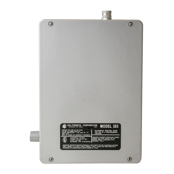
Model 263 Isolation Barrier Unit
The I.S. telephones are designed to be installed in all hazardous areas. The IBU or rack-mount card unit
is placed in a non-hazardous area up to one mile from the phone, limiting the energy levels going to the
hazardous area to conform to intrinsically-safe requirements.
The Model 263 Isolation Barrier Unit is constructed of durable glass-reinforced polyester, which is highly
resistant to chemicals and weather, and is rated Type 3R (rainproof).
GAI-TRONICS 3030 KUTZTOWN RD. READING, PA 19605 USA
610-777-1374
V
ISIT WWW
G A I - T R O N I C S ®
A H U B B E L L C O M P A N Y
Model 263
Isolation Barrier Unit
800-492-1212
.
-
.
GAI
TRONICS
COM FOR PRODUCT LITERATURE AND MANUALS
Fax: 610-796-5954
Pub. 42004-178D
Advertisement
Table of Contents

Related Manuals for GAI-Tronics 263


Summary of Contents for GAI-Tronics 263
-
Page 1: General Information
GAI-Tronics retains all intellectual property and other rights in or to the information contained herein, and such information may only be used in connection with the operation of your GAI-Tronics product or system. This manual may not be disclosed in any form, in whole or in part, directly or indirectly, to any third party. -
Page 2: Installation Of The Ibu
GAI-Tronics Pub. 42004-380, Control Drawing 73242. It must be installed in a non-hazardous location. See Figure 1 for a typical installation. The Model 263 Isolation Barrier Unit interior includes a power switch selector, a ring pitch adjustment, and four troubleshooting LEDs. The IBU housing is composed of two modular subassemblies, the front panel and the rear enclosure assembly, for easy installation and wiring. -
Page 3: Wiring Requirements
I.S. ground and connected only at the IBU. Wiring Guidelines/Control Drawing The Model 263 provides an intrinsically-safe circuit when installed in accordance with GAI-Tronics Pub. 42004-380, Control Drawing 73242. In addition, the NEC and the CEC provide additional installation details that are recommended for safe installation. -
Page 4: System Setup
Page: 4 of 13 System Setup GAI-Tronics recommends taking the following steps to ensure a safe and trouble-free installation: 1. Install the Model 263 Isolation Barrier Unit (IBU) and wire it completely, except for the hazardous area signal wires. WARNING The unit must be wired in accordance with Pub. - Page 5 Pub. 42004-178D Model 263 Isolation Barrier Unit (IBU) Page: 5 of 13 Figure 2. Rear of IBU enclosure with cover removed \\s_eng\gtcproddocs\standard ioms - current release\42004 instr. manuals\42004-178d.doc 03/06...
- Page 6 Pub. 42004-178D Model 263 Isolation Barrier Unit (IBU) Page: 6 of 13 Mounting 1. Remove the front panel by loosening the four front captive screws. 2. Refer to Figure 3. Determine which of the conduit locations is to be used. Drill spots have been provided for use with a chassis punch or hole saw.
-
Page 7: Operation
Model 263 Isolation Barrier Unit (IBU) Page: 7 of 13 Figure 3. Model 263 Isolation Barrier Unit dimensions Operation The Model 263 Isolation Barrier Unit requires no operator intervention for routine functions. \\s_eng\gtcproddocs\standard ioms - current release\42004 instr. manuals\42004-178d.doc 03/06... -
Page 8: Maintenance
Troubleshooting : It may be advantageous to temporarily connect an I.S. telephone panel directly to the output terminals of the Model 263 IBU when troubleshooting. Then, using the charts below, the cause of the problem should be more easily determined. -
Page 9: Equipment-Related Problems
Any field repairs on the intrinsically-safe design of the phone are strictly prohibited. Any such change will void ALL hazardous approvals. Please contact the GAI-Tronics Field Service Department at 800-492-1212 inside the USA or 610-777-1374 outside the USA for the Regional Service Center closest to you. -
Page 10: Lightning Protection
Pub. 42004-178D Model 263 Isolation Barrier Unit (IBU) Page: 10 of 13 Lightning Protection Telephone lines are susceptible to lightning strikes and must be properly protected and maintained. On- premise line protection is usually provided at the building entrance by the responsible telephone company when it is installed. -
Page 11: Specifications
Model 263 Isolation Barrier Unit (IBU) Page: 11 of 13 Specifications General/Environmental Location (Model 263 IBU) ............Ordinary (non-classified) indoor/outdoor FCC Registration Number ..................ADGUSA-65066-TE-E Ringer Equivalence Number (REN)....................0.4B IC Certification Number (Canada) ..................822 4541 A Load number (LN) (Canada)......................... 14 Connecting method (Canada)...................... - Page 12 Pub. 42004-178D Model 263 Isolation Barrier Unit (IBU) Page: 12 of 13 Model 263 Isolation Barrier Unit Electrical /Acoustical Telephone Network Interface....(2-wire)........BELL Pub. 61100 Compatible (4-wire)............See 4-wire option AC power input ........Voltage (selectable) ............. 90-132 V 180-240 V Frequency ........................
- Page 13 Pub. 42004-178D Model 263 Isolation Barrier Unit (IBU) Page: 13 of 13 Model 262-001 Indoor /Model 272-001 Outdoor I.S. Telephones Electrical /Acoustical Electrical specifications (nominal) ..................12 V, 12 mA Ringer performance (typical) ................... 98 dB @ 10 feet Frequency (adjustable at the IBU) ............1 kHz to 8 kHz (typical) Ring signal loss (18 AWG) ..................
-
Page 14: Warranty
Warranty Equipment. GAI-Tronics warrants for a period of one (1) year from the date of shipment, that any GAI-Tronics equipment supplied hereunder shall be free of defects in material and workmanship, shall comply with the then-current product specifications and product literature, and if applicable, shall be fit for the purpose specified in the agreed-upon quotation or proposal document.
Need help?
Do you have a question about the 263 and is the answer not in the manual?
Questions and answers