Table of Contents
Advertisement
Pub. 43004-008H
G A I - T R O N I C S ® C O R P O R A T I O N
A H U B B E L L C O M P A N Y
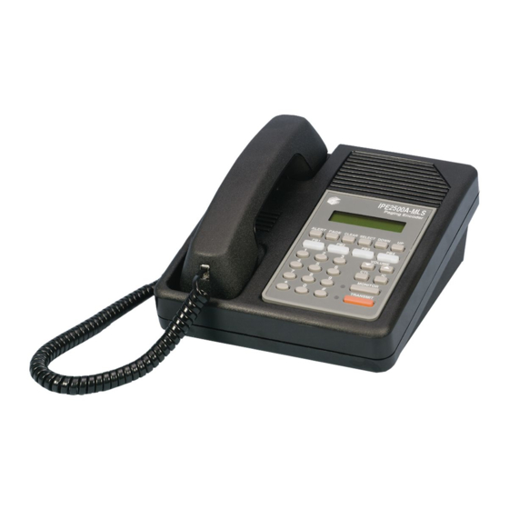
IPE2500A and IPE2500A-MLS
Paging Encoder/Desktop Controller
User and Installation Manual
GAI-Tronics Corporation 400 E. Wyomissing Ave. Mohnton, PA 19540 USA
610-777-1374 800-492-1212 Fax: 610-796-5954
V
.
-
.
ISIT WWW
GAI
TRONICS
COM FOR PRODUCT LITERATURE AND MANUALS
Advertisement
Table of Contents

Related Manuals for GAI-Tronics IPE2500A


Summary of Contents for GAI-Tronics IPE2500A
- Page 1 A H U B B E L L C O M P A N Y IPE2500A and IPE2500A-MLS Paging Encoder/Desktop Controller User and Installation Manual GAI-Tronics Corporation 400 E. Wyomissing Ave. Mohnton, PA 19540 USA 610-777-1374 800-492-1212 Fax: 610-796-5954 ISIT WWW TRONICS...
- Page 2 GAI-Tronics. WARRANTY GAI-Tronics warrants for a period of one (1) year from the date of shipment, that any GAI-Tronics equipment supplied hereunder shall be free of defects in material and workmanship, shall comply with the then-current product specifications and product literature, and if applicable, shall be fit for the purpose specified in the agreed-upon quotation or proposal document.
-
Page 3: Table Of Contents
ARNING CMOS I ..................2 ANDLING OF NTEGRATED IRCUIT EVICES DESCRIPTION................................3 ............................3 EATURES AND ENEFITS IPE2500A P ............4 NTRODUCTION TO THE AGING NCODER ESKTOP ONTROLLER ............................5 UTTON ANEL ........................6 ... - Page 4 Table of Contents IPE2500A and IPE2500A-MLS Paging Encoder/Desktop Controller ..............................18 ECURE PERATION DTMF D ............................... 19 ECODE H.E.A.R. S ..........................19 YSTEM PERATION DC C ............................ 20 PTIONAL ONTROL ..........................20 PTIONAL ELAY ONTROL ...
- Page 5 IPE2500A and IPE2500-MLS Paging Encoder/Desktop Controller Table of Contents DTMF/H.E.A.R. F ........................... 43 UNCTIONS /RS-232 P ........................... 43 UDIO CCESSORY ....................... 44 ICROPHONE ENSITIVITY DJUSTMENTS Internal Microphone ............................44 Handset Microphone ............................44 Accessory Microphone ............................44 .........................
- Page 6 Table of Contents IPE2500A and IPE2500A-MLS Paging Encoder/Desktop Controller 03/12 Pub. 43004-008H...
-
Page 7: Foreword
Foreword Scope of Manual This manual offers descriptive data and service information for the IPE2500A Paging Encoder/Desktop Controller. Service diagrams and printed circuit board details are a part of this service manual. Nomenclature The model number, located on the nameplate on the bottom, specifically identifies GAI-Tronics equipment. -
Page 8: Safe Handling Of Cmos Integrated Circuit Devices
Foreword IPE2500A and IPE2500A-MLS Paging Encoder/Desktop Controller Safe Handling of CMOS Integrated Circuit Devices Many of the integrated circuit devices used in communications equipment are of the Complementary Metal Oxide Semiconductor (CMOS) type. Because of their high open circuit impedance, CMOS integrated circuits are vulnerable to damage from static charges. -
Page 9: Description
Description Features and Benefits Feature Benefit Programmable 16-frequency Any one of 16 EIA standard tones can be programmed for each function control with alias frequency/function key along with an alias for each. LCD display Allows user-friendly interface; displays frequency alias, mode status and diagnostic information. -
Page 10: Introduction To The Ipe2500A Paging Encoder/Desktop Controller
This standard unit is a “tone” control remote. However, by adding the optional field installation kits to the IPE2500A and using the CARD Suite Programming Software, it can be configured for DC, Local, and E&M and tone, allowing further possibilities for remote dispatch. -
Page 11: Desk Set Button Panel
IPE2500A and IPE2500A-MLS Paging Encoder/Desktop Controller Description Desk Set Button Panel Transmit Button and LED : The red button is TRANSMIT used to place the desk set in the transmit mode and to initiate voice transmissions. The LED, located TRANSMIT... -
Page 12: Internal Microphone And Speaker
Rear View of IPE2500A Connectors Power Connector The IPE2500A is powered by a listed ac wall transformer supplying nominal 12 V dc. The operating range is 10.5 to 15 V dc. The five-pin power connector diagram and pinout are shown below: Function −IN... -
Page 13: Line Connector
No connection Audio Accessory/RS-232 Port IPE2500A contains an eight-pin modular desk mic port to provide audio accessory options. Possible accessories include desk mic, gooseneck mic, boom mic, headset, or footswitch. The port is also used as the connector to a PC for CARD Suite programming. -
Page 14: Control Tones
6. This operation is identified as “channel steering.” DTMF Decode/H.E.A.R. System Support The IPE2500A will decode incoming DTMF and display the ID numerically or as a preprogrammed alias. The DTMF decode function will provide H.E.A.R. system support using a base ID DTMF code to perform speaker un-muting and alert functions. -
Page 15: Accessories
IPE2500A and IPE2500A-MLS Paging Encoder/Desktop Controller Description Accessories Description Part No. Desk Microphone (direct connection) XDM004A Desktop Gooseneck Microphone (requires XAAB002A) XDM005A Footswitch (requires XAAB002A) XFS002A Tone Remote Adapter ITA2000A Audio Accessory Box XAAB002A Amplified Headset, Single Earpiece (requires coiled cord) -
Page 16: Performance Specifications
Description IPE2500A and IPE2500A-MLS Paging Encoder/Desktop Controller Performance Specifications Color ..............................Black Physical size ....................7.6 W 8.9 L 4.7 H inches Weight ..............................2.4 lbs. Temperature range ......................−35 C to +70 C Humidity ..................... 95% at 50 C (non-condensing) Line impedance ....................... -
Page 17: Operation
Operation The IPE2500A provides radio system control from a remote location. It sends tone control to the remote adapter through a telephone line to control radio functions such as transmit, channel steering, and monitor. Receive audio from the radio system is sent to the desk sets via the same line connection in two-wire applications, or by using another pair in four-wire applications. -
Page 18: Receiving Calls
Receiving Calls When power is applied, the IPE2500A is in the receive mode, allowing receive audio to be heard through the speaker or handset. It is always in receive mode unless the unit is transmitting, or a parallel desk set is transmitting (parallel mute function enabled). -
Page 19: Handset Transmit
Without the desk mic connected, the connection remains open and the desk set continually sees the key pressed. 2. The IPE2500A has three microphone sensitivity adjustments. Refer to the “Installation” section of this manual. -
Page 20: Front Panel Buttons
CLEAR clearing a capcode entry in paging mode. SELECT button is used to enter the frequency selection mode (not possible on the IPE2500A-MLS), SELECT select a frequency in frequency selection mode or select a paging type in page mode. UP/DOWN BUTTONS... -
Page 21: Ctl (Control) Button
If Direct DTMF dialing is enabled, this method and the use of programmable buttons are the only ways to change the selected frequency. : The button cannot be used for this function on the IPE2500A-MLS. SELECT Keypad Buttons The numeric keypad is used for the selection of a desired frequency page capcode entry and direct DTMF dialing. -
Page 22: Parallel Status Operation
FREQ: XX the selected frequency. Each time the IPE2500A is powered up, the status of the base/radio is unknown. The desk set LCD display flashes the last selected frequency when the unit was powered down. The display continues flashing until a transmission or frequency change is entered, or a parallel unit initiates a transmission or frequency change. -
Page 23: Numeric Keypad Frequency Selection
Operation Numeric Keypad Frequency Selection The IPE2500A can be configured for multiple frequency control with the CARD Suite Programming Software. When the desired frequency is selected using the numeric keypad, that frequency change command is sent to the base. Other parallel units will reflect the newly selected frequency. Note that if Direct DTMF is enabled, the numeric keypad is used for direct DTMF dialing. -
Page 24: Tone Supervisor Control
IPE2500A and IPE2500A-MLS Paging Encoder/Desktop Controller Tone Supervisor Control The IPE2500A offers a tone supervisor control feature which locks out transmission of parallel units upon detection of the proper tone control sequence. This feature cannot be activated during a parallel transmission. -
Page 25: Dtmf Decode
When the field unit presses the PTT button of the radio, the radio generates a preprogrammed sequence of DTMF digits prior to opening the voice path of the radio. The IPE2500A decodes these digits and displays the ID either numerically or with a preprogrammed alias. The dispatcher then knows, without the field radio user having to speak his identity, which radio is being received. -
Page 26: Optional Dc Control Kit
The IPE2500A uses the M lead to signal when to transmit, and the E lead to detect when to receive. Note that the E lead is not required. The M lead must be set on relay module using the CARD Suite software. -
Page 27: E&M With Tone Control
Two-wire or four-wire compatible : The addition of the line select option to the IPE2500A allows the unit to control multiple base stations with one unit using tone remote control. The option is not compatible with dc or local control configurations. -
Page 28: Line Selection
Operation IPE2500A and IPE2500A-MLS Paging Encoder/Desktop Controller Line Selection When the unit is initially powered up, line 1 will be selected and the display will indicate the current lines selected. You can select a line by either of two methods with the proper programming of the unit: Quick-Select, or by using the Line Selection Menu. -
Page 29: Vox-Detect Indication
A pulsed 1500 Hz alert tone; 250 ms on/off. A warble alert tone; 250 ms at 800 Hz, 250 ms at 1500 Hz. button on the IPE2500A allows you to select from two types of alert tones to be transmitted: ALERT ... -
Page 30: Paging
The alias feature allows user-determined names to be assigned to specific paging capcodes. This permits selecting a frequently-used paging sequence by name rather than by re-entering digits on the keypad. Entering the Paging Menu Make sure the IPE2500A is in normal operation. Press the button. The normal status line appears PAGE at the top of the LCD display. -
Page 31: Entering A Programmed Alias
IPE2500A and IPE2500A-MLS Paging Encoder/Desktop Controller Operation Entering a Programmed Alias If paging aliases have been programmed into the desk set, press either the or the button after DOWN entering the paging menu. To scroll alphabetically, press the combination of either buttons. -
Page 32: 2-Tone Paging Example
Operation IPE2500A and IPE2500A-MLS Paging Encoder/Desktop Controller 2-Tone Paging Example Example 1 Suppose the number of 2-Tone keypad digits accepted from the user on the selected channel is 2, and Code Plan R has been selected. The 8-second group call has been selected and the preset 2-Tone digit is 7. - Page 33 IPE2500A and IPE2500A-MLS Paging Encoder/Desktop Controller Operation Example 2 Suppose the number of 2-Tone keypad digits accepted from the user on the selected channel is 2 and the GE code plan has been selected. The preset 2-Tone digit is 4.
- Page 34 Operation IPE2500A and IPE2500A-MLS Paging Encoder/Desktop Controller Tone Group Frequency Chart The chart below cross-references the 2-Tone Paging Code to the frequency in Hz. Tone Group Group # 330.5 349.0 368.5 389.0 410.8 433.7 457.9 483.5 510.5 539.0 569.1 600.9 634.5...
-
Page 35: Plectron Paging
IPE2500A and IPE2500A-MLS Paging Encoder/Desktop Controller Operation Plectron Paging The Plectron paging feature requires a four-digit prefix (capcode). Like 2-Tone paging, the capcode and code plan will determine at what frequency the paging tones will be transmitted. Plectron paging uses the Plectron Code Plan Chart and Plectron Tone Group/Frequency Chart. Refer to the example below and the tables to determine the capcodes you need. - Page 36 Operation IPE2500A and IPE2500A-MLS Paging Encoder/Desktop Controller Plectron Paging Code Plan Chart Most Significant Digits-to-Tone Source 2 (MS) Digits digit tone source digit tone source 2 (MS) Digits digit tone source digit tone source Plectron Tone Group/Frequency Chart (in Hz)
- Page 37 IPE2500A and IPE2500A-MLS Paging Encoder/Desktop Controller Operation 5-Tone Preamble Tone Number Allows the selection of a 5-Tone preamble number from the following list: : This parameter affects alias paging as well. Number Frequency Number Frequency 600 Hz 570 Hz 741 Hz...
-
Page 38: Direct Dtmf Dialing
IPE2500A and IPE2500A-MLS Paging Encoder/Desktop Controller Direct DTMF Dialing The IPE2500A supports a configurable Direct DTMF dialing mode that allows the operator to quickly generate DTMF transmissions without the need to use preprogrammed aliases or the paging operation of the unit. This is useful for controlling repeater operation or accessing remote devices that use DTMF as a selective signaling protocol. -
Page 39: Direct Dtmf Dialing Using Immediate Dtmf Paging
IPE2500A and IPE2500A-MLS Paging Encoder/Desktop Controller Operation Direct DTMF Dialing Using Immediate DTMF Paging If DTMF paging is enabled, it is possible to use the immediate DTMF paging feature to generate DTMF digits as well. The operation of direct DTMF dialing in the mode of operation is the same as timed direct DTMF dialing with the hang time being 2 seconds instead of the configured direct DTMF hang time. -
Page 40: Rs-232 Input Or Pc Control
Operation IPE2500A and IPE2500A-MLS Paging Encoder/Desktop Controller RS-232 Input or PC Control The RS-232 input feature allows a computer to send information, which will cause the desk set to initiate a page (without talk time), frequency change or custom tone transmission. -
Page 41: Frequency Changing
‘~’ (Acknowledge that frequency change is complete) Custom Tones Custom tones allow the PC to direct the IPE2500A to initiate a transmission and generate a specified tone frequency. The unit remains keyed to allow additional tones to be generated until the PC directs the IPE2500A to cease transmission. - Page 42 Operation IPE2500A and IPE2500A-MLS Paging Encoder/Desktop Controller Example: The frequency constant is calculated as (using C syntax): MSW = 0x00ff & round (frequency * 8.192 ) >> 1 LSW = 0xFF00 & round (frequency * 8.192 ) >> 8 Therefore, to generate 1234 Hz followed by 567 Hz the frequency constants must first be calculated.
-
Page 43: Installation
Installation Planning the Installation IPE2500A Sample Installation Diagram - Shown connected in parallel. Mechanical Receipt Inspection The desk sets are shipped in a cardboard container with inserts. Thoroughly inspect it as soon as possible after delivery. In-transit damage should be immediately reported to the transportation company. -
Page 44: Electrostatic Discharge (Esd) Protection
IPE2500A and IPE2500A-MLS Paging Encoder/Desktop Controller Electrostatic Discharge (ESD) Protection The IPE2500A have ESD protection circuitry that provides a high degree of protection against ESD, and power and telephone line surges. The circuitry shunts the transient currents to earth ground through the ground terminal. -
Page 45: Line Connection
IPE2500A and IPE2500A-MLS Paging Encoder/Desktop Controller Installation Line Connection Connect the telephone line to the modular connector located on the back of the desk set. Refer to the pinout on page 6 of the “Connectors” section of this manual. Observe right to left pinout for pins 1 through 6. -
Page 46: Multi - Line Select (Ipe2500A-Mls)
: This operation requires IPE2500A-MLS Desk Set or XMLS001A Field Install Kit. The IPE2500A MLS should have a default archive programmed into it. If it does not, or if the XMLS001A was purchased, install and configure the Line Select Option as follows: Programming Changes The following are necessary programming changes to make after installation of the line select option. -
Page 47: Mls Line-Level Normalization
If not properly adjusted, the audio from one line may keep the IPE2500A compressor in compression. When the audio causing the compression is removed, and the compressor releases, it causes the lower audio levels to increase in perceived volume. -
Page 48: Line Connection For Mls
Installation IPE2500A and IPE2500A-MLS Paging Encoder/Desktop Controller Line Connection for MLS After completing the steps above, connect the lines. Use the table below to determine the line connections on the Line Select board. Description Line 1 Two-wire RX/TX/four-wire TX tip... -
Page 49: Dtmf/H.e.a.r. Functions
Installation DTMF/H.E.A.R. Functions As noted in the “Operation” section of this manual, the IPE2500A must be manually placed in “mute” mode when used in a H.E.A.R. operation. This requires that one of the function keys to be programmed for mute operation. While in CARD Suite under the IPE2500A programming archive, select the Programmable Buttons tab. -
Page 50: Microphone Sensitivity Adjustments
IPE2500A and IPE2500A-MLS Paging Encoder/Desktop Controller Microphone Sensitivity Adjustments After connections have been made, the IPE2500A must be configured for transmit and receive audio levels. These adjustments are made using the front panel buttons. The microphone sensitivity adjustment is used to compensate for different user voice levels and varied acoustical conditions. Refer to the following instructions to adjust the different microphones. -
Page 51: Level Adjustments And Diagnostics
IPE2500A and IPE2500A-MLS Paging Encoder/Desktop Controller Installation Level Adjustments and Diagnostics Main Diagnostics Selection To enter the main programming mode: 1. Remove power from the desk set. 2. Reapply power and wait for the through to illuminate. (The display will indicate PB4 LED “checking parameters - please wait.”) Press... - Page 52 Installation IPE2500A and IPE2500A-MLS Paging Encoder/Desktop Controller The diagram below illustrates which buttons to press to access the programming menu features. Press: To program: Line Output Adjust Default: −10 dB Line Input Sensitivity Default: −9 dB Internal Diagnostics: Press: To program:...
-
Page 53: Reloading Factory Defaults
IPE2500A and IPE2500A-MLS Paging Encoder/Desktop Controller Installation Reloading Factory Defaults Desk sets are shipped from the factory with default settings that meet most installation requirements. However, it is important to verify that these parameters are adjusted to meet your specific installation needs. - Page 54 Line Out Adjust for the IPE2500-MLS The IPE2500A-MLS allows the adjustment of each of the four available lines. When setting line output levels for an MLS desk set, follow the same procedure described above but select the appropriate line to adjust using the programmable buttons: PB1 for line 1, PB2 for line 2, PB3 for line 3 and PB4 for line 4.
-
Page 55: Pb2 - Line-In Sensitivity
IPE2500A and IPE2500A-MLS Paging Encoder/Desktop Controller Installation PB2 - Line-In Sensitivity After entering the main programming selection mode, press the button to allow adjustment of the line-in sensitivity. This adjustment allows the desk set to compensate for a range of 0 to 15 dB of line loss in 3-dB increments. -
Page 56: Pb3 - Internal Diagnostics
TRANSMIT MLS Module: If the MLS module is installed (included in the IPE2500A-MLS or XML001A Kit) the Line Select board diagnostic replaces the relay module diagnostics shown above. This diagnostic allows the line select module to be exercised. - Page 57 IPE2500A and IPE2500A-MLS Paging Encoder/Desktop Controller Installation PB2 – DC Module Diagnostics This function is selected after entering Internal Diagnostics ( DC Module: If the dc module (XDC0001A Kit) is installed, this mode allows the board to be exercised with both positive and negative currents and sets the DCLOTL. The threshold for DCLOTL is adjustable, but is factory preset for most installations.
- Page 58 Installation IPE2500A and IPE2500A-MLS Paging Encoder/Desktop Controller PB3 – RS-232 Diagnostic This function is accessible via Main Diagnostics, then Internal Diagnostics ( ), and exercises the RS- 232 port TX and RX data. To run this test, disconnect anything connected to the programming connector on the back of the unit, and short pins 2 and 7 of the connector.
-
Page 59: Pb4 - Tone Level Adjust
IPE2500A and IPE2500A-MLS Paging Encoder/Desktop Controller Installation PB4 – Tone Level Adjust This function is accessible via Main Diagnostics mode select ( ), and allows adjustment of the levels of sidetone ( ), the alert tones ( ), and the page tones ( ). -
Page 60: Ctl-Pb1- Toggle Compressors
Installation IPE2500A and IPE2500A-MLS Paging Encoder/Desktop Controller CTL-PB1– Toggle Compressors This function is accessible via Main Diagnostics mode select (CTL- ), and allows the microphone ) and audio receive compressor ( ) to be enabled or disabled. The factory default is that both compressors are enabled. -
Page 61: Theory Of Operation
Theory of Operation General Desk Set Overview The IPE2500A is a multi-processor design employing state-of-the-art DSP technology to achieve superior performance over typical analog and single-processor designs. This allows for ultimate flexibility in audio processing. The heart of the design consists of U1, the DSP; and U3, the microcontroller. The DSP is responsible for audio processing of receive and transmit audio. -
Page 62: Transmit Audio
This compressor can be disabled using the desk set diagnostics. Guard Tone Detection When configured for tone control operation, the IPE2500A must detect guard-tone from parallel units to restrict transmissions. This is done by first auto-leveling the transmit audio input from line 1 using U12. -
Page 63: Dc Control Module (Not Compatible With Mls Operation)
IPE2500A and IPE2500A-MLS Paging Encoder/Desktop Controller Theory of Operation DC Control Module (not compatible with MLS operation) The reference designators listed in this section refer to the dc control schematics unless otherwise stated. The dc control module provides a method of generating dc control currents on line 1 and detecting line voltages to restrict transmission during a parallel transmit. -
Page 64: Multi-Line Select Module
Theory of Operation IPE2500A and IPE2500A-MLS Paging Encoder/Desktop Controller Multi-Line Select Module The reference designators listed in this section refer to the multi-line select schematics unless otherwise stated. The transmit and receive audio paths to and from the desk set are routed to the NSL PCBA through P802. -
Page 65: Card Suite Programming Software
Connection The GAI-Tronics equipment must be connected to your personal computer with the programming cable, part number XAC0004A, before the programming software can be used. To make this connection, attach the cable to the COM1 or COM2 connector on the computer. -
Page 66: Card Suite Programming
CARD Suite Programming IPE2500A & IPE2500A-MLS Paging Encoder/Desktop Controller CARD Suite Programming To program a unit that has no saved archive, follow the steps for Reading the Unit on the previous page. To open an existing archive for editing, first click on the appropriate product icon, then double click on the archive you wish to edit from the list of saved archives. -
Page 67: Troubleshooting
Troubleshooting Troubleshooting the IPE2500A Desk Set The following is a list of potential problems you may encounter and possible solutions. Problem Possible Solution The unit has no LED or Ensure that the unit is receiving dc power. LCD display Check for a blown fuse. -
Page 68: Fuse Replacement
SELECT selected frequency. to enter the frequency selection mode. If direct DTMF is enabled and this is an IPE2500A-MLS, frequency selection is not possible except through the use of programmable buttons. Fuse Replacement CAUTION For continued safe operation, replace fuses with the same type. -
Page 69: Circuit Boards
Circuit Boards 03/12... - Page 70 Circuit Boards IPE2500A and IPE2500A-MLS Paging Encoder/Desktop Controller...
- Page 71 IPE2500A and IPE2500A-MLS Paging Encoder/Desktop Controller Circuit Boards...
- Page 72 Circuit Boards IPE2500A and IPE2500A-MLS Paging Encoder/Desktop Controller Multi-Line Select Board (IPE2500A-MLS)
-
Page 73: Schematics
Schematics 03/12... - Page 74 Schematics IPE2500A and IPE2500A-MLS Paging Encoder/Desktop Controller Tone RC Desk Set - Line Interface - Sheet 1...
- Page 75 IPE2500A and IPE2500A-MLS Paging Encoder/Desktop Controller Schematics Tone RC Desk Set - User Audio I/O - Sheet 2...
- Page 76 Schematics IPE2500A and IPE2500A-MLS Paging Encoder/Desktop Controller Tone RC Desk Set - Control Microprocessor I/O - Sheet 3...
- Page 77 IPE2500A and IPE2500A-MLS Paging Encoder/Desktop Controller Schematics Tone RC Desk Set - DSP Block - Sheet 4...
- Page 78 Schematics IPE2500A and IPE2500A-MLS Paging Encoder/Desktop Controller Tone RC Desk Set - Tone Key Panel - Sheet 5...
- Page 79 IPE2500A and IPE2500A-MLS Paging Encoder/Desktop Controller Schematics Tone RC Desk Set Power Supply - Sheet 6...
- Page 80 Schematics IPE2500A and IPE2500A-MLS Paging Encoder/Desktop Controller Schematic - Sheet 7...
- Page 81 IPE2500A and IPE2500A-MLS Paging Encoder/Desktop Controller Schematics Schematic – Sheet 8 DPS PCBA...
- Page 82 Schematics IPE2500A and IPE2500A-MLS Paging Encoder/Desktop Controller Multi-Line Select Sheet 1 of 4 (5/02)
- Page 83 IPE2500A and IPE2500A-MLS Paging Encoder/Desktop Controller Schematics Multi-Line Select Sheet 2 of 4...
- Page 84 Schematics IPE2500A and IPE2500A-MLS Paging Encoder/Desktop Controller Multi-Line Select - Sheet 3 of 4...
- Page 85 IPE2500A and IPE2500A-MLS Paging Encoder/Desktop Controller Schematics Multi-Line Select Sheet 4 of 4...
- Page 86 Schematics IPE2500A and IPE2500A-MLS Paging Encoder/Desktop Controller...
-
Page 87: Definitions And Acronyms
Definitions and Acronyms Term Definition Carrier squelch A means of grouping users of a common radio channel. Subaudible tones are transmitted CTCSS with audio; a particular radio’s speaker (or the speakers of a group of radios) will unmute to broadcast a transmission only if the associated subaudible tone identifies it as belonging to the radio’s user group.
Need help?
Do you have a question about the IPE2500A and is the answer not in the manual?
Questions and answers