Table of Contents
Advertisement
Quick Links
Model 227-005, 247-005, 257-005,
and 277-005 SMART Auto-Dial
Confidentiality Notice .....................................................................................................................1
Product Overview ............................................................................................................................1
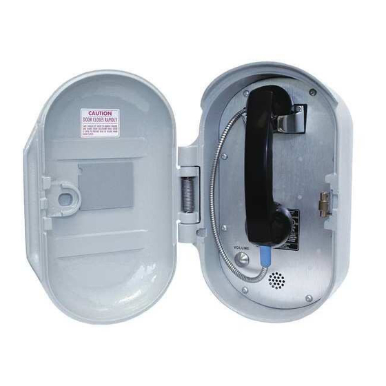
Telephones ............................................................................................................................................... 1
Telephone Management Application (TMA) ....................................................................................... 2
Existing TMA Application (pre-version 7.4.1 software) ...................................................................................... 3
TMA Upgrade (free) ............................................................................................................................................. 3
Standard Operation .........................................................................................................................4
Volume Control Button .......................................................................................................................... 4
Receiving a Call ....................................................................................................................................... 4
Placing a Call ........................................................................................................................................... 4
Disconnecting a Call ............................................................................................................................... 4
Installation ......................................................................................................................................5
Safety Guidelines ..................................................................................................................................... 5
General Installation Guidelines ............................................................................................................. 6
High Noise Area Installation .................................................................................................................. 7
Security Hardware .................................................................................................................................. 8
Conduit Installation Details (Applicable to Models 247-005 and 257-005) ........................................ 8
Model 227-005 ....................................................................................................................................... 10
Model 247-005 ....................................................................................................................................... 12
Model 257-005 ....................................................................................................................................... 14
Model 277-005 ....................................................................................................................................... 16
Stanchion or Flush-mount Applications.............................................................................................................. 16
Surface-Mount Applications ............................................................................................................................... 17
External Power for Lower Operating Temperatures ........................................................................ 18
Setup ..............................................................................................................................................19
Hardware Configuration ...................................................................................................................... 19
Auto-answer Configuration ................................................................................................................................ 19
Polarity Configuration ........................................................................................................................................ 19
GAI-TRONICS 3030 KUTZTOWN RD. READING, PA 19605 USA
V
ISIT WWW
G A I - T R O N I C S ®
A H U B B E L L C O M P A N Y
Handset Telephones
T
A B L E O F
610-777-1374 800-492-1212 Fax: 610-796-5954
.
-
.
GAI
TRONICS
COM FOR PRODUCT LITERATURE AND MANUALS
C
O N T E N T S
Pub. 42004-443C
Advertisement
Table of Contents

Related Manuals for GAI-Tronics 227-005


Summary of Contents for GAI-Tronics 227-005
-
Page 1: Table Of Contents
Setup ..............................19 Hardware Configuration ........................19 Auto-answer Configuration ..........................19 Polarity Configuration ............................19 GAI-TRONICS 3030 KUTZTOWN RD. READING, PA 19605 USA 610-777-1374 800-492-1212 Fax: 610-796-5954 ISIT WWW TRONICS COM FOR PRODUCT LITERATURE AND MANUALS... - Page 2 Preventive Maintenance for Model 277-005 ..................27 Cleaning ................................27 Prevention ................................27 Specifications ..........................28 GAI-TRONICS 3030 KUTZTOWN RD. READING, PA 19605 USA 610-777-1374 800-492-1212 Fax: 610-796-5954 ISIT WWW TRONICS COM FOR PRODUCT LITERATURE AND MANUALS...
-
Page 3: Confidentiality Notice
GAI-Tronics product or system. This manual may not be disclosed in any form, in whole or in part, directly or indirectly, to any third party. -
Page 4: Telephone Management Application (Tma)
Each telephone requires a minimum line current of 20 mA for proper operation. For operation below −4º F (−20° C), GAI-Tronics offers a plug-in power supply (120 V ac required), which will allow operation to −40° C. Please refer to page 18. -
Page 5: Existing Tma Application (Pre-Version 7.4.1 Software)
TMA Upgrade (free) GAI-Tronics offers a free upgrade to customers currently utilizing a TMA system that is operating from a pre 7.4.1 version. To take advantage of this free upgrade, please visit our website at www.gai- tronics.com:... -
Page 6: Standard Operation
Pub. 42004-443C 4 of 31 SMART A ANDSET ELEPHONES Standard Operation Volume Control Button The volume control button on the front panel of each telephone is used to control the handset receiver volume. The handset volume is pre-set/pre-programmed into each telephone to provide an initial handset volume when the handset is removed from its cradle. -
Page 7: Installation
Installation should be performed by qualified personnel and only in accordance with the National Electrical Code or applicable local codes. Safety Guidelines When installing any GAI-Tronics telephone equipment, please adhere to the following guidelines to ensure the safety of all personnel: ... -
Page 8: General Installation Guidelines
Additional “line sharing” or “party line” configuration issues could include sporadic telephone operation, difficulties with programming, or premature disconnection of calls. A GAI-Tronics Model 12600-xxx Line Current Booster assembly may be a viable solution for improving the effects of low line current. -
Page 9: High Noise Area Installation
Pub. 42004-443C 7 of 31 SMART A ANDSET ELEPHONES High Noise Area Installation Installing a SMART Telephone in a high noise area may require the use of an external audible or visual device for ringing notification. Utilizing one of these devices differs from an installation utilizing a standard analog telephone. -
Page 10: Security Hardware
ELEPHONES Security Hardware Models 227-005 and 277-005 are vandal-resistant, with the front panel for each telephone attached to its enclosure with security screws. A GAI-Tronics Model 233-001 Security Screwdriver or Torx T-25 security head tip (sold separately) is recommended for installing the security screws. Model 247-005 and 257-005 Telephones’... - Page 11 Pub. 42004-443C 9 of 31 SMART A ANDSET ELEPHONES Figure 1. Bottom entry conduit installation details (RECOMMENDED for non-metallic enclosures) Figure 2. Top entry conduit installation details (NOT RECOMMENDED) f:\standard ioms - current release\42004 instr. manuals\42004-443c.doc 02/13...
-
Page 12: Model 227-005
SMART A ANDSET ELEPHONES Model 227-005 The mounting and wiring instructions for the Model 227-005 SMART Telephone are as follows: 1. Remove the eight security screws from the front panel. Remove the front panel and set aside. : There is a 7-foot half- modular telephone cord attached to the PCBA on the rear. - Page 13 Sensitivity potentiometer locations. 9. Verify operation by calling to and from another telephone. Figure 5. Model 227-005 Mounting Details 10. Replace the front panel assembly, and secure using the eight front panel security screws. f:\standard ioms - current release\42004 instr. manuals\42004-443c.doc...
-
Page 14: Model 247-005
Pub. 42004-443C 12 of 31 SMART A ANDSET ELEPHONES Model 247-005 1. Remove the four screws from the front panel. Remove the front panel and set aside. : There is a 7-foot half-modular telephone cord attached to the PCBA on the rear. Figure 6. - Page 15 Pub. 42004-443C 13 of 31 SMART A ANDSET ELEPHONES 7. Using the “Setup” section of this manual, Configure the hardware as required. Refer to the “Hardware Configuration” section on page 19 for details. Adjust the audio levels, if necessary. Refer to Figure 13 for Receiver Volume and Microphone Sensitivity potentiometer locations.
-
Page 16: Model 257-005
Pub. 42004-443C 14 of 31 SMART A ANDSET ELEPHONES Model 257-005 1. Open the front door and remove the four outer screws from the mid-section. Carefully pull the enclosure apart until encountering a slight resistance on the left side. Figure 8. Model 257-005 SMART Auto-Dial Telephone Outline (Front door open) 2. - Page 17 Pub. 42004-443C 15 of 31 SMART A ANDSET ELEPHONES 8. Using the “Setup” section of this manual, Configure the hardware as required. Refer to the “Hardware Configuration” section on page 19 for details. Adjust the audio levels, if necessary. Refer to Figure 13 for Receiver Volume and Microphone Sensitivity potentiometer locations.
-
Page 18: Model 277-005
Figure 10. Model 277-005 Outline Drawing Stanchion or Flush-mount Applications 1. When mounting in a GAI-Tronics Model 234 Series Stanchion or for flush-mount installations, the supplied back box must be used to mount the Model 277-005 Telephone. Mount the back box to the structure using the appropriate hardware. -
Page 19: Surface-Mount Applications
Pub. 42004-443C 17 of 31 SMART A ANDSET ELEPHONES 7. Using the “Setup” section of this manual, Configure the hardware as required. Refer to the “Hardware Configuration” section on page 19 for details. Adjust the audio levels, if necessary. Refer to Figure 13 for Receiver Volume and Microphone Sensitivity potentiometer locations. -
Page 20: External Power For Lower Operating Temperatures
Pub. 42004-443C 18 of 31 SMART A ANDSET ELEPHONES Figure 11. Model 277-005 Mounting Details External Power for Lower Operating Temperatures The Model 40404-045 Plug-In Power Supply is available (sold separately) to ensure stable operation between −20º C and −40º C. The 40404-045 requires 120 V ac input and provides a 5 V dc output to the unit’s amplifier circuits. -
Page 21: Setup
Disable: J14 jumper in position DIS (Use this setting only if “call-in” data collection operation is desired.) : The Auto-answer feature must be enabled to allow the GAI-Tronics’ Telephone Management Application PC to contact the telephone or to allow remote Touch Tone programming. -
Page 22: Command Select Configuration
Pub. 42004-443C 20 of 31 SMART A ANDSET ELEPHONES Command Select Configuration Factory Setting: Auto Jumper J20 is required to be in the factory set position. Do not remove the jumper from the PCBA. AUX2 Input Configuration Factory Setting: AUX2 Jumper J12 selects an option to use the AUX2 input (TB7) for the cradle hookswitch connection. -
Page 23: Handset Receiver Volume Adjustment
Pub. 42004-443C 21 of 31 SMART A ANDSET ELEPHONES Handset Receiver Volume Adjustment push button on the front panel allows the user to select one of five preset volume levels. At VOLUME its factory default setting, the volume level at the start of a call will be the lowest of the five preset levels. Each momentary press of the button bumps the level up one step;... - Page 24 Auxiliary Control Example: Output 4, Used for Gate Entry A Model 227-005 SMART Telephone is installed at the entrance to a gated/secure community. A visitor or delivery person approaches the gate and places a call to the security office. Upon verification of approved entry, the security guard presses the pre-programmed, DTMF “open gate”...
- Page 25 Pub. 42004-443C 23 of 31 SMART A ANDSET ELEPHONES Figure 13. SMART Telephone PCBA f:\standard ioms - current release\42004 instr. manuals\42004-443c.doc 02/13...
-
Page 26: Programming
More advanced programming requires a PC and the TMA software. For programming using TMA, refer to the user guide included with the software, or contact the GAI-Tronics Field Service Department. NOTE Use a handset telephone exclusively when programming the SMART Telephone remotely. -
Page 27: Basic Programming
Pub. 42004-443C 25 of 31 SMART A ANDSET ELEPHONES Basic Programming The following programming command can be entered from any touch-tone telephone. Acceptance of a data transfer command is indicated via a return code transmitted as an audible DTMF tone. Auto-dial Memory When the handset is lifted from the cradle, the SMART Telephone dials a pre-programmed telephone number (the primary number). - Page 28 Pub. 42004-443C 26 of 31 SMART A ANDSET ELEPHONES Call Time-out The call time-out feature, which is used to limit the duration of calls, can be set between 1 minute and 4.5 hours. The time limit is set by entering a number from 120 to 32400. This number represents the number of 0.5-second increments of duration.
-
Page 29: Maintenance
If your SMART Telephone requires service, contact your GAI-Tronics Regional Service Center for technical support or to obtain a return authorization number (RA#). Equipment returned to GAI-Tronics should be shipped prepaid with a return authorization number marked on the carton. If the equipment is under warranty, repairs will be made without charge. -
Page 30: Specifications
Mechanical Operating temperature range (refer to page 18) ........−4º F to +140º F (−20º C to +60º C) Relative humidity ....................to 95%, no condensation Model 227-005 Construction Enclosure ............Thick-walled cast aluminum with protective gray coating Panel ......................0.125-inch brushed aluminum Handset/cord ............ - Page 31 Pub. 42004-443C 29 of 31 SMART A ANDSET ELEPHONES Model 277-005 Construction Front panel ............14-gauge (0.075 inch) type 304 brushed stainless steel Back box .......... 16-gauge (0.060) cold-rolled steel with black polyurethane finish Handset/cord ............G-style with 29-inch armored cord and internal lanyard Dimensions Front panel ................
- Page 32 REN is separately shown on the label. If this equipment [GAI-Tronics telephone] causes harm to the telephone network, the telephone company will notify you in advance that temporary discontinuance of service may be required. But if advance notice isn’t practical, the telephone company will notify the customer as soon as possible.
- Page 33 Pub. 42004-443C 31 of 31 SMART A ANDSET ELEPHONES Replacement Parts 227- 247- 257- 277- Part No. Description 233-001 Model 233-001 Security Screwdriver 12562-110 PCBA Replacement Kit (SMART Handset) 13707-008 Ringer ...
- Page 34 Warranty Equipment. GAI-Tronics warrants for a period of one (1) year from the date of shipment, that any GAI-Tronics equipment supplied hereunder shall be free of defects in material and workmanship, shall comply with the then-current product specifications and product literature, and if applicable, shall be fit for the purpose specified in the agreed-upon quotation or proposal document.
Need help?
Do you have a question about the 227-005 and is the answer not in the manual?
Questions and answers