Table of Contents
Advertisement
Quick Links
Advertisement
Table of Contents

Related Manuals for REMKO VRS 25 E


Summary of Contents for REMKO VRS 25 E
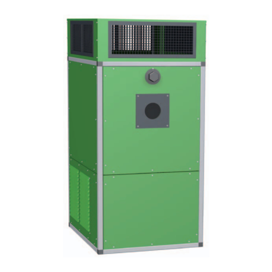
- Page 1 REMKO VRS Universal Heaters Operation · Technology · Spare Parts Edition GB – N01...
-
Page 3: Table Of Contents
Contents Safety information Unit description Safety devices Installation instructions Chimney duct Installation and assembly Commissioning Switching off Care and maintenance Troubleshooting Maintenance log Intended use Customer service and warranty Environmental protection and recycling Wiring diagram 230V Wiring diagram 400V direct starting Wiring diagram 400V Y/Δ... -
Page 4: Safety Information
REMKO VRS Safety information Operation of the heaters must always take place in compliance with the local building and fire protection regulations and regulations of the employers‘ liability insurance associations. A protection zone of 1 m dis- dis- The heaters were subjected to ■... - Page 5 Further plus points include quick Mode of operation and easy installation and ease of servicing. After switching on the heaters by In the event of irregularities or setting the switch to the „Heat“ or extinguishing of the flame, the The heaters comply with the basic „I“...
- Page 6 DIN EN 14597. controller has a sensor monitor and is cold resistant to -20°C. REMKO triple function combination controller The heater switches off at a tem- perature below -20°C and switches on again when the temperature rises.
-
Page 7: Safety Devices
DIN EN 14597. and is cold resistant to -20°C. The heater switches off at a tem- REMKO fourfold function combination controller perature below -20°C and switches on again when the temperature rises. -
Page 8: Installation Instructions
REMKO VRS Installation instructions Installation of the heaters must Selection of site of Combustion air supply generally take place in compliance installation with the directives of the buil- A sufficient supply of combustion ding regulations (LBO) and the The following must be observed... - Page 9 if the appliances are installed in Installation rooms that have an opening or pipe leading to the outside. The heaters must only be The heaters must be installed ■ ■ The cross-section of the opening installed and operated in rooms and mounted so that they are must be minimum 150 cm if they are supplied with suf-...
- Page 10 REMKO VRS Floor mounting Where auxiliary equipment is mechanical damage. ■ required for monitoring, main- The heaters must be installed on tenance and repair, this must be ATTENTION stable, flame retardant surfaces provided by the operator. The measured pressure in the and outside traffic zones, e.g.
-
Page 11: Chimney Duct
Chimney duct Annual inspection The heaters must be connected to Chimney systems must be di- ■ and maintenance a suitable and approved chimney mensioned according to internal system. cross-section and height so that Depending on the particular the exhaust fumes are dischar- NOTE operating conditions, the heating ged to the outside in all normal... - Page 12 Indoor installation The chimney system components 8 / 9 are easily connected by insertion and securing with clamps. All REMKO stainless steel chimney systems are generally approved for building installation by the Institute for Structural Engineering. Example of horizontal installation...
-
Page 13: Installation And Assembly
Installation and assembly For installation of the heating Room thermostat connection NOTE appliances, the requirements Air intake must only take place and regulations applicable in the The room thermostat (accessory) via the air intake openings respective federal state must be must be mounted at a position provided. - Page 14 REMKO VRS 400V type heaters Gas connection The connection of a room thermo- he connection of a room thermo- The burner must be set to the A sufficient gas volume and gas ■ stat or a day/night temperature full heat load of the appliance.
-
Page 15: Commissioning
Commissioning Y / Δ - starting Commissioning of fan motor Commissioning ■ The measured rated current Testing drive must not exceed the value Commissioning of the unit and the shown on the motor rating forced-air burner must take place 1. The mounting screws of the plate. -
Page 16: Switching Off
REMKO VRS The burner must be set to the Heating Ventilate ■ values specified by the manu- facturer, however at least to the The appliances operate fully auto- 1. Set the switch on the control values specified by the Federal matically depending on the room box to the „II“... -
Page 17: Care And Maintenance
Cleaning and maintenance The operator is obliged to have the The limitation of exhaust fume Soot deposits ■ system inspected at least once a losses must be maintained in year for correct operation, reli- reli- accordance with § 1, paragraph Small soot deposits on the heat ability, efficiency and maintenance 1 of the Ordinance on Small... - Page 18 Damaged or deformed seals A special boiler cleaning set must be replaced. for the REMKO industrial 2. Shut off the fuel supply. vacuum cleaner is available as 13. Burner maintenance must be carried out as specified in the an accessory.
-
Page 19: Troubleshooting
Troubleshooting The heater does not start Possible causes: The burner does not start Check the local mains supply ■ connection. The heaters could not cool Check the oil filter for clogging. ■ ■ down because the power supply Replace clogged filter(s). Check the fuses in the control was interrupted. - Page 20 Check the local mains supply ■ connection. ATTENTION With VRS 25 E and 50 heating ■ Adjustment and maintenance appliances, the burner starts Check the fan and drive for ■ of the appliance and forced-air with a delay due to the oil pre- smooth operation.
-
Page 21: Maintenance Log
✍ Maintenance log Model: ........Model No.: ........10 11 12 13 14 15 16 17 18 19 20 Appliance cleaned – externally – Appliance cleaned – internally – Fan blades cleaned V-belt tension checked V-belt replaced Combustion chamber cleaned Heat exchanger cleaned Flue gas brakes replaced Inspection cover seals replaced... -
Page 22: Intended Use
„Warranty Think of the environment when cial use (not for domestic heating). Document” to REMKO GmbH & disposing of the packaging Co. KG at the time of sale and material. With appropriate fan and motor commissioning. -
Page 23: Wiring Diagram 230V
An emergency switch must be provided at an = Capacitor easily accessible point in the installation room KB = REMKO triple function combination controller (however outside any danger zone) . KL = Terminal strip in control box M = Fan motor... -
Page 24: Wiring Diagram 400V Direct Starting
X1 = Terminal strip 1 in control box K1 = Fan contactor X2 = Terminal strip 2 in control box KB = REMKO triple function combination controller M = Fan motor = Time counter (optional) We reserve the right to make dimensional and design changes in the interest of technical advances. -
Page 25: Wiring Diagram 400V Y/Δ Starting
Wiring diagram 400V Y/Δ starting Fan motor: 400V/3~ (up to 3.0 kW) Burner motor: 230V/1~ Lüften Heizen Optional 9 10 11 12 Brenner 1 Brenner 2 L1 N T1 T2 S3 B4 PE T8 T7 T6 B5 Optional Vierfach-Kombinationsregler Quadruple combination The Wieland plug Wielandstecker Stage 2... -
Page 26: Wiring Diagram 400V Fan Motor
REMKO VRS Wiring diagram 400V fan motor Fan motor: 400V/3~ (from 3.0 kW) Burner motor: (400V/3~ optional) Legende: F1 = Fuse block, fan motor M1 = Fan motor F2 = Fuse block, burner motor (optional) RT = Room thermostat or control (optional) -
Page 27: Exploded Drawing
Exploded drawing VRS 25 E - 200 Fig. VRS 50 standard type Replacement for Pos. 6 from size Fig. Fan with belt drive 130 to 200 33 32 We reserve the right to make dimensional and design changes in the interest of technical advances. -
Page 28: Spare Parts List
REMKO VRS Spare parts list No. Designation VRS 25E VRS 50E VRS 75E VRS 100E VRS 130E VRS 170E VRS 200E EDP No. EDP No. EDP No. EDP No. EDP No. EDP No. EDP No. 1 Unit frame, complete 1103200... -
Page 29: Appliance Specifications
Appliance specifications - vertical HB 90 VRS 50 - vertical We reserve the right to make dimensional and design changes in the interest of technical advances. - Page 30 REMKO VRS Appliance specifications - horizontal HB 90 VRS 50 - horizontal/left Legend: = Metal panel Pos. I-III = Metal panel Pos. IV = Burner box = Dust filter 3-sided for free air intake = Dust filter for duct connection = Air outlet hood 3 or 4-sided = Air inlet including grille Pos.
-
Page 31: Unit Dimensions
Weight kg 1542 1792 Weights without burner and other accessories. The dimensions D/E/K and G refer only to REMKO air inlet and outlet accessories. We reserve the right to make dimensional and design changes in the interest of technical advances. -
Page 32: Accessories
REMKO VRS Accessories For direct air outlet to 2, 3 or 4 sides, with built-in air directing shutter flaps. All flaps are individually horizontally and vertically adjustable.. Air outlet hood type HG Dim. in 850 1000 1250 1250 1525 1650 1650 1600 1600 2155 2155... - Page 33 Accessories U-profile construction for mounting vertical or horizontal units Wall bracket type KN on walls with a minimum thickness of 24 cm (structural calculation required). Recommended is the use of continuous M 16 steel reinforced threaded bolts (local mounting material) Appliance type dim.
- Page 34 REMKO VRS Accessories Duct filter with easy to change insertion filters with the filter class G3. Further filter classes are available on request. Dust filter Type FK for duct inlet Any unused air inlet openings must be closed with appropriate metal plates.
-
Page 35: Technical Data
Technical data Series Symbol Unit 25 E 50 E 75 E 100 E 130 E 170 E 200 E 270 E 340 E 440 E 540 E Q ̇ Nominal heat load Nominal heat output 29,0 50,0 81,0 110,0 149,0 193,0 232,0 254,0 305,0 405,0 499,0 rated,h Minimum power 56,7... - Page 36 REMKO VRS 1) Air flow at Δ 40K / 1.2 kg/m 2) The specified nozzle sizes and pump pressures result from adjustments on the test stand. The oil flow rate was determined by volumetric measurement. Owing to product-specific nozzle and pressure tolerances as well as the oil temperature, the values shown are only guide values.
-
Page 37: Technical Data Of Drive
Technical data of drive Electric motor(s) Fan(s) V-belt wheels Nom. press. Electrical Power con- Rated Rated Sound pres- Type Type Speed Type Motor external connection sumption current speed sure level mm Ø mm Ø dB(A) 230/1~ 0.20 2.20 DD 9/9 Direct drive 230/1~ 0.245... - Page 38 REMKO VRS...
- Page 40 SFlb Customer Service Our equipment operates precisely and reliably. However, in the event of a fault, REMKO customer service is quickly at REMKO GmbH & Co. KG the scene. Our comprehensive Air conditioning and heating technology network of experienced dealers...
Need help?
Do you have a question about the VRS 25 E and is the answer not in the manual?
Questions and answers