
Related Manuals for Beckhoff EP7402-0057


Summary of Contents for Beckhoff EP7402-0057
- Page 1 Documentation | EN EP7402-0057 2-channel motor controller box for roller conveyor systems 2020-11-02 | Version: 1.0...
-
Page 3: Table Of Contents
Restoring the delivery state ...................... 33 Decommissioning .......................... 34 5 Troubleshooting ............................ 35 Common problems .......................... 35 Warnings and errors ........................ 35 Diagnosis bits .......................... 36 6 Application Notes ............................ 38 Motor Diagnosis.......................... 38 7 CoE objects .............................. 39 Register ............................ 39 Object descriptions .......................... 40 7.2.1 Parameterization objects .................... 40 EP7402-0057 Version: 1.0... - Page 4 7.2.2 Information objects ...................... 43 7.2.3 Standard objects...................... 44 8 Appendix .............................. 45 Example motor parameters ...................... 45 General operating conditions...................... 46 Accessories ............................. 47 Version identification of EtherCAT devices .................. 48 8.4.1 Beckhoff Identification Code (BIC)................... 52 Support and Service ........................ 54 Version: 1.0 EP7402-0057...
-
Page 5: Foreword
EP1590927, EP1789857, EP1456722, EP2137893, DE102015105702 with corresponding applications or registrations in various other countries. ® EtherCAT is registered trademark and patented technology, licensed by Beckhoff Automation GmbH, Germany. Copyright © Beckhoff Automation GmbH & Co. KG, Germany. The reproduction, distribution and utilization of this document as well as the communication of its contents to others without express authorization are prohibited. -
Page 6: Safety Instructions
All the components are supplied in particular hardware and software configurations appropriate for the application. Modifications to hardware or software configurations other than those described in the documentation are not permitted, and nullify the liability of Beckhoff Automation GmbH & Co. KG. Personnel qualification This description is only intended for trained specialists in control, automation and drive engineering who are familiar with the applicable national standards. -
Page 7: Documentation Issue Status
YY - year of production 10 - year of production 2010 FF - firmware version 02 - firmware version 02 HH - hardware version 01 - hardware version 01 Further information on this topic: Version identification of EtherCAT devices [} 48]. EP7402-0057 Version: 1.0... -
Page 8: Product Overview
Power supply and EtherCAT communication are realized via a B23 ENP connector with a current carrying capacity of 28 A/45 °C. In conveyor operation the EP7402-0057 can also be operated without PLC and provides functions such as ZPA (Zero Pressure Accumulation), single or block discharge. -
Page 9: Technical Data
Product overview Technical data All values are typical values over the entire temperature range, unless stated otherwise. Technical data EP7402-0057 Fieldbus Fieldbus EtherCAT Electrical isolation 500 V (fieldbus / IO) Connectors Input and forwarding: B23 hybrid connectors Junction: M8 socket, green Distributed Clocks Supply voltages Connectors... - Page 10 Product overview Technical data EP7402-0057 Digital in-/outputs Number of inputs / outputs Connectors 4x M8 socket Input specification Characteristics Type 3 according to EN 61131-2, compatible with type 1 Input filter 10 µs Output specification Nominal output voltage 24 V (-15 % / +20 %) from control voltage U Output current...
-
Page 11: Process Image
The input variables represent the logic level of the digital in/outputs. Make sure that the value of the corresponding output variable [} 13] is set to 0 (default) if you want to use a digital in/output as an input. Assignment of connectors to process data [} 14] EP7402-0057 Version: 1.0... - Page 12 You can choose which measured values are mapped to these variables in the CoE directory: • Select the measured values for Channel 1 in CoE object 8022 [} 41]. • Select the measured values for Channel 2 in CoE object 8032 [} 41]. Version: 1.0 EP7402-0057...
- Page 13 Ready to enable [} 12] is FALSE. Reset Apply a rising egde to this bit to acknowledge an error. Invert direction If this bit is set, the target velocity [} 14] is multiplied with "-1" to change the direction. EP7402-0057 Version: 1.0...
-
Page 14: Assignment Of Connectors To Process Data
STM Status Channel 1 STM Control Channel 1 STM Synchron info data Channel 1 STM Target Velocity Channel 1 Motor STM Status Channel 2 STM Control Channel 2 STM Synchron info data Channel 2 STM Target Velocity Channel 2 Version: 1.0 EP7402-0057... -
Page 15: Mounting And Cabling
Metal parts brass, nickel-plated Contacts CuZn, gold-plated Power feed through max. 30 A Installation position variable Protection class IP65, IP66, IP67 (conforms to EN 60529) when screwed together Dimensions (H x W x D) approx. 174 x 60 x 36.5 mm (without connectors) EP7402-0057 Version: 1.0... -
Page 16: Fixing
FE core of the first supply line needs to be earthed. supply line supply line supply line EP7402-0057 EP7402-0057 EP7402-0057 Fig. 4: Functional earth connection example You can tap the FE potential at the housings of X70 and X71: use the nuts of X70 and X71 to screw on a sheet metal. -
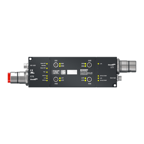
Page 17: Cabling
Mounting and cabling Cabling 3.2.1 Connector overview Fig. 5: EP7402-0057 Connectors Name Function Connector type Tightening torque M8 socket 0.4 Nm Digital input/outputs [} 22] M8 socket 0.4 Nm M8 socket 0.4 Nm M8 socket 0.4 Nm M8 socket, b-coded 0.4 Nm Motor connection [} 21] M8 socket, b-coded 0.4 Nm... -
Page 18: Supply Voltages And Ethercat
EtherCAT Tx + white EtherCAT Rx + blue EtherCAT Rx - orange EtherCAT Tx - green/yellow grey black : 24 V blue brown : 24 V The wire colors apply to cables of the type ZK7314-3xxx-Axxx. See chapter Accessories [} 47]. Version: 1.0 EP7402-0057... - Page 19 Variations in the voltage of the power supply unit must also be taken into account. Voltage drop on the supply line Conductor cross-section: 4 mm² 25 A 20 A 15 A Vert. Faktor: 0,8 cm / V 10 A Cable length (m) EP7402-0057 Version: 1.0...
- Page 20 Power output X60 Fig. 8: M8 socket Contact Function Description Core color Control voltage Brown Peripheral voltage White GND to U Blue GND to U Black The core colors apply to cables of the type ZK2020-3xxx. See chapter Accessories [} 47]. Version: 1.0 EP7402-0057...
-
Page 21: Motors
Wire color Function brown Motor phase U white Motor phase V blue Brake output black Motor phase W grey Connection example Pin 1 Pin 2 Pin 4 Brake Brake Pin 3 Pin 5 Fig. 10: Motor connection example EP7402-0057 Version: 1.0... -
Page 22: Digital Input/Outputs
Digital sensor, 2-wire connection to channel A 24 V Pin 1 DIO A Pin 4 Fig. 12: Digital sensor, 2-wire connection Digital sensor, 3-wire connection to channel A 24 V Pin 1 DIO A Pin 4 Pin 3 Fig. 13: Digital sensor, 3-wire connection Version: 1.0 EP7402-0057... -
Page 23: Commissioning
ð The LEDs next to X70 indicate whether both supply voltages are present: "24 V U " "24 V U " ð The "L/A" LED next to X70 lights up or flashes, depending on the state of the EtherCAT Master. EP7402-0057 Version: 1.0... -
Page 24: Step 2: Twincat Configuration
Commissioning 4.1.2 Step 2: TwinCAT configuration 1. Integrate EP7402-0057 into a TwinCAT project. (Quick start guide) ð A dialog box appears: 2. Click "Cancel" to close the dialog box. 3. Reset EP7402 to the factory settings: Change the value of the CoE parameter 1011:01 to 1684107116 Version: 1.0... -
Page 25: Step 3: Basic Parameters
Step 3: Basic parameters Open the “CoE – Online” tab. Set the parameters as described below. Leave the default value for all other parameters. Example parameters for a servo motor from Beckhoff: AM8111-0F20-0000 [} 45] 4.1.3.1 Index 8020 “STM Motor Settings Ch. 1”... - Page 26 8023:14 „Sensorless offset scaling“ Set this parameter to 80. 8023:19 “Rampup velocity” Unit: °/s (degrees per second) Set this parameter to the same value as parameter 8020:09 “Start velocity” [} 25]. 8023:21 Rampup needed switchover events Set this parameter to one. Version: 1.0 EP7402-0057...
-
Page 27: Step 4: Test Run
i: gear ratio (i = 1 if no gear unit is used) 4. Set "Enable" to 1. ð The rotor is aligned for 1 second. ð The box then attempts to turn the motor. 5. Assess the result. [} 28] EP7402-0057 Version: 1.0... - Page 28 8023:21 “Rampup needed switchover events” [} 26] Incorrect motor settings Check motor settings [} 25] Motor too weak Add a gear unit and re-calculate all parameters Especially likely when the motor makes a sound with ascending pitch. Version: 1.0 EP7402-0057...
-
Page 29: Step 5: Final Steps
2. Set the parameter 8023:12 "Velocity loop proportional gain" to 100 (Any value above zero activates the velocity controller). ð You can now control the motor with the process variables "Enable" and "Velocity". 3. Fine-tuning of the parameters [} 31] EP7402-0057 Version: 1.0... -
Page 30: Determining The "Mechanical To Electrical Ratio" Experimentally
The parameter 8020:13 “Mechanical to electrical ratio“ [} 40] is an essential parameter for the operation of EP7402-0057. You can calculate the parameter [} 26], if the number of poles and the gear ratio are known. Otherwise you must determine the parameter experimentally: 1. -
Page 31: Fine-Tuning Parameters
: parameter 80n3:11 “Velocity loop integral time” • Integral time T : CoE parameter 80n3:12 “Velocity loop proportional gain” • Parameter 80n3:13 “Feed forward gain” You can disable the velocity controller by setting the proportional gain K to zero. EP7402-0057 Version: 1.0... -
Page 32: Automatic Restart After Error
STM Controller Settings 4 Ch. n Restart after error number of repetition 80n3 STM Controller Settings 4 Ch. n Restart after error delay • n = 2 for motor channel 1 (socket X20) • n = 3 for motor channel 2 (socket X21) Version: 1.0 EP7402-0057... -
Page 33: Restoring The Delivery State
Fig. 16: Entering a restore value in the Set Value dialog Alternative restore value In some older terminals / boxes the backup objects can be switched with an alternative restore value: Decimal value: 1819238756 Hexadecimal value: 0x6C6F6164 An incorrect entry for the restore value has no effect. EP7402-0057 Version: 1.0... -
Page 34: Decommissioning
Disposal In order to dispose of the device, it must be removed. In accordance with the WEEE Directive 2012/19/EU, Beckhoff takes back old devices and accessories in Germany for proper disposal. Transport costs will be borne by the sender. Return the old devices with the note "for disposal" to: Beckhoff Automation GmbH &... -
Page 35: Troubleshooting
When an error occurs, the output stage of the corresponding channel is disabled until you reset the channel: Set the output variable “Reset” to 1 and back to 0. Warnings and errors are indicated via the diagnosis variables [} 36]. EP7402-0057 Version: 1.0... -
Page 36: Diagnosis Bits
[} 9] is usually much lower than the thermal limit The calculated I T value has ex- Channel n amplifier over- of the amplifier. ceeded the error threshold: load I2T error (Continued on next page) Version: 1.0 EP7402-0057... - Page 37 Increase the parameter “Start The velocity is too low. velocity” (CoE index 80n0:09 [} 40]) to make sure that the motor will not run at too low a ve- locity. Especially likely when the motor makes a sound with ascending pitch. EP7402-0057 Version: 1.0...
-
Page 38: Application Notes
1. Map the I2T value to one of the “Info data” variables in “STM Synchron info data Channel n”. CoE index 80n2 “STM Features“ [} 41]. 2. Monitor the “Info data” variable in a scope project. ð This enables to recognize irregularities. Example scope recording Version: 1.0 EP7402-0057... -
Page 39: Coe Objects
8033 STM Controller Settings 4 Ch. 2 [} 42] F000 Modular Device Profile F008 Code word F010 Module Profile List F081 Download revision F600 STM Device Diag data F80F STM Vendor data [} 43] F900 STM Info data [} 43] EP7402-0057 Version: 1.0... -
Page 40: Object Descriptions
T value exceeds this threshold, the “Channel n overload I2T error” bit is set. The motor is switched torqueless. Motor thermal time T limit monitoring: Thermal time constant. 0.1 s UINT constant The thermal time constant can be found in the motor datasheet. Version: 1.0 EP7402-0057... - Page 41 • “Motor amplifier I T load” = 12 • “Motor dc current” = 13 • “Motor back EMF” = 17 • “Motor restart counter” = 18 • “Internal temperature” = 101 • “Motor supply voltage” = 104 EP7402-0057 Version: 1.0...
- Page 42 If this parameter is zero, the motor will be switched off immediately after a commutation error in nominal operation. Restart after error de- This parameter determines the time span between a commuta- UINT 1000 tion error and the automatic restart. See also subindex 25. Version: 1.0 EP7402-0057...
-
Page 43: Information Objects
Index F900: STM Info data Access rights: read only Subindex Name Description Unit Data type Default (hex) value Internal temperature Internal temperature °C SINT Motor supply voltage Current value of the peripheral voltage U 0.01 V UINT EP7402-0057 Version: 1.0... -
Page 44: Standard Objects
Hardware revision String Refer to Firmware and hardware versions [} 7]. Index 100A Software version Access rights: read only Subindex Name Description Unit Data type Value (hex) Software Version Firmware revision Refer to Firmware and hardware versions [} 7]. Version: 1.0 EP7402-0057... - Page 45 Motor thermal time constant 8023:11 Velocity loop integral time 8023:12 Velocity loop proportional gain 8023:14 Align power 8023:15 Align duration 1000 8023:16 Rampup power 8023:18 Rampup duration 8023:19 Rampup velocity 2000 8023:21 Rampup needed switchover events 8023:22 Commutation threshold EP7402-0057 Version: 1.0...
-
Page 46: General Operating Conditions
(ph-Value > 12) > 40°C: not resistant Acetic acid not resistant Argon (technical clean) resistant • resistant: Lifetime several months • non inherently resistant: Lifetime several weeks • not resistant: Lifetime several hours resp. early decomposition Version: 1.0 EP7402-0057... -
Page 47: Accessories
ZB8801-0001 Torque cable key for M8 / wrench size 9 for ZB8801-0000 ZB8802-0003 Assembly tool for B23 connectors Further accessories Further accessories can be found in the price list for fieldbus components from Beckhoff and online at https://www.beckhoff.com. EP7402-0057 Version: 1.0... -
Page 48: Version Identification Of Ethercat Devices
Production lot/batch number/serial number/date code/D number The serial number for Beckhoff IO devices is usually the 8-digit number printed on the device or on a sticker. The serial number indicates the configuration in delivery state and therefore refers to a whole production batch, without distinguishing the individual modules of a batch. - Page 49 • IP67: EtherCAT Box • Safety: TwinSafe • Terminals with factory calibration certificate and other measuring terminals Examples of markings Fig. 17: EL5021 EL terminal, standard IP20 IO device with serial/ batch number and revision ID (since 2014/01) EP7402-0057 Version: 1.0...
- Page 50 Appendix Fig. 18: EK1100 EtherCAT coupler, standard IP20 IO device with serial/ batch number Fig. 19: CU2016 switch with serial/ batch number Fig. 20: EL3202-0020 with serial/ batch number 26131006 and unique ID-number 204418 Version: 1.0 EP7402-0057...
- Page 51 Fig. 22: EP1908-0002 IP67 EtherCAT Safety Box with batch number/ date code 071201FF and unique serial number 00346070 Fig. 23: EL2904 IP20 safety terminal with batch number/ date code 50110302 and unique serial number 00331701 Fig. 24: ELM3604-0002 terminal with unique ID number (QR code) 100001051 and serial/ batch number 44160201 EP7402-0057 Version: 1.0...
-
Page 52: Beckhoff Identification Code (Bic)
8.4.1 Beckhoff Identification Code (BIC) The Beckhoff Identification Code (BIC) is increasingly being applied to Beckhoff products to uniquely identify the product. The BIC is represented as a Data Matrix Code (DMC, code scheme ECC200), the content is based on the ANSI standard MH10.8.2-2016. - Page 53 Example of composite information from item 1 to 4 and 6. The data identifiers are marked in red for better display: An important component of the BIC is the Beckhoff Traceability Number (BTN, item no. 2). The BTN is a unique serial number consisting of eight characters that will replace all other serial number systems at Beckhoff in the long term (e.g.
-
Page 54: Support And Service
Beckhoff's branch offices and representatives Please contact your Beckhoff branch office or representative for local support and service on Beckhoff products! The addresses of Beckhoff's branch offices and representatives round the world can be found on her internet pages: http://www.beckhoff.com You will also find further documentation for Beckhoff components there. - Page 56 More Information: www.beckhoff.com/ep7402-0057/ Beckhoff Automation GmbH & Co. KG Hülshorstweg 20 33415 Verl Germany Phone: +49 5246 9630 info@beckhoff.com www.beckhoff.com...
Need help?
Do you have a question about the EP7402-0057 and is the answer not in the manual?
Questions and answers