
Subscribe to Our Youtube Channel
Related Manuals for Beckhoff EP4174-0002


Summary of Contents for Beckhoff EP4174-0002
- Page 1 Documentation EP4174-0002 EtherCAT Box with configurable analog outputs Version: 1.1.0 Date: 2018-12-06...
-
Page 3: Table Of Contents
Power Connection ...................... 21 3.2.4 Power cables ........................ 24 3.2.5 Power cable conductor losses M8 ................... 26 3.2.6 EP4174-0002 - Signal connection ................... 27 UL Requirements.......................... 28 ATEX notes ............................. 30 3.4.1 ATEX - Special conditions .................... 30 3.4.2 BG2000-0000 - EtherCAT Box protection enclosure............ 31 3.4.3... - Page 4 Table of contents Version: 1.1.0 EP4174-0002...
-
Page 5: Foreword
The TwinCAT Technology is covered, including but not limited to the following patent applications and patents: EP0851348, US6167425 with corresponding applications or registrations in various other countries. ® EtherCAT is registered trademark and patented technology, licensed by Beckhoff Automation GmbH, Germany. Copyright © Beckhoff Automation GmbH & Co. KG, Germany. -
Page 6: Safety Instructions
All the components are supplied in particular hardware and software configurations appropriate for the application. Modifications to hardware or software configurations other than those described in the documentation are not permitted, and nullify the liability of Beckhoff Automation GmbH & Co. KG. Personnel qualification This description is only intended for trained specialists in control, automation and drive engineering who are familiar with the applicable national standards. -
Page 7: Documentation Issue Status
The module features are continuously improved and developed further. Modules having earlier production statuses cannot have the same properties as modules with the latest status. However, existing properties are retained and are not changed, so that older modules can always be replaced with new ones. Documentation EP4174-0002 Version Firmware Hardware 1.1.0... -
Page 8: Product Overview
• digital outputs with 0.5 or 2 A output current • analog inputs and outputs with 16 bit resolution • Thermocouple and RTD inputs • Stepper motor modules XFC (eXtreme Fast Control Technology) modules, including inputs with time stamp, are also available. Version: 1.1.0 EP4174-0002... -
Page 9: Fig. 2 Ethercat Box With M8 Connections For Sensors/Actuators
EtherCAT, which is available for download from our website (www.beckhoff.com) under Downloads. EtherCAT XML Device Description You will find XML files (XML Device Description Files) for Beckhoff EtherCAT modules on our web- site (www.beckhoff.com) under Downloads, in the Configuration Files area. -
Page 10: Ep4174-0002 - Introduction
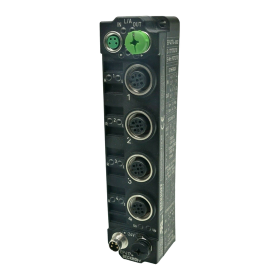
Fig. 4: EP4174-0002 EtherCAT Box with four configurable analog outputs The EP4174-0002 EtherCAT Box has four analog outputs which can be individually parameterized, so that they generate signals either in the -10 to +10 V range or the 0/4…20 mA range. The voltage or output current is fed to the process level, electrically isolated with a resolution of 15 bit (default). -
Page 11: Ep4174-0002 - Technical Data
Product overview EP4174-0002 - Technical data Technical data EP4174-0002 Fieldbus EtherCAT Fieldbus connection 2 x M8 socket (green) Number of outputs M12 sockets Connection outputs [} 27] Signal type Configurable: 0…+10 V -10…+10 V 0…20 mA 4…20 mA Load > 5 kΩ | < 500 Ω Resolution 16 bit (including sign) Conversion time < 4 ms... -
Page 12: Ep4174 - Status Leds
Power supply Display Meaning the power supply voltage, Us, is not present green illuminated the power supply voltage, Us, is present the power supply voltage, Up, is not present green illuminated The power supply voltage, Up, is present Version: 1.1.0 EP4174-0002... -
Page 13: Ep4174-0002 - Process Image
Product overview EP4174-0002 - Process image Fig. 6: EP4174-0002 - Process image AO Outputs Channel 1 The data for the first analog channel can be found under AO Outputs Channel 1. AO Outputs Channel 2 to 4 The data of analog channels 2 to 4 have the same structure as those of the first channel. -
Page 14: Mounting And Connection
Installation position variable Protection class IP65, IP66, IP67 (conforms to EN 60529) when screwed together Dimensions app. 126 x 30 x 26.5 mm app. 126 x 60 x 26,5 mm (H x W x D) app. 150 x 60 x 26.5 mm (without 7/8", B17) Version: 1.1.0 EP4174-0002... -
Page 15: Fixing
The mounting rail ZS5300-0011 (500 mm x 129 mm) has in addition to the M3 treads also pre-made M4 treads to fix 60 mm wide modules via their middle holes. Up to 14 narrow or 7 wide modules may be mixed mounted. EP4174-0002 Version: 1.1.0... -
Page 16: Nut Torque For Connectors
ZB8800 is also a max. torque of 0.5 Nm permissible. Fig. 9: EtherCAT Box with M8 connectors M12 connectors It is recommended to pull the M12 connectors tight with a nut torque of 0.6 Nm. Fig. 10: EtherCAT Box with M8 and M12 connectors Version: 1.1.0 EP4174-0002... -
Page 17: Additional Checks
Fig. 11: 7/8" plug connectors Torque socket wrenches Fig. 12: ZB8801 torque socket wrench Ensure the right torque Use the torque socket wrenches available by Beckhoff to pull the connectors tight (ZB8800, ZB8801-0000)! 3.1.4 Additional checks The boxes have undergone the following additional tests:... -
Page 18: Connection
• the Coupler Box (FBB-x110) has two M12 sockets Fig. 13: EtherCAT Box: M8, 30 mm housing Fig. 14: EtherCAT Box: M860 mm housing (example: EP9214) Fig. 15: Coupler Box: M12 Assignment There are various different standards for the assignment and colors of connectors and cables for Ethernet/ EtherCAT. Version: 1.1.0 EP4174-0002... - Page 19 M8 connectors were changed to the colors of EN61918 (yellow, orange, white, blue).So different color coding exists. But the electrical properties are absolutely identical. EtherCAT connector The following connectors can be supplied for use in Beckhoff EtherCAT systems. Name Connector...
-
Page 20: Ethercat - Fieldbus Leds
Status of the EtherCAT module is operational EtherCAT statuses The various statuses in which an EtherCAT module may be found are described in the Basic Sys- tem Documentation for EtherCAT, which is available for download from our website (www.beck- hoff.com) under Downloads. Version: 1.1.0 EP4174-0002... -
Page 21: Power Connection
Auxiliary voltage Up 24 V The Auxiliary voltage Up supplies the digital outputs; it can be brought in separately. If the load voltage is switched off, the fieldbus functions and the power supply and functionality of the inputs are retained. EP4174-0002 Version: 1.1.0... - Page 22 Us and Up can thus easily be transferred from EtherCAT Box to EtherCAT Box. NOTE Pay attention to the maximum permissible current! Pay attention also for the redirection of the supply voltages Us and Up, the maximum permissible current for M8 connectors of 4 A must not be exceeded! Version: 1.1.0 EP4174-0002...
-
Page 23: Fig. 19 Ep92X4-0023, Connectors For Power In And Power Out
EP9214 or EP9224 (with integrated data logging, see www.beckhoff.com/EP9224) is recommended. With these modules intelligent power distribution concepts with up to 2 x 16 A and a maximum of 2.5 mm²... -
Page 24: Power Cables
ZK2020-3334-0001 Angled socket, angled 0.15 m socket ZK2020-3334-0005 0.50 m ZK2020-3334-0010 1.00 m ZK2020-3334-0020 2.00 m ZK2020-3334-0050 5.00 m Further available power cables may be found in the Beckhoff catalog or on our internet pages (http:// www.beckhoff.com). Version: 1.1.0 EP4174-0002... - Page 25 Insulation resistance IEC 60 512-2 >10 Ω Current carrying capacity according to IEC 60512-3 4 A Volume resistance according to IEC 60512-2 < 5 mΩ Protection class according to IEC 60529 IP65/66/67, when screwed together Ambient temperature -30°C to +80°C EP4174-0002 Version: 1.1.0...
-
Page 26: Power Cable Conductor Losses M8
8 m power cable with 0.34 mm² cross-section has a voltage drop of 3.2 V at 4 A. EP92x4 Power Distribution Modules With EP9214 and EP9224 Power Distribution Modules intelligent concepts for voltage supply are available. Further information may be found under www.beckhoff.com/EP9224. Version: 1.1.0 EP4174-0002... -
Page 27: Ep4174-0002 - Signal Connection
Mounting and connection 3.2.6 EP4174-0002 - Signal connection 3.2.6.1 Analog voltage outputs (M12) Analog outputs, -10 to +10 V The actuator is connected via output +/- and output GND. The actuator can optionally be operated/supplied with 24 V Fig. 22: Connecting the analog voltage outputs (M12) LED indicators - meanings There is a green Run LED and a red Error LED for each channel. -
Page 28: Ul Requirements
A NEC class 2 power supply shall not be connected in series or parallel with another (class 2) power source! CAUTION CAUTION! To meet the UL requirements, the EtherCAT Box Modules must not be connected to unlimited power sources! Version: 1.1.0 EP4174-0002... -
Page 29: Fig. 26 Ul Label
To meet the UL requirements, EtherCAT Box Modules has to be operated only at an ambient temperature range of 0 to 55°C! Marking for UL All EtherCAT Box Modules certified by UL (Underwriters Laboratories) are marked with the following label. Fig. 26: UL label EP4174-0002 Version: 1.1.0... -
Page 30: Atex Notes
FF - firmware version HH - hardware version Beispiel mit Ser. Nr.: 29 10 02 01: 29 - week of production 29 10 - year of production 2010 02 - firmware version 02 01 - hardware version 01 Version: 1.1.0 EP4174-0002... -
Page 31: Bg2000-0000 - Ethercat Box Protection Enclosure
Put the cables for EtherCAT, power supply and sensors/actuators through the hole of the BG2000-0000 protection enclosure. Fig. 27: BG2000-0000, putting the cables Fix the wires for EtherCAT, power supply and sensors/actuators to the EtherCAT Box. Fig. 28: BG2000-0000, fixing the cables EP4174-0002 Version: 1.1.0... -
Page 32: Atex Documentation
Notes about operation of EtherCAT Box Modules (EPxxxx-xxxx) in potentially explo- sive areas (ATEX) Pay also attention to the continuative documentationNotes about operation of EtherCAT Box Mod- ules (EPxxxx-xxxx) in potentially explosive areas (ATEX) that is available in the download area of the Beckhoff homepage http:\\www.beckhoff.com! Version: 1.1.0 EP4174-0002... -
Page 33: Commissioning/Configuration
Beckhoff website (http://www.beckhoff.de/english/download/elconfg.htm? id=1983920606140) and installed according to the installation instructions. At the Beckhoff TwinCAT System Manager the configuration tree can be build in two different ways: • by scanning [} 33] for existing hardware (called "online") and •... -
Page 34: Fig. 31 Appending A New I/O Device (I/O Devices -> Right-Click -> Append Device
Fig. 32: Selecting the device EtherCAT • Append a new box. Fig. 33: Appending a new box (Device -> right-click -> Append Box...) • In the dialog that appears select the desired box (e.g. EP2816-0008), and confirm with OK. Version: 1.1.0 EP4174-0002... -
Page 35: Fig. 34 Selecting A Box (E.g. Ep2816-0008)
Commissioning/Configuration Fig. 34: Selecting a Box (e.g. EP2816-0008) Fig. 35: Appended Box in the TwinCAT tree EP4174-0002 Version: 1.1.0... -
Page 36: Configuration Via Twincat
EtherCAT device type Comment Here you can add a comment (e.g. regarding the system). Disabled Here you can deactivate the EtherCAT device. Create symbols Access to this EtherCAT slave via ADS is only available if this checkbox is activated. Version: 1.1.0 EP4174-0002... -
Page 37: Fig. 38 Ethercat Tab
Indicates the configuration of the process data. The input and output data of the EtherCAT slave are represented as CANopen process data objects (PDO). The user can select a PDO via PDO assignment and modify the content of the individual PDO via this dialog, if the EtherCAT slave supports this function. EP4174-0002 Version: 1.1.0... -
Page 38: Fig. 39 Process Data Tab
(not selected and greyed out), this indicates that the input is excluded from the PDO assignment. In order to be able do select a greyed out PDO, the currently selected PDO has to be deselected first. Version: 1.1.0 EP4174-0002... - Page 39 (CoE) or Servo drive over EtherCAT protocol. This tab indicates which download requests are sent to the mailbox during startup. It is also possible to add new mailbox requests to the list display. The download requests are sent to the slave in the same order as they are shown in the list. EP4174-0002 Version: 1.1.0...
-
Page 40: Fig. 40 Startup Tab
(CoE) protocol. This dialog lists the content of the object directory of the slave (SDO upload) and enables the user to modify the content of an object from this list. Details for the objects of the individual EtherCAT devices can be found in the device-specific object descriptions. Version: 1.1.0 EP4174-0002... -
Page 41: Fig. 41 Coe - Online Tab
The Update list button updates all objects in the displayed list Auto Update If this check box is selected, the content of the objects is updated automatically. Advanced The Advanced button opens the Advanced Settings dialog. Here you can specify which objects are displayed in the list. EP4174-0002 Version: 1.1.0... -
Page 42: Fig. 42 Advanced Settings
Offline If this option button is selected, the list of the objects included in the object - via EDS file directory is read from an EDS file provided by the user. Online tab Fig. 43: Online tab Version: 1.1.0 EP4174-0002... - Page 43 A carrier signal is available at the port, but the port is closed. File Access over EtherCAT Download With this button a file can be written to the EtherCAT device. Upload With this button a file can be read from the EtherCAT device. EP4174-0002 Version: 1.1.0...
-
Page 44: Object Overview
EtherCAT XML Device Description The display matches that of the CoE objects from the EtherCAT XML Device Description. We rec- ommend downloading the latest XML file from the download area of the Beckhoff website and in- stalling it according to installation instructions. - Page 45 [} 56] 801F:01 R0 Calibration Offset 0x0000 (0 801F:02 R0 Calibration Gain 0x4000 (16384 801F:03 R1 Calibration Offset 0x0000 (0 801F:04 R1 Calibration Gain 0x4000 (16384 801F:05 R2 Calibration Offset 0x0000 (0 801F:06 R2 Calibration Gain 0x4000 (16384 EP4174-0002 Version: 1.1.0...
- Page 46 F010:04 SubIndex 004 0x00000190 (400 Subindex AO Range Settings 0x04 (4 F800:0 [} 51] F800:01 Output type Ch1 0x0000 (0 F800:02 Output type Ch2 0x0000 (0 F800:03 Output type Ch3 0x0000 (0 F800:04 Output type Ch4 0x0000 (0 Version: 1.1.0 EP4174-0002...
-
Page 47: Object Description And Parameterization
EtherCAT XML Device Description The display matches that of the CoE objects from the EtherCAT XML Device Description. We rec- ommend downloading the latest XML file from the download area of the Beckhoff website and in- stalling it according to installation instructions. - Page 48 327 ms (32767/100) for the output value to change from the maximum value (32767) to the default value in the event of a fault. 8000:15 User calibration offset User calibration: Offset INT16 0x0000 (0 8000:16 User calibration gain User calibration: Gain UINT16 0x4000 (16384 Version: 1.1.0 EP4174-0002...
- Page 49 327 ms (32767/100) for the output value to change from the maximum value (32767) to the default value in the event of a fault. 8010:15 User calibration offset User calibration: Offset INT16 0x0000 (0 8010:16 User calibration gain User calibration: Gain UINT16 0x4000 (16384 EP4174-0002 Version: 1.1.0...
- Page 50 327 ms (32767/100) for the output value to change from the maximum value (32767) to the default value in the event of a fault. 8020:15 User calibration offset User calibration: Offset INT16 0x0000 (0 8020:16 User calibration gain User calibration: Gain UINT16 0x4000 (16384 Version: 1.1.0 EP4174-0002...
- Page 51 Output signal range for channel 2 (values see channel 1) UINT16 0x0000 (0 F800:03 Output type Ch3 Output signal range for channel 3 (values see channel 1) UINT16 0x0000 (0 F800:04 Output type Ch4 Output signal range for channel 4 (values see channel 1) UINT16 0x0000 (0 EP4174-0002 Version: 1.1.0...
-
Page 52: Objects For Regular Operation
Index (hex) Name Meaning Data type Flags Default 1008:0 Device name Device name of the EtherCAT slave STRING EP4174-0002 Index 1009 Hardware version Index (hex) Name Meaning Data type Flags Default 1009:0 Hardware version Hardware version of the EtherCAT slave... - Page 53 Subindex 004 4. allocated RxPDO (contains the index of the associated UINT16 0x1603 RxPDO mapping object) (5635 Index 1C13 TxPDO assign Index (hex) Name Meaning Data type Flags Default 1C13:0 TxPDO assign PDO Assign Inputs UINT8 0x00 (0 EP4174-0002 Version: 1.1.0...
- Page 54 Shift too short counter Number of occasions that the interval between SYNC0 UINT16 0x0000 (0 and SYNC1 event was too short (DC mode only) 1C32:20 Sync error The synchronization was not correct in the last cycle BOOLEAN 0x00 (0 (outputs were output too late; DC mode only) Version: 1.1.0 EP4174-0002...
-
Page 55: Profile-Specific Objects (0X6000-0Xffff)
0x4000 (16384 Index 801E AO internal data Ch.2 Index (hex) Name Meaning Data type Flags Default 801E:0 AO internal data Ch.2 UINT8 0x01 (1 801E:01 DAC raw value Raw value of the D/A converter UINT16 0x0000 (0 EP4174-0002 Version: 1.1.0... - Page 56 Modular device profile General information for the modular device profile UINT8 0x02 (2 F000:01 Module index dis- Index distance of the objects of the individual channels UINT16 0x0010 (16 tance F000:02 Maximum number of Number of channels UINT16 0x0004 (4 modules Version: 1.1.0 EP4174-0002...
-
Page 57: Restoring The Delivery State
Double-click on SubIndex 001 to enter the Set Value dialog. Enter the value 1684107116 in field Dec or the value 0x64616F6C in field Hex and confirm with OK. All backup objects are reset to the delivery state. EP4174-0002 Version: 1.1.0... - Page 58 Fig. 45: Entering a restore value in the Set Value dialog Alternative restore value In some older terminals / boxes the backup objects can be switched with an alternative restore value: Decimal value: 1819238756 Hexadecimal value: 0x6C6F6164 An incorrect entry for the restore value has no effect. Version: 1.1.0 EP4174-0002...
-
Page 59: Appendix
(ph-Value > 12) > 40°C: not resistant Acetic acid not resistant Argon (technical clean) resistant • resistant: Lifetime several months • non inherently resistant: Lifetime several weeks • not resistant: Lifetime several hours resp. early decomposition EP4174-0002 Version: 1.1.0... -
Page 60: Ethercat Box- / Ethercat P Box - Accessories
M12/wrench size 13, for torque wrench ZB8801-0000 ZB8801-0003 torque cable key, M12 field assembly/wrench size 13, for torque wrench ZB8801-0000 Further accessories Further accessories may be found at the price list for Beckhoff fieldbus components and at the inter- net under https://www.beckhoff.com Version: 1.1.0 EP4174-0002... -
Page 61: Support And Service
Beckhoff's branch offices and representatives Please contact your Beckhoff branch office or representative for local support and service on Beckhoff products! The addresses of Beckhoff's branch offices and representatives round the world can be found on her internet pages: http://www.beckhoff.com You will also find further documentation for Beckhoff components there. - Page 62 EtherCAT Box with M12 connections for sensors/actuators............Fig. 4 EP4174-0002..........................Fig. 5 EP4174 LEDs ..........................Fig. 6 EP4174-0002 - Process image....................Fig. 7 Dimensions of the EtherCAT Box Modules ................. Fig. 8 Mounting Rail ZS5300-000 ......................Fig. 9 EtherCAT Box with M8 connectors....................
- Page 63 List of Illustrations Fig. 45 Entering a restore value in the Set Value dialog................EP4174-0002 Version: 1.1.0...
Need help?
Do you have a question about the EP4174-0002 and is the answer not in the manual?
Questions and answers