
Subscribe to Our Youtube Channel
Related Manuals for Elcometer 205


Summary of Contents for Elcometer 205
- Page 1 Elcometer 205 Elcometer 206 • 206DL Ultrasonic Thickness Gauge Operating Instructions...
- Page 2 Elcometer Limited. All other trademarks acknowledged. Material Safety Data Sheets for the ultrasonic couplant supplied with the Elcometer 205, 206 & 206DL available as an accessory is available to download via our website : Elcometer Ultrasonic Couplant Material Safety Data Sheet: www.elcometer.com/images/MSDS/elcometer_ultrasonic_couplant.pdf...
-
Page 3: Table Of Contents
CONTENTS Section Page About your gauge ..............3 Quick-start . - Page 4 APPENDICES Transducers ..............39 Condition and preparation of surfaces .
-
Page 5: About Your Gauge
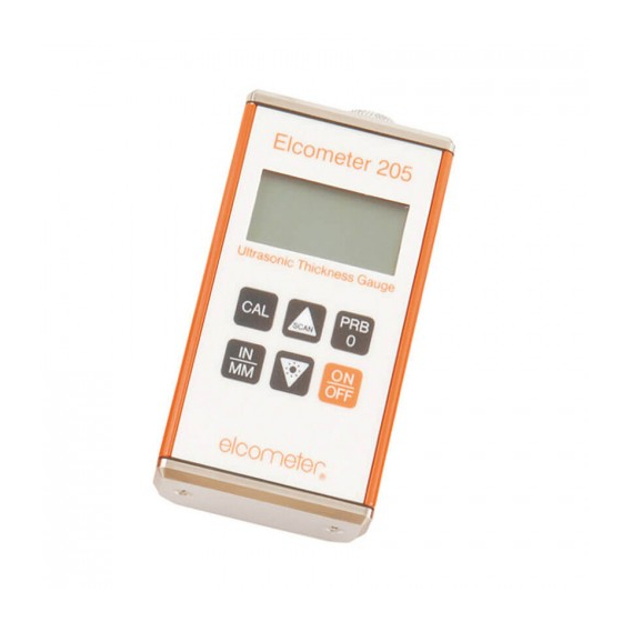
The Elcometer 205 is the basic model. • The Elcometer 206 includes all features of the 205 plus differential mode, an alarm and data output. • The Elcometer 206DL model includes all the features of the Elcometer 206 model plus a data-logging (memory) facility which allows readings to be stored in batches before being downloaded to a computer. - Page 6 1.1 STANDARDS The Elcometer 205, 206 & 206DL can be used in accordance with the following International Standards ASTM E 797, EN 14127 & EN 15317. 1.2 WHAT THIS BOX CONTAINS • Elcometer 205, 206 or 206DL Gauge • Bottle of couplant •...
- Page 7 SCAN DIFF SEND SEND Figure 1. Elcometer 205 - 206 - 206DL 1.3 FEATURES OF THE GAUGE : Identifies the minimum thickness over a large area while moving the transducer over the CAN MODE surface. While the transducer is in contact with the material being measured the smallest value is held in...
-
Page 8: Quick-Start
100 readings. Batches may be transferred to a PC using supplied software. To maximise the benefits of your new Elcometer Ultrasonic Thickness Gauge, please take some time to read these Operating Instructions. Do not hesitate to contact Elcometer or your Elcometer supplier if you have any questions. -
Page 9: Getting Started
To fit or replace batteries: 7. Locate battery compartment cover (Figure 2) at top of gauge. Elcometer 206 Elcometer 208 8. Unscrew battery compartment cover. 9. Referring to battery polarity instructions on rear of gauge, insert batteries into gauge ensuring correct polarity. - Page 10 The transducer connects to the gauge via the attached cable, and two coaxial connectors. When using transducers manufactured by Elcometer, the orientation of the dual coaxial Figure 3. Typical transducer connectors is not critical; either plug may be fitted to either socket.
- Page 11 3.3 THE KEYPAD ELCOMETER 205 (6 BUTTONS) AND 206 (9 BUTTONS) Press to switch the gauge on or off. When switching off, the gauge retains all of its settings. If the gauge is idle for 5 minutes, it will switch itself off.
- Page 12 a) Press and hold when switching the gauge on to switch the audible beeper on or off. ALRM b) Press to toggle the alarm on or off, and to adjust the nominal thickness value. See “Alarm” on page 25. Press to toggle the DIFFERENTIAL mode on or off, and to adjust the nominal thickness value.
- Page 13 ELCOMETER 206DL Press to switch the gauge on or off. When switching off, the gauge retains all of its settings. If the gauge is idle for 5 minutes, it will switch itself off. Press to zero the gauge. See “Setting the zero point (probe-zero)” on page 16.
- Page 14 Press to send the displayed thickness measurement to an internal memory location or an external storage device via the RS232 port. SEND See “Transferring data” on page 29. The SEND key is also used to select data logging functions in the Elcometer 206DL.
- Page 15 3.4 THE DISPLAY Stability Units indicator (IN, MM (see IN/µs, below) MM/s) INMM/ s µ Thickness value/ Menu items Stability indicator One bar - no readings are being taken Less than 5 bars - reading is unstable and may be inaccurate More than 5 bars - reading is stable Refer to “Read display”...
-
Page 16: Taking A Reading
3.5 FRONT PANEL LIGHTS Green light illuminates when: • The alarm mode is active, and • the measured thickness is greater than the alarm value. Red light illuminates when: • The alarm mode is active, and • the measured thickness is less than the alarm value. 4 TAKING A READING Disclaimer: Inherent in ultrasonic thickness measurement is the possibility that the instrument will use the second echo rather than the first echo from the back surface of the material being measured while in... - Page 17 • Prepare the surface. See “Condition and preparation of surfaces” on page 42. 1. Apply couplant For the gauge to work correctly there must be no air gaps between the transducer and the surface of the material to be measured. This is achieved using a material called a couplant. Before the transducer is placed on the surface, put a small amount of the couplant supplied with the gauge on the surface of the material.
-
Page 18: Setting The Zero Point (Probe-Zero)
Note: Occasionally, a small film of couplant will be drawn out between the transducer and the surface as the transducer is removed. When this happens, the gauge may perform a measurement through this couplant film, resulting in a measurement that is larger or smaller than it should be. This phenomenon is obvious when one thickness value is observed while the transducer is in place, and another value is observed after the transducer is removed. - Page 19 4. Press the transducer against the probe-disc, making sure that the transducer is flat against the surface (Figure 5). The display should show some thickness value, and nearly all the bars of the stability indicator should be illuminated. Elcometer 206 Elcometer 208 Figure 5. Transducer pressed against probe-disc 5.
-
Page 20: Calibration
6 CALIBRATION In order for the gauge to make accurate measurements, it must be set to the correct sound-velocity for the material being measured. Different types of material have different sound-velocities. For example, the velocity of sound through steel is 5918 m/s (about 0.233 in/µs) and the velocity of sound through aluminium is 6350 m/s (about 0.248 in/ µs). - Page 21 6.1 ONE-POINT CALIBRATION This procedure requires a sample piece of the material to be measured, the exact thickness of which is known, e.g. from having been measured by some other means. 1. Switch on the gauge. 1. Set the zero point of the gauge - see “Setting the zero point (probe-zero)” on page 16. 2.
- Page 22 6.2 TWO-POINT CALIBRATION This procedure requires that the operator has two known thickness points on the test piece that are representative of the range to be measured. 1. Set the zero point of the gauge - see “Setting the zero point (probe-zero)” on page 16. 2.
- Page 23 6.3 KNOWN VELOCITY CALIBRATION This procedure requires that the operator knows the sound-velocity of the material to be measured. A table of common materials and their sound-velocities can be found in “Sound velocities of common materials” on page 47. 1. Press ON/OFF key to switch on the gauge. 2.
-
Page 24: Set-Up Options
7 SET-UP OPTIONS 7.1 SCAN MODE Your gauge includes Scan Mode which allows it to examine a large region, searching for the thinnest point. In normal operation, the gauge performs and displays four measurements every second, which is quite adequate for single measurements. In Scan Mode, however, the gauge performs eight measurements every second, but does not display them. - Page 25 4. Press SEND key to switch scan mode on or off. 5. Press MODE key when finished. 7.2 DIFFERENTIAL MODE (Elcometer 206 and 206DL only) Your gauge includes Differential Mode which allows it to display the positive or negative difference from an entered nominal value.
- Page 26 To switch differential mode on/off and enter the value: Elcometer 206 Elcometer 206DL 1. Switch on the gauge. 1. Switch on the gauge. 2. Press the DIFF key. 2. Press MODE key to activate features and The gauge will display DIFF OFF or DIFF settings.
- Page 27 7.3 ALARM (Elcometer 206 and 206DL only) The Alarm feature of the Elcometer 206 and 206DL allows the user to set an audible and visual alarm when taking measurements. If the alarm is switched on, the green light on the front panel of the gauge is illuminated. If the measurement falls below the value set by the user, a red light shows on the front panel of the gauge and the beeper is sounded (if it is switched on).
- Page 28 To set alarm value and switch alarm on Elcometer 206 Elcometer 206DL 1. Switch on the gauge. 1. Switch on the gauge. 2. Press ALRM key to toggle the status of the 2. Press MODE key to activate features and alarm until the gauge displays: settings.
- Page 29 AUTO - backlight automatically illuminates while the gauge is making a measurement and switches off after several seconds (to conserve battery life). To set backlight mode Elcometer 205/206 Elcometer 206DL 1. Switch on the gauge. 1. Press ON/OFF key to switch on the gauge.
-
Page 30: Transferring Readings To A Computer
Readings can be transferred from the Elcometer 206 and Elcometer 206DL to a computer. The Elcometer 206 will transfer readings as they are taken. The Elcometer 206DL will transfer readings as they are taken and also transfer the contents of its memory. -
Page 31: Using The Data Logger
9 USING THE DATA LOGGER (Elcometer 206DL only) The Elcometer 206DL is equipped with a data logging feature. This is a valuable reporting gauge for inspection purposes. It increases efficiency by reducing the time it takes to manually record the measurements during the inspection process. - Page 32 4. Press the UP / DOWN arrow keys to scroll to the batch (1-10) that will be used. 5. Press the SEND key once again to select the batch. The display will flash FILE F-04 (or the selected batch). 6. Press the MEM key, to access the memory locations in the batch selected. The display will flash the current memory location (L007, L039, etc.), followed by the status of the memory location.
- Page 33 If the memory location is currently full, the display will flash the FuLL symbol. 2. Press the CLR key to delete the contents of the memory location. The display will flash the memory location (L011, L099, etc.) and the CLr symbol. 3.
- Page 34 9.5 DELETING CONTENTS OF ALL BATCHES 1. Press ON/OFF key to switch on the gauge. 2. Immediately press the CLR key. The display will show CLr? 3. Press CLR key once again to clear all batches.
- Page 35 9.6 TRANSFERRING DATA TO A COMPUTER At the end of the inspection process, or end of the day, the user can transfer the readings in the memory of the gauge to a computer. TRANSFERRING ONE BATCH 1. Connect the gauge to a computer and start the data transfer software - see “Transferring readings to a computer”...
-
Page 36: Storage
This will prevent damage to the gauge in the event of malfunction of the batteries. 11 MAINTENANCE The Elcometer 205/206/206DL is designed to give many years reliable service under normal operating and storage conditions. The transducer will wear with repeated use. Transducer life depends on the number of measurements taken and the manner in which readings are taken. -
Page 37: Technical Specification
The gauge does not contain any user-serviceable components. In the unlikely event of a fault, the gauge should be returned to your local Elcometer supplier or directly to Elcometer. The warranty will be invalidated if the instrument has been opened. -
Page 38: Spares
13 SPARES The following consumables, replacement and optional items are available from your local Elcometer supplier or direct from Elcometer. Type Description Sales Part No. Consumable 120 ml (4 oz) Ultrasonic couplant T92015701 Consumable 120 ml (4 oz) High temperature T92015874X ultrasonic couplant, 343°C (650°F) -
Page 39: Related Equipment
Additionally, Elcometer Limited warrants transducers and accessories against such defects for a period of 90 days from receipt by the end user. If Elcometer Limited receives notice of such defects during the warranty period, Elcometer Limited will either, at its option, repair or replace products that prove to be defective. - Page 40 15.2 Obtaining service during warranty period If your hardware should fail during the warranty period, contact Elcometer Limited and arrange for servicing of the product. Retain proof of purchase in order to obtain warranty service.
-
Page 41: Transducers
15.3 After the warranty period If your hardware should fail after the warranty period, contact Elcometer Limited for details of the services available, and to arrange for non-warranty service. APPENDIX A. TRANSDUCERS Your gauge is capable of performing measurements on a wide range of materials, from various metals to glass and plastics. - Page 42 Additionally, care must be taken when performing a ‘Calibration to Known Thickness’ with a high temperature application - see “Measuring hot surfaces” on page 43. A.5 Selecting the correct transducer Elcometer have a complete range of transducers to meet your requirements, including: • A range of frequencies and sizes...
- Page 43 • The measurement range • The type of material to be tested • The design of the transducer probe type For full details of the Elcometer range of transducers contact your local Elcometer supplier, or visit the Elcometer website www.elcometer.com...
-
Page 44: Condition And Preparation Of Surfaces
APPENDIX B. CONDITION AND PREPARATION OF SURFACES The shape and roughness of the test surface are of paramount importance when carrying out ultrasonic thickness testing. Rough, uneven surfaces may limit the penetration of ultrasound through the material, and result in unstable, and therefore unreliable, measurements. The surface being measured should be clean, and free of any small particles, rust, or scale. -
Page 45: Application Notes
APPENDIX C. APPLICATION NOTES C.1 Measuring tubing When measuring a piece of pipe to determine the thickness of the pipe wall, orientation of the transducers is important. If the diameter of the pipe is larger than approximately 100 mm (4”), measurements should be made with the transducer oriented so that the gap in the wearface is perpendicular (at right angles) to the long axis of the pipe. - Page 46 (~200°F), the change in sound-velocity of the material being measured starts to have a noticeable effect upon the accuracy of ultrasonic measurement. At such elevated temperatures, it is recommended that the user perform a calibration procedure (see “Calibration” on page 18) on a sample piece of known thickness, which is at, or near, the temperature of the material to be measured.
-
Page 47: Data Transfer Software
APPENDIX D. DATA TRANSFER SOFTWARE Software is available which allows data to be transferred from an Elcometer 206/206DL to a PC. Presently Elcometer supplies ElcoMaster. The Elcometer 206 gauge is supplied without any software but ElcoMaster is available as a free download from the Elcometer website www.elcometer.com. - Page 48 To set-up other types of communications software Elcometer 206 Elcometer 206DL 1. Start the communications software. 1. Start the communications software. 2. Configure the software using the following 2. Configure the software using the following parameters: parameters: Data Bits - 8, Parity - None, Stop Bits - 1, Data Bits - 8, Parity - None, Stop Bits - 1, Baud Rate 1200.
-
Page 49: Sound Velocities Of Common Materials
APPENDIX E. SOUND VELOCITIES OF COMMON MATERIALS Material Sound-velocity (m/s) Sound-velocity (in/µs) Aluminium 6350 0.250 Bismuth 2184 0.086 Brass 4394 0.173 Cadmium 2769 0.109 Cast Iron 4572 0.180 (Approximate) Constantan 5232 0.206 Copper 4674 0.184 Epoxy Resin 2540 0.100 (Approximate) German Silver 4750 0.187... - Page 50 Material Sound-velocity (m/s) Sound-velocity (in/µs) Plexiglas 2692 0.106 Polystyrene 2337 0.092 Porcelain 5842 0.230 (Approximate) 2388 0.094 Quartz Glass 5639 0.222 Rubber, Vulcanised 2311 0.091 Silver 3607 0.142 Steel 5918 0.233 Steel, Stainless 5664 0.223 Stellite 6985 0.275 (Approximate) Teflon 1422 0.056 3327...
Need help?
Do you have a question about the 205 and is the answer not in the manual?
Questions and answers