Table of Contents
Advertisement
Advertisement
Table of Contents

Related Manuals for Elcometer CG60DL


Summary of Contents for Elcometer CG60DL
- Page 1 Model CG60 Model CG60DL Corrosion Gauge Operating Instructions...
- Page 2 (electronic, mechanical, magnetic, optical, manual or otherwise) without the prior written permission of Elcometer Limited. A copy of this Instruction Manual is available for download on our Website via www.elcometer.com. Doc.No. TMA-0498 Issue 01...
-
Page 3: Table Of Contents
Measurement - Recording your readings (CG60DL only) ........ -
Page 4: About Your Gauge
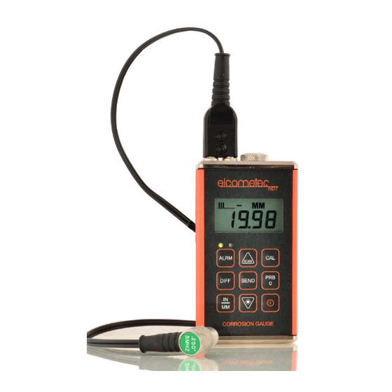
The Model CG60 and CG60DL Corrosion Gauges are handheld gauges for fast and accurate measurement of material thickness. The Model CG60 and CG60DL are both capable of measuring the thickness of various materials with accuracy as high as ± 0.1 mm (± 0.004"). The principal advantage of ultrasonic measurement over traditional methods is that ultrasonic measurements can be performed with access to only one side of the material being measured. - Page 5 1.2 WHAT THIS BOX CONTAINS Model CG60 Gauge or Model CG60DL Gauge, Bottle of couplant, Battery, 2 x, Carrying case, Test certificate, Operating instructions, CD with data transfer and data collection software - CG60DL only, RS232 cable and USB to Serial converter CG60DL only Note: The box does not include a transducer;...
-
Page 6: The Keypad
2 THE KEYPAD 2.0.1 Model CG60 keypad The ON/OFF key switches the gauge on or off. To switch the gauge on, press the ON/OFF key. The gauge will perform a brief test by illuminating all of the segments in the display. After one second, the display will show the internal software version number and then the measurement mode ‘P-E’... - Page 7 The UP arrow/SCAN key has two functions. When the Model CG60 is in CAL or ALARM mode, press this key to increase numeric values on the display. An auto-repeat function is built in, so that when the key is held down, numeric values increment at an increasing rate.
- Page 8 See “Calibration” on page 17. When the Model CG60DL is taking readings, press the MODE key to adjust the features and settings of the MODE gauge (alarm, scan, units, P-E/E-E, backlight, and beeper). The MODE key is used in conjunction with the...
- Page 9 See “Measurement options” on page 23. The CLR key is used with the data-logging feature of the Model CG60DL. This key clears the contents of an entire batch, or individual memory locations. The CLR key is also used to send an obstruct message (ObSt) to an individual memory location.
-
Page 10: Getting Started
3 GETTING STARTED 3.1 FITTING BATTERIES The Model CG60/CG60DL may be used with dry cell batteries or rechargeable batteries. 2 x LR6 (AA) alkaline batteries are supplied in the kit. When the battery voltage is low the entire display will start to flash. When Battery this occurs the batteries should be replaced. - Page 11 When you purchased your gauge you should have also purchased a suitable transducer for your application. If you have not yet done so, refer to “Transducers” on page 38, which will help you identify the correct transducer type. Alternatively contact Elcometer NDT, your local Elcometer NDT supplier or visit www.elcometerndt.com.
-
Page 12: The Display
To switch on or off, press the on/off key The gauge will switch off automatically after 5 minutes of inactivity. 4 THE DISPLAY The display segments for the Model CG60 and the Model CG60DL are shown in Figure 5. INMM/ s µ... - Page 13 Refer to “Read display” on page 22 and “Transducers” on page 38 for information on how to achieve a stable measurement. When the + symbol is on and blinking, this indicates that the Model CG60DL is currently INMM/ s µ...
- Page 14 Display segment Information displayed When the MM symbol is on, the gauge is displaying a thickness value in millimetres. The µ maximum value displayed is 25.40 millimetres (MM). When the IN symbol is on, the gauge is displaying a thickness value in inches. The INMM/ s µ...
-
Page 15: Measurement Modes
4.1 FRONT PANEL LIGHTS Green light illuminates when: • The alarm mode is active, and • the measured thickness is greater than the alarm value. Red light illuminates when: • The alarm mode is active, and • the measured thickness is less than the alarm value. 5 MEASUREMENT MODES Your gauge has two measurement modes, Pulse-Echo and Echo-Echo. - Page 16 This combination of using both modes is ideal for very detailed inspections. To select measurement mode: Model CG60 Model CG60DL 1. Press ON/OFF key to switch on the gauge. 1. Press ON/OFF key to switch on the gauge. 2. Press DUAL/MULTI key to toggle between the 2.
-
Page 17: Setting Up The Gauge
6 SETTING UP THE GAUGE 6.1 TRANSDUCER - ZEROING Setting the zero point of the gauge is important for the same reason that setting the zero on a mechanical micrometer is important. If the zero point of the gauge is not set correctly, all of the measurements the gauge makes will be in error by some fixed number. - Page 18 4. Make sure that the gauge is in P-E (pulse-echo mode): Model CG60 Model CG60DL 1. Press DUAL/MULTI toggle 1. Press MODE key. measurement mode to P-E. 2. Press SEND key to toggle measurement mode to P-E. 3. Press MODE key to confirm selection.
- Page 19 If the gauge is not set to the correct sound-velocity, all of the measurements the gauge makes will be erroneous by some fixed percentage. There are three methods of calibrating the Model CG60 and Model CG60DL gauges: One-point : This is the simplest and most commonly used calibration procedure - optimising CALIBRATION linearity over large ranges.
- Page 20 6.2.1 One-point calibration This procedure requires a sample piece of the material to be measured, the exact thickness of which is known, e.g. from having been measured by some other means. 1. Press ON/OFF key to switch on the gauge. 1.
- Page 21 6.2.2 Two-point calibration This procedure requires that the operator has two known thickness points on the test piece that are representative of the range to be measured. 1. Set the zero point of the gauge - see “Setting up the gauge” on page 15. 2.
- Page 22 6.2.3 Known velocity calibration This procedure requires that the operator knows the sound-velocity of the material to be measured. A table of common materials and their sound-velocities can be found in “Sound velocities of common materials” on page 46. 1. Press ON/OFF key to switch on the gauge. 2.
-
Page 23: Measurement - Taking Readings
7 MEASUREMENT - TAKING READINGS Disclaimer Inherent in ultrasonic thickness measurement is the possibility that the instrument will use the second echo rather than the first echo from the back surface of the material being measured while in standard pulse-echo mode. - Page 24 7.2 PROCEDURE 7.2.1 Apply couplant For the gauge to work correctly there must be no air gap between the transducer and the surface of the material to be measured. This is achieved using a couplant. Before the transducer is placed on the surface, put a small amount of couplant supplied with the gauge on the surface of the material.
-
Page 25: Measurement Options
Although the gauge excels at making single point measurements, it is sometimes desirable to examine a larger region, searching for the thinnest point. The Model CG60 and CG60DL include a feature, called Scan Mode, which allows it to do just that. - Page 26 Selection of scan mode is now complete. 8.2 ALARM The Alarm feature of the Model CG60 and CG60DL allows the user to set an audible and visual alarm when taking measurements. If the alarm is switched on, the green light on the front panel of the gauge is illuminated. If the measurement falls below the value set by the user, a red light shows on the front panel of the gauge and the beeper is sounded if it is switched on.
- Page 27 8.2.1 To switch beeper on/off Elcometer CG60 Elcometer CG60DL 1. While the gauge is off, press and hold down 1. Press ON/OFF key to switch on the gauge. ALRM key. 2. Press MODE key to activate features and 2. Press ON/OFF key to switch on the gauge.
- Page 28 8.2.2 To set alarm value and switch alarm on Elcometer CG60 Elcometer CG60DL 1. Press ON/OFF key to switch on the gauge. 1. Press ON/OFF key to switch on the gauge. 2. Press ALRM key to toggle the status of the 2.
- Page 29 (to conserve battery life). 8.3.1 To set backlight mode Model CG60 Model CG60DL 1. Press ON/OFF key to switch on the gauge. 1. Press ON/OFF key to switch on the gauge. 2. Press DOWN key to toggle the status of the 2.
-
Page 30: Measurement - Recording Your Readings (Cg60Dl Only)
9 MEASUREMENT - RECORDING YOUR READINGS (CG60DL ONLY) The Model CG60DL is equipped with a data logging feature. This is a valuable reporting gauge for inspection purposes. It increases efficiency by reducing the time it takes to manually record the measurements during the inspection process. - Page 31 • CLr in the display, indicating that the memory location is empty • ObSt (obstruct) in the display, indicating that a measurement could not be obtained 7. Press the UP / DOWN arrow keys to advance to the desired memory location. 9.2 STORING A MEASUREMENT 1.
- Page 32 9.4 DELETING CONTENTS OF AN ENTIRE BATCH The user may require the contents of an entire batch to be cleared of all measurements. This would allow the user to start a new list of measurements starting at memory location L001, for example. The procedure is outlined in the following steps: 1.
-
Page 33: Transferring Readings To A Computer
Readings can be transferred from the Model CG60 and Model CG60DL to a computer. The Model CG60 will transfer readings as they are taken. The Model CG60DL will transfer readings as they are taken and also transfer the contents of its memory. - Page 34 10.1.1 Transferring data Model CG60 After taking a measurement, press the SEND key to send the measurement to the computer. Model CG60DL Follow the instructions in “Measurement options” on page 23 10.1.2 Transferring one batch 1. Connect the gauge to a computer and start the data transfer software - see “Transferring readings to a computer”...
-
Page 35: Storage
6. Press the MEM key to exit the data logging functions. 11 STORAGE The Model CG60/CG60DL gauge has a Liquid Crystal Display. If the display is heated above 50°C (120°F) it may be damaged. This can happen if the gauge is left in a car parked in strong sunlight. -
Page 36: Maintenance
The gauge does not contain any user-serviceable components. In the unlikely event of a fault, the gauge should be returned to your local Elcometer NDT supplier or directly to Elcometer. The warranty will be invalidated if the instrument has been opened. - Page 37 Sound-velocity range: 1250 m/s to 10 000 m/s (0.0492 in/μs to 0.3937 in/μs) Physical Weight: 295 g (10 oz) including batteries Size: 63.5 mm x 120.6 mm x 31.5 mm (2.5" x 4.5" x 1.24") Operating temperature: -30°C to 50°C (-20°F to 120°F) (depending upon climatic conditions) Case: Extruded aluminium body, Nickel plated aluminium end caps 13.2 Keypad...
-
Page 38: Warranty
Additionally, Elcometer NCT warrants transducers and accessories against such defects for a period of 90 days from receipt by the end user. If Elcometer NDT receives notice of such defects during the warranty period, Elcometer NDT will either, at its option, repair or replace products that prove to be defective. The warranty will be invalidated if the instrument has been opened. - Page 39 14.2 Obtaining service during warranty period If your hardware should fail during the warranty period, contact Elcometer NDT and arrange for servicing of the product. Retain proof of purchase in order to obtain warranty service. For products that require servicing, Elcometer NDT may use one of the following methods: •...
-
Page 40: Spares
15 SPARES The Model CG60/CG60DL gauge is complete with all the items required to get started and take measurements (transducers must be ordered separately). Over the life of the gauge replacement items may be required. The following replacement and optional items are available from your local Elcometer NDT supplier or directly from Elcometer. - Page 41 The best measurement condition is one where sufficient ultrasonic energy is sent into the material being measured such that a strong, stable echo is received by the gauge. Several factors affect the strength of ultrasound as it travels. These are outlined below: 16.1 INITIAL SIGNAL STRENGTH The stronger a signal is to begin with, the stronger its return echo will be.
- Page 42 Additionally, care must be taken when performing a ‘Calibration to Known Thickness’ with a high temperature application - see “Measuring hot surfaces” on page 44. 16.5 SELECTING THE CORRECT TRANSDUCER Elcometer NDT have a complete range of transducers to meet your requirements, including: • A range of frequencies and sizes •...
- Page 43 Material being Transducer type Mode Notes measured required High penetration PULSE-ECHO Cast iron - 1MHz to 5MHz Larger diameters offer greater plastics (P-E) transducer. penetration power because of the castings Cast aluminium - 10MHz crystal size, for difficult to measure transducer.
- Page 44 Material being Transducer type Mode Notes measured required Thin materials PULSE-ECHO High frequency The higher frequencies provide (P-E) transducers are required; greater resolution and a lower typically the 7.5MHz and minimum thickness rating overall. 10MHz models with extra resolution. High temperature PULSE-ECHO Special 2.25MHz and 5 Echo-echo mode will eliminate error...
-
Page 45: Condition And Preparation Of Surfaces
17 CONDITION AND PREPARATION OF SURFACES The shape and roughness of the test surface are of paramount importance when carrying out ultrasonic thickness testing. Rough, uneven surfaces may limit the penetration of ultrasound through the material, and result in unstable, and therefore unreliable, measurements. The surface being measured should be clean, and free of any small particles, rust, or scale. - Page 46 If the diameter of the pipe is larger than approximately 100 mm (4”), measurements should be made with the transducer oriented so that the gap in the wearface is perpendicular (at right angles) to the long axis of the pipe. If the diameter of the pipe is small, two measurements should be performed, one with the wearface gap perpendicular to the long axis of the pipe, another with the gap parallel to the long axis of the pipe (Figure 8).
- Page 47 When performing measurements on hot surfaces, it may also be necessary to use a high-temperature transducer. It is recommended that the transducer be left in contact with the surface for as short a time as needed to acquire a stable measurement. While the transducer is in contact with a hot surface, it will begin to heat up, and through thermal expansion and other effects, may adversely affect the accuracy of measurements.
-
Page 48: Sound Velocities Of Common Materials
calibrated for mild steel pipe and measures through both materials, the actual coating thickness will appear to be 2.5 times thicker than it actually is, as a result of the differences in sound-velocity. The error can be eliminated by using the echo-echo mode to perform measurements for applications such as these. - Page 49 Sound Sound Sound Sound Material Material velocity (m/s) velocity (in/µs) velocity (m/s) velocity (in/µs) Iron 5893 0.232 3327 0.131 Lead 2159 0.085 Titanium 6096 0.240 Magnesium 5791 0.228 Tungsten 5334 0.210 Mercury 1448 0.057 Water 1473 0.058 Nickel 5639 0.222 Zinc 4216 0.166...
Need help?
Do you have a question about the CG60DL and is the answer not in the manual?
Questions and answers