Table of Contents
Advertisement
Advertisement
Table of Contents

Related Manuals for Elcometer 207


Summary of Contents for Elcometer 207
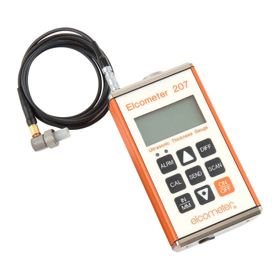
- Page 1 Elcometer 207 • 207DL Ultrasonic Thickness Gauge Operating Instructions...
- Page 2 (electronic, mechanical, magnetic, optical, manual or otherwise) without the prior written permission of Elcometer Instruments Ltd. A copy of this Instruction Manual is available for download on our Website via www.elcometer.com/ downloads.
-
Page 3: Table Of Contents
CONTENTS Section Page About your gauge ..............2 Quick-start . -
Page 4: About Your Gauge
The Elcometer 207/207DL Precision Ultrasonic Thickness Gauge are world beating products. With the purchase of this gauge you now have access to the worldwide service and support network of Elcometer. For more information visit our website at www.elcometer.com. 1 ABOUT YOUR GAUGE The Elcometer 207/207DL Precision Ultrasonic Thickness Gauges are handheld gauges for fast and accurate measurement of the thickness of thin materials. - Page 5 To maximise the benefits of your new Elcometer Ultrasonic Thickness Gauge, please take some time to read these Operating Instructions. Do not hesitate to contact Elcometer or your Elcometer supplier if you have any questions. 1.2 FEATURES OF THE GAUGE : Allows measurement of coated materials without having to remove the coating.
-
Page 6: Quick-Start
: Identifies the minimum thickness over a large area while moving the transducer over the CAN MODE surface. While the transducer is in contact with the material being measured the smallest value is held in memory and displayed when scanning is complete. : Allows the user to set a target so that an audible and visual alarm operates when taking LARM measurements. -
Page 7: Getting Started
3 GETTING STARTED 3.1 FITTING BATTERIES Your gauge may be used with dry cell batteries or rechargeable batteries. Battery 2 x LR6 (AA) alkaline batteries are supplied in the kit. compartment cover To fit or replace batteries: 1. Locate battery compartment cover at top of gauge. 2. - Page 8 The transducer must be used correctly in order for the gauge to produce accurate, reliable measurements. The Elcometer 207 and the Elcometer 207DL operate only with the 15 MHz precision ultrasonic transducer. The diagram shows the side view of the 15 MHz, single-element delay line transducer.
- Page 9 3.3 THE KEYPAD ELCOMETER 207 Functions For more information see Press to switch the gauge on or off. " When switching off, the gauge retains all of its settings. " If the gauge is idle for 5 minutes, it will switch itself off.
- Page 10 Functions For more information see a) Press and hold during gauge switch on to toggle the audible beeper on or off. b) Press to toggle the alarm on or off, and to adjust the nominal thickness “Alarm” on page 22. value.
- Page 11 ELCOMETER 207DL Functions For more information see Press to switch the gauge on or off. " When switching off, the gauge retains all of its settings. " If the gauge is idle for 5 minutes, it will switch itself off.
- Page 12 Functions For more information see a) Decreases values on the display (press and hold to change values quickly). b) When MODE key has been pressed, scrolls through the various features and settings of the gauge. c) When MEM key has been pressed, scrolls through the various files, memory locations, and functions of the data logger.
- Page 13 3.4 THE DISPLAY Stability indicator (see below) Units (IN, MM, IN/µs, MM/s) INMM/ s µ Thickness value/Menu items Stability indicator One bar - no readings are being taken Less than 5 bars - reading is unstable and may be inaccurate More than 5 bars - reading is stable Refer to “Read display”...
- Page 14 3.5 FRONT PANEL LIGHTS Green light illuminates when: • The alarm mode is active, and • the measured thickness is greater than the alarm value. Red light illuminates when: • The alarm mode is active, and • the measured thickness is less than the alarm value.
-
Page 15: Taking A Reading
4 TAKING A READING Disclaimer: Inherent in ultrasonic thickness measurement is the possibility that the instrument will use the second echo rather than the first echo from the back surface of the material being measured while in standard pulse-echo mode. This may result in a thickness reading which is TWICE what it should be. The responsibility for proper use of the instrument and recognition of these types of phenomenon rests solely with the user of the instrument. - Page 16 3. Read display If six or seven bars of the stability indicator are showing, the display will be reading the correct thickness of the material directly beneath the transducer. If the stability indicator has fewer than five bars showing, or the numbers on the display seem erratic, check to make sure that there is an adequate film of couplant beneath the transducer, and that the transducer is seated flat against the material.
-
Page 17: Calibration
5 CALIBRATION In order for the gauge to make accurate measurements, it must be set to the correct sound-velocity for the material being measured. Different types of material have different sound-velocities. For example, the velocity of sound through steel is 5918 m/s (about 0.233 in/µs) and the velocity of sound through aluminium is 6350 m/s (about 0.248 in/ µs). - Page 18 5.1 KNOWN THICKNESS CALIBRATION This procedure requires a sample piece of the material to be measured, the exact thickness of which is known, e.g. from having been measured by some other means. 1. Switch on the gauge. 2. Apply couplant to the sample piece. 3.
- Page 19 Note: At any time during the gauge calibration procedure (IN, MM, IN/µs, or M/s flashing in the display), pressing the SCAN key (207) or CLR key (207DL) will restore the gauge to the factory default sound-velocity for steel, 5918 m/s (0.233 in/µs).
-
Page 20: Set-Up Options
6 SET-UP OPTIONS 6.1 MEASUREMENT MODE The gauge has three measurement modes; echo-echo, interface-echo and automatic. : The gauge has the ability to read thin metals from 0.15 mm to 10.14 mm (0.006" to 0.399"). ECHO The echo-echo mode also allows the user to measure the thickness of metals that have been previously coated or painted on the surface. - Page 21 6.1.1 To select measurement mode Elcometer 207 Elcometer 207DL 1. Press ON/OFF key to switch on the gauge. 1. Press ON/OFF key to switch on the gauge. 2. Press UP arrow key to switch between the 2. Press MODE key to activate features and measurement modes.
- Page 22 When the transducer loses contact with the surface for more than a second the gauge will display the lowest value it found. To switch scan mode on/off: Elcometer 207 Elcometer 207DL 1. Switch on the gauge.
- Page 23 Your gauge includes Differential Mode which allows it to display the positive or negative difference from an entered nominal value. To switch differential mode on/off and enter the value: Elcometer 207 Elcometer 207DL 1. Switch on the gauge. 1. Switch on the gauge.
- Page 24 Use of the red light and beeper improves the speed and efficiency of the inspection process by eliminating constant viewing of the reading displayed. To switch beeper on/off Elcometer 207 Elcometer 207DL 1. While the gauge is off, press and hold down 1.
- Page 25 To set alarm value and switch alarm on Elcometer 207 Elcometer 207DL 1. Switch on the gauge. 1. Switch on the gauge. 2. Press ALRM key to toggle the status of the 2. Press MODE key to activate features and alarm until the gauge displays: settings.
- Page 26 AUTO - backlight automatically illuminates while the gauge is making a measurement and switches off after several seconds (to conserve battery life). 6.5.1 To set backlight mode Elcometer 207 Elcometer 207DL 1. Switch on the gauge. 1. Press ON/OFF key to switch on the gauge.
-
Page 27: Transferring Readings To A Computer
The Elcometer 207DL will transfer readings as they are taken and also transfer the contents of its memory. A data transfer cable is used to connect the gauge to the computer. This cable is supplied with an Elcometer 207DL, but must be ordered separately for an Elcometer 207 - see “Spares” on page 35. - Page 28 Excel Link, EDCS or EDCS communications software 1. Start the communications software (EDTS , EDCS or EDCS 2. Select gauge type Elcometer 207 or 207DL. To set-up other types of communications software Elcometer 207 Elcometer 207DL 1. Start the communications software.
-
Page 29: Using The Data Logger
8 USING THE DATA LOGGER (Elcometer 207DL only) The Elcometer 207DL is equipped with a data logging feature. This is a valuable reporting gauge for inspection purposes. It increases efficiency by reducing the time it takes to manually record the measurements during the inspection process. - Page 30 4. Press the UP / DOWN arrow keys to scroll to the batch (1-10) that will be used. 5. Press the SEND key once again to select the batch. The display will flash FILE F-04 (or the selected batch). 6. Press the MEM key, to access the memory locations in the batch selected. The display will flash the current memory location (L007, L039, etc.), followed by the status of the memory location.
- Page 31 If the memory location is currently full, the display will flash the FuLL symbol. 2. Press the CLR key to delete the contents of the memory location. The display will flash the memory location (L011, L099, etc.) and the CLr symbol. 3.
- Page 32 8.5 DELETING CONTENTS OF ALL BATCHES 1. Press ON/OFF key to switch on the gauge. 2. Immediately press the CLR key. The display will show CLr? 3. Press CLR key once again to clear all batches. 8.6 TRANSFERRING DATA TO A COMPUTER At the end of the inspection process, or end of the day, the user can transfer the readings in the memory of the gauge to a computer.
- Page 33 8.7 PRINTING A BATCH The user may wish to print an individual batch to a serial printer or computer. A batch can, very simply, be printed to a communications program on a PC (i.e. Elcometer EDTS Excel Link, EDCS or EDCS ), and then printed.
-
Page 34: Storage
6. Press SEND, once again, to select the batch to be printed. The display will flash FILE F-05 (or the batch selected). 7. Press the UP / DOWN arrow keys to scroll to the flashing Prnt F-05 (or the batch selected), or LISt (tape printer). -
Page 35: Maintenance
At www.elcometer.com 11 RELATED EQUIPMENT Elcometer produces a wide range of material thickness gauges and associated inspection equipment. Users of the Elcometer 207 and 207DL may also benefit from the following Elcometer products: • Elcometer range of ultrasonic gauges •... -
Page 36: Technical Specification
12 TECHNICAL SPECIFICATION Range: 0.15 mm to 25.4 mm (0.006" to 1.000") Resolution: 0.002 mm (0.0001") Accuracy: ±0.002 mm (±0.0001"), depends on material and conditions Sound-velocity range: 1250 m/s to 10 000 m/s (0.0492 in/µs to 0.3937 in/µs) Weight: 295 g (10 oz) including batteries Size: 63.5 mm x 120.6 mm x 31.5 mm (2.5"... -
Page 37: Spares
13 SPARES The following consumables, replacement and optional items are available from your local Elcometer supplier or direct from Elcometer. Type Description Sales Part No. Consumable 120 ml (4 oz) Ultrasonic couplant T92015701 Consumable 60 ml (2 oz) High temperature ultrasonic couplant... -
Page 38: Warranty
Additionally, Elcometer Instruments Ltd. warrants transducers and accessories against such defects for a period of 90 days from receipt by the end user. If Elcometer Instruments Ltd. receives notice of such defects during the warranty period, Elcometer Instruments Ltd. will either, at its option, repair or replace products that prove to be defective. -
Page 39: Transducers
• Refund the purchase price. 14.3 AFTER THE WARRANTY PERIOD If your hardware should fail after the warranty period, contact Elcometer Instruments Ltd. for details of the services available, and to arrange for non-warranty service. 15 TRANSDUCERS Your gauge is capable of performing measurements on a wide range of materials, from various metals to glass and plastics. - Page 40 15.1 INITIAL SIGNAL STRENGTH The stronger a signal is to begin with, the stronger its return echo will be. Initial signal strength is largely a factor of the size of the ultrasound emitter in the transducer. A large emitting area will send more energy into the material being measured than a small emitting area.
-
Page 41: Condition And Preparation Of Surfaces
15.4 TEMPERATURE OF THE MATERIAL When it is necessary to measure on surfaces that are exceedingly hot, special high-temperature transducers may be necessary. Additionally, care must be taken when performing a ‘Calibration to Known Thickness’ with a high temperature application - see “Measuring hot surfaces” on page 40. 16 CONDITION AND PREPARATION OF SURFACES The shape and roughness of the test surface are of paramount importance when carrying out ultrasonic thickness testing. -
Page 42: Application Notes
17 APPLICATION NOTES 17.1 MEASURING TUBING When measuring a piece of tubing for wall thickness, it may prove beneficial to have multiple delay lines with different radiuses for different tubing diameters. The delay lines can be easily radiused by placing a piece of emery cloth around the tubing and moving the transducer back and forth until a radius has formed on the tip of the delay line. - Page 43 17.3 MEASURING LAMINATED MATERIALS The density (and therefore sound-velocity) of laminated materials may vary considerably from one piece to another. Some laminated materials may even exhibit noticeable changes in sound-velocity across a single surface. The only way to reliably measure such materials is by performing a calibration procedure on a sample piece of known thickness.
-
Page 44: Data Transfer Software
18 DATA TRANSFER SOFTWARE Software is available which allows data to be transferred from an Elcometer 207/207DL to a PC. Elcometer supplies three types of data transfer software: • Elcometer Data Transfer Software (EDTS Excel Link) • Elcometer Data Collection Software (EDCS) •... -
Page 45: Sound Velocities Of Common Materials
EDCS is available from your local Elcometer supplier or directly from Elcometer. 18.3 SOFTWARE INSTALLATION EDTS Excel Link, EDCS and EDCS are compatible with computers operating on Windows™ 95 (service pack 1), 98, ME, NT, 2000 and XP. The installation conforms to the standard Windows method using ‘Setup.exe’... - Page 46 Material Sound-velocity (m/s) Sound-velocity (in/µs) Lead 2159 0.085 Magnesium 5791 0.228 Mercury 1448 0.057 Nickel 5639 0.222 Nylon 2591 0.102 (Approximate) Paraffin 2210 0.087 Platinum 3962 0.156 Plexiglas 2692 0.106 Polystyrene 2337 0.092 Porcelain 5842 0.230 (Approximate) 2388 0.094 Quartz Glass 5639 0.222 Rubber, Vulcanised...
Need help?
Do you have a question about the 207 and is the answer not in the manual?
Questions and answers