
Related Manuals for Elcometer 2300 Series


Summary of Contents for Elcometer 2300 Series
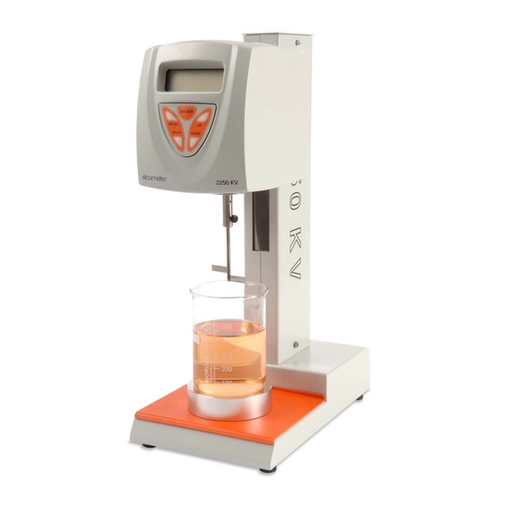
- Page 1 Elcometer 2300 Rotational Viscometer ViscosityMaster Software Operating Instructions...
- Page 2 The Elcometer Rotary Viscometer has been tested in accordance with EU regulations governing Electro-magnetic compliance and it meets the required directives. Note: Gauge readings may be affected if the unit is operated within a radio frequency electromagnetic strength of greater than 3 V/m.
-
Page 3: Table Of Contents
ONTENTS CONTENTS Section Page A: V ECTION ISCOMETER About your Viscometer ..........1 Getting started . - Page 4 ONTENTS 14.2 Uninstalling ViscosityMaster..........31 14.3 Starting ViscosityMaster .
-
Page 5: Section A: V Iscometer
Our products cover all aspects of coating inspection, from development through application to post application inspection. The Elcometer Rotary Viscometer is a world beating product. With the purchase of this product you now have access to the worldwide service and support network of Elcometer. For more information visit our website at www.elcometer.com... - Page 6 BOUT YOUR ISCOMETER 1.2 What the box contains • Viscometer head • Column with head mounting bracket • Spindles L1 to L4 or R2 to R7 (R2 to R7 shown in illustration) • Base • Box spanner tool • Hexagonal wrench •...
- Page 7 • Shear rate (RV2 models only) • Shear stress (RV2 models only) Your Elcometer Rotary Viscometer is packed in a cardboard and foam package. Please ensure that this packaging is disposed of in an environmentally sensitive manner. Consult your local Environmental Authority for further guidance.
-
Page 8: Getting Started
ETTING STARTED 2 GETTING STARTED This section of the instructions is intended for first-time users of the Elcometer Rotary Viscometer. It contains information on the parts and controls of the instrument and advice on safe use of the equipment. When you have finished reading this section you will be ready to start using your Elcometer Rotary Viscometer. -
Page 9: Assembling The Viscometer
ETTING STARTED 2.2 Assembling the Viscometer To assemble your Viscometer: 1. Remove the nut from the bottom end of the column. 2. Fit the column onto the base with the slot facing towards the front. 3. Fit the nut onto the bottom of the column and tighten using the box spanner supplied with your Viscometer. -
Page 10: Rear Connections
ETTING STARTED 2.3 Rear connections Power Power supply on/off socket switch PT 100 RS 232 probe interface socket 2.4 Control panel Your Viscometer is controlled using the five buttons on the control panel on the front of the Viscometer head. Enter setup screen ENTER Increase /... -
Page 11: Configuring Your Viscometer
ETTING STARTED 2.5 Configuring your Viscometer Switch on the Viscometer by pressing the power on/off switch at the rear of the Viscometer head. A welcome message will be displayed for a period of two seconds. The contents of the message will depend upon the model, software version and language setting: V2-R v4.3 English... - Page 12 ETTING STARTED The temperature units selection screen will appear: Temperature Units Celsius Using the [UP] or [DOWN] buttons, select the temperature units, Celsius or Fahrenheit. Press [ENTER] to confirm your selection. The mode selection screen will appear: Computer mode Using the [UP] or [DOWN] buttons, select the required mode, Printer or Computer. Press [ENTER] to confirm your selection.
-
Page 13: Fitting The Spindle Guard
ETTING STARTED 2.6 Fitting the spindle guard The spindle guard supplied with your Viscometer has two functions: • It provides physical protection for spindle types L and R. • It allows accurate measurements to be taken with the large spindles (L1 and R1, R2, R3). Use of the spindle guard with spindles other than the L1 and R1, R2, R3 is optional. -
Page 14: Spindle Types
ETTING STARTED 2.7 Spindle types Used for Spindle type Use with measurement of (included with Elcometer 2300 RV1-L Low to medium Viscometer) Elcometer 2300 RV2-L viscosity fluids (included with Elcometer 2300 RV1-R Medium to high Viscometer) Elcometer 2300 RV2-R viscosity fluids... -
Page 15: Fitting The Spindle
2.9 Caution The Elcometer Rotary Viscometer has been manufactured with your safety in mind. However, improper use can result in damage to the machine. Please observe the precautions discussed in these operating instructions. -
Page 16: Using Your Viscometer
SING YOUR ISCOMETER 3 USING YOUR VISCOMETER This section describes how to take measurements with your Viscometer. The instructions apply to RV1 Viscometers and to RV2 Viscometers under manual operation. For additional instructions on using RV2 Viscometers interfaced to a PC, refer to “ViscosityMaster Software” on page 30. 3.1 Before you start 1. -
Page 17: Starting A Measurement
SING YOUR ISCOMETER 3.3 Starting a measurement 1. Press [START] to start the measurement. Stable flow conditions are reached quickly and the viscosity readings on the display of the Viscometer can be considered correct within a few seconds (depending on the selected speed and the viscosity of the sample). -
Page 18: After Use
RINTING TEST RESULTS and temperature) should always be used to test this type of product and additional parameters should be recorded such as the time elapsed before first measurement, sampling interval, etc. 3.5 After use Clean the instrument and spindle. Always remove the spindle from the instrument before cleaning. -
Page 19: Using The Optional Accessories
The adaptor for small sample volumes allows precise measurement of the viscosity of small sample volumes (8 ml to 13 ml). The adaptor is suitable for use with all models of the Elcometer Rotary Viscometer. There are two types of this adaptor: •... -
Page 20: Adaptor For Low Viscosity Samples
The adaptor for low viscosity samples allows precise measurement of the viscosity of low viscosity samples (16 ml to 18 ml), both Newtonian and non Newtonian. The adaptor is suitable for use with all models of the Elcometer Rotary Viscometer. There are two types of this adaptor: •... -
Page 21: Adaptor For Helical Movement
The adaptor is suitable for use with all models of the Elcometer Rotary Viscometer. The adaptor moves the Viscometer head slowly up and down. This movement causes the spindle to... - Page 22 SING THE OPTIONAL ACCESSORIES 5. Slide the second ring clamp onto the column. 6. Insert the rod of the Viscometer head through the hole in the mounting bracket on the drive mechanism and rotate the mounting bracket lever to lock the Viscometer head in position.
-
Page 23: Spindle Selection Tables
PINDLE SELECTION TABLES 6 SPINDLE SELECTION TABLES 6.1 L and TL Spindles (For use with RV1-L / RV2-L Viscometers). Table 1: Spindle type L Maximum measurable viscosity (mPa•s) Spindle speed (rpm) 20 000 100 000 400 000 2 000 000 12 000 60 000 240 000 1 200 000... - Page 24 PINDLE SELECTION TABLES Table 2: Spindle type TL Maximum measurable viscosity (mPa•s) Spindle speed (rpm) 10 000 100 000 200 000 6000 60 000 120 000 5000 50 000 100 000 3000 30 000 60 000 2000 20 000 40 000 1500 15 000 30 000...
-
Page 25: R And Tr Spindles (For Use With Rv1-R / Rv2-R Viscometers)
PINDLE SELECTION TABLES 6.2 R and TR Spindles (For use with RV1-R / RV2-R Viscometers) Table 3: Spindle type R Spindle Maximum measurable viscosity (mPa•s) speed (rpm) 33 300 133 300 333 300 666 600 1 300 000 3 330 000 13 300 000 20 000 80 000 200 000... - Page 26 PINDLE SELECTION TABLES Table 4: Spindle type TR Maximum measurable viscosity (mPa•s) Spindle speed (rpm) TR10 TR11 166 600 833 300 1 600 000 3 300 000 100 000 500 000 1 000 000 2 000 000 83 300 416 600 833 300 1 600 000 50 000...
-
Page 27: Lcp Spindle
PINDLE SELECTION TABLES 6.3 LCP Spindle Table 5: Spindle type LCP Maximum measurable Spindle viscosity (mPa•s) speed (rpm) RV1-L / RV2-L RV1-R / RV2-R 2000 21 333 1200 12 800 1000 10 666 6400 4266 3200 2560 2133 1600 1280 1066 Resolution 0.01 mPa•s... -
Page 28: P Series Spindles
PINDLE SELECTION TABLES 6.4 P series spindles Table 6: P series spindles for RV1-L and RV2-L Viscometers Spindle Maximum measurable viscosity (mPa•s) speed (rpm) 62 400 124 800 312 000 624 000 1 560 000 3 120 000 37 440 74 880 187 200 374 400... -
Page 29: Calibration
The Elcometer Rotary Viscometer does not contain any internal user-serviceable components. In the unlikely event of a fault, the instrument should be returned to your local Elcometer supplier or directly to Elcometer. Details of Elcometer offices around the world are given on the outside cover of these Operating... -
Page 30: Troubleshooting
ROUBLESHOOTING 9 TROUBLESHOOTING The instrument does not operate Check: • the connection to the mains electricity supply • the power on/off switch position at the rear of the Viscometer head The spindle does not rotate concentrically Check: • that the spindle is correctly adjusted to the shaft •... -
Page 31: Technical Specification
ECHNICAL SPECIFICATION 10 TECHNICAL SPECIFICATION Room temperature: 10°C to 40°C (50°F to 104°F) Relative humidity: < 80% Speeds: 0.3, 0.5, 0.6, 1, 1.5, 2, 2.5, 3, 4, 5, 6, 10, 12, 20, 30, 50, 60, 100, 200 rpm Accuracy (speed): >... -
Page 32: Spare Parts And Accessories
PARE PARTS AND ACCESSORIES 11 SPARE PARTS AND ACCESSORIES The following spare parts and accessories for your Elcometer Rotary Viscometer are available from your local supplier or direct from Elcometer: 11.1 Standard spindles Spindle set, standard, type L (L1 to L4) -
Page 33: Related Equipment
KT00230020180 12 RELATED EQUIPMENT In addition to the Elcometer Rotary Viscometer, Elcometer produces a wide range of other equipment for determining the physical characteristics of surface coatings. Users of the Elcometer 2300 may also benefit from the following Elcometer products: •... -
Page 34: Section B: V Iscosity Master Software
• Create PDF versions of your reports and e-mail direct from ViscosityMaster. 13.1 System Requirements To use the software on this CD you will need an Elcometer 2300 Rotational Viscometer, a computer and a data transfer cable. ® The software will run on PC compatible computers under Windows 98, 98SE, 2000, ME, NT and XP. -
Page 35: Uninstalling Viscositymaster
An RS232 to USB transfer cable is available which allows you to connect your Viscometer to a USB port on your computer; part number T99916716. Contact Elcometer or your local supplier for ordering details. -
Page 36: Help
If you need help with your Elcometer 2300 Rotational Viscometer, refer to the operating instructions which were included with your Viscometer. If you cannot find the answer to your question, please do not hesitate to contact Elcometer or your Elcometer supplier. -
Page 37: The User Interface
HE USER INTERFACE 15 THE USER INTERFACE The ViscosityMaster user interface is very similar to a standard Windows Explorer interface: 1. Toolbar: New, cut, copy, delete, auto, manual, stop, export, etc. 2. Explorer Window: Lists the files and folders on your PC and on your Viscometer. All data is stored in \My Documents\My ViscoMeter Data. -
Page 38: Example Data
XAMPLE DATA 16 EXAMPLE DATA When you install Elcometer ViscosityMaster software, a set of example data is loaded into your local folder; click on ‘Viscometer Data’ in the Explorer Window and then look for ‘Example Batch’ in the List Window. -
Page 39: Operating Modes
PERATING MODES 17 OPERATING MODES Your ViscosityMaster software has two operating modes; manual and automatic. • In manual mode your ViscosityMaster software records measurements as they are taken by the instrument but it does not control the operation of the Viscometer. •... - Page 40 RV1 V NSTRUCTIONS FOR ISCOMETERS 3. The Model, Spindle type, Company and Operator will already be set from ‘Preferences’ when ViscosityMaster was run for the first time. If necessary, amend these details as required. 4. Enter details in the Identifier and Notes fields. This information is used later, typically within test reports.
-
Page 41: Running A Batch
RV2 V NSTRUCTIONS FOR ISCOMETERS 18.2 Running a batch 1. Lower the Viscometer spindle into the test sample. 2. Click on ‘Manual’ and then press ‘Start’ on the Viscometer. 3. The measurements and charts will be shown in real time. 4. - Page 42 RV2 V NSTRUCTIONS FOR ISCOMETERS 2. Type a name for the batch and then press the Return key. 3. The Model, Spindle type, Company and Operator will already be set from ‘Preferences’ when ViscosityMaster was run for the first time. If necessary, amend these details as required. 4.
-
Page 43: Setting Up Processes
RV2 V NSTRUCTIONS FOR ISCOMETERS 19.2 Setting up processes In automatic mode the Viscometer is controlled using processes. Processes are groups of data which specify settings such as spindle speed, rotation duration, measurement frequency, etc. A single batch can incorporate any number of processes. 1. -
Page 44: Running A Batch
RV2 V NSTRUCTIONS FOR ISCOMETERS 19.3 Running a batch 1. Lower the Viscometer spindle into the test sample. 2. Click on ‘Automatic’. The Viscometer will start under control of ViscosityMaster and the measurements and charts will be shown in real time. 3. -
Page 45: Working With Viscometer Data
ORKING WITH ISCOMETER DATA 20 WORKING WITH VISCOMETER DATA This section describes what you can do with your Viscometer batch data once it has been downloaded into ViscosityMaster: • Viewing Measurement Data and Standard Reports • Customising report window tabs •... - Page 46 ORKING WITH ISCOMETER DATA 4. Adjust the contents of the chart using the X axis and Y axis drop down lists. 5. To zoom in to an area on the chart, use your mouse to left click and drag. To reset the zoom click on the Reset Zoom button.
-
Page 47: Customising Report Window Tabs
ORKING WITH ISCOMETER DATA 20.2 Customising report window tabs The Header, Measurements and My Reports tabs are always visible in the Report Window. All other tabs (and user defined tabs) can be added or deleted: 1. In the Explorer Window, click on Reports. 2. -
Page 48: Viewing A Custom Report
ORKING WITH ISCOMETER DATA 4. In the Report Window, click ‘New Page’ and then choose between ‘Opening’, ‘Inner’ and ‘Closing’ page types. • Opening pages: Typically used for report title page; can contain text, shapes and graphics; cannot be used to display reading data; prints first when printing a report. •... -
Page 49: Exporting Measurement Data
ORKING WITH ISCOMETER DATA 3. In the Report Window, click on My Reports tab and then select the report from the Reports drop-down list. 4. Click on a thumbnail of a report on the left side of the Report Window to view an individual page of the report. -
Page 50: Using Documents And Images
SING DOCUMENTS AND IMAGES • Sent via e-mail as an attachment Click the appropriate button in the Report Window and follow the standard Windows instructions which follow. 21 USING DOCUMENTS AND IMAGES Use ViscosityMaster to store your test notes, reports, spreadsheets and all your other test information. -
Page 51: The
HE PAGE DESIGNER 22 THE PAGE DESIGNER This section describes how to use the Page Designer - a utility built in to ViscosityMaster which allows you to create your reports: • Designing a Page • The Property Editor • The Text Editor 1. -
Page 52: Designing A Page
HE PAGE DESIGNER 22.1 Designing a Page The contents of a page are ‘Objects’ such as shapes, memos, readings, etc. To add an object to the page, choose the object in the Object Picker Window (1), move the cursor to the Page Layout Window (5) and then click and drag the object to the required size. -
Page 53: The Property Editor
HE PAGE DESIGNER 22.2 The Property Editor Precise control over the layout, attributes and content of an object is obtained by modifying the properties of the object using the Property Editor. Object properties which are adjustable using the Property Editor are listed below. The list of properties available depends upon the type of object selected (shape, memo, graphic, overview chart, etc.): Property... -
Page 54: The Text Editor
HE PAGE DESIGNER Property Description Defines name of object. Object names are displayed Name: in Object Selector Window. PageWidth (mm): Defines width of the page in mm. PageHeight (mm): Defines height of the page in mm. PageType: Defines page type; Opening, Inner or Closing. PageOrientation: Portrait (default) or Landscape. -
Page 55: Text Editor Data Field Buttons
Information added in header when creating a New Batch 23 SUPPORT For support with this software, information on the Elcometer product range and details of your local supplier, contact any of the Elcometer offices worldwide. Contact details can be found under ‘Help’... -
Page 56: Index
NDEX 24 INDEX Accessories Guard (for spindles) Overview Adaptor for helical movement Adaptor for low viscosity samples Helical movement adaptor Adaptor for small sample volume Spares Assembly (of Viscometer) Help ViscosityMaster 32, 51 Batch Creating Images, in ViscosityMaster Inner pages (ViscosityMaster) Interfaces Running Keypad... - Page 57 NDEX Printer, thermal Standards Printing Stopping the motor Printing Mode Printing test results Problems with measurements (Viscometer) Technical specifications Temperature (high) Processes, setting up (RV2) Temperature units, selecting Property editor (designing reports) Thermal printer Spares Time and Date Report page designing (ViscosityMaster) 48 Troubleshooting 13, 26 Rotation speed...
Need help?
Do you have a question about the 2300 Series and is the answer not in the manual?
Questions and answers