Queclink GV500 User Manual
Hide thumbs
Also See for GV500:
- User manual (17 pages) ,
- User manual (17 pages) ,
- User manual (17 pages)

Related Manuals for Queclink GV500


Summary of Contents for Queclink GV500
-
Page 1: User Manual
GV500 User Manual GV500 GSM/GPRS/GPS Tracker User Manual TRACGV500UM001 Revision: 1.01 http://www.queclink.com sales@queclink.com TRACGV500UM001 - 0 -... - Page 2 Furthermore, system validation of this product designed by Queclink within a larger electronic system remains the responsibility of the customer or the customer’s system integrator. All specifications supplied herein are subject to change.
-
Page 3: Table Of Contents
GV500 User Manual Contents Contents ............................2 Table Index ............................3 Figure Index ............................4 0. Revision history ..........................5 1. Introduction ........................... 6 1.1. Reference ..........................6 1.2. Terms and Abbreviations ....................6 2. Product Overview ......................... 7 2.1. Description .......................... 7 2.2. - Page 4 GV500 User Manual Table Index TABLE 1: GV500 PROTOCOL REFERENCE ..................6 TABLE 2: TERMS AND ABBREVIATIONS ..................6 TABLE 3: PART LIST ..........................7 TABLE 4: DESCRIPTION OF OBD II CONNECTIONS ..............8 TABLE 5: DEFINITION OF DEVICE STATUS AND LED ..............14 TABLE 6: COMMUNICATION PROTOCOLS LIST ................
- Page 5 GV500 User Manual Figure Index FIGURE 1. APPEARANCE OF GV500 .................... 7 FIGURE 2. THE OBD II CONNECTOR ON THE GV500 ............... 8 FIGURE 3. OPENING THE CASE ....................10 FIGURE 4. CLOSING THE CASE ....................11 FIGURE 5. SIM CARD INSTALLATION ..................12 FIGURE 6.
-
Page 6: Revision History
GV500 User Manual 0. Revision history Revision Date Author Description of change 1.00 2013-8-16 Leo LEI Initial 1.01 2014-03-19 Cid Xu Updated Introduction information; Updated the pictures; Updated 4.2 OBD II Parameters TRACGV500UM001 - 5 -... -
Page 7: Introduction
GV500 User Manual 1. Introduction The GV500 is a vehicle tracking device that plugs into a vehicle's OBD II port. It's compact design allows easy installation. Its internal OBD reader can obtain information from the vehicle's on-board computer and relay it over GPRS networks. Its built in GPS receiver has superior sensitivity and fast time to first fix. -
Page 8: Product Overview
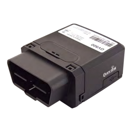
2. Product Overview 2.1. Description GV500 is based on the OBD II interface GPS vehicle tracking device, compact design and easy to install. GV500 contains an OBD II connector which complies with J1962 standard, a 10PIN USB connector, an internal GSM antenna, an internal GPS antenna and three LEDs. -
Page 9: Interface Definition
GV500 User Manual 2.3. Interface Definition The GV500 has an OBD II connector. It contains power supply and interfaces of CAN bus, K-line, L-line and J1850 bus. The sequence and definition of the OBD II connector are shown in following figure: Figure 2. -
Page 10: Getting Started
GV500 User Manual 3. Getting Started 3.1. Opening the Case Insert the triangular-pry-opener into the gap of the case as shown below, push the opener up until the case unsnapped. TRACGV500UM001 - 9 -... -
Page 11: Figure 3. Opening The Case
GV500 User Manual Figure 3. Opening the Case TRACGV500UM001 - 10 -... -
Page 12: Closing The Case
GV500 User Manual 3.2. Closing the Case The battery is glued to top cover, so before closing the case you should let the battery connector plugged in. The step of closing case is shown as following: Figure 4. Closing the Case... -
Page 13: Installing A Sim Card
GV500 User Manual 3.3. Installing a SIM Card Open the case and ensure the unit is not powered. Slide the holder right to open the SIM card. Insert the SIM card into the holder as shown below with the gold-colored contact area facing down taking care to align the cut mark. -
Page 14: Installing The Internal Backup Battery
GV500 User Manual 3.4. Installing the Internal Backup Battery Figure 6. Backup Battery Installation There is an internal backup Li-ion battery. 3.5. Device Status LED Figure 7. GV500 LED on the Case TRACGV500UM001 - 13 -... -
Page 15: Table 5: Definition Of Device Status And Led
Fast flashing GPS chip has gotten GPS info. No external power and internal battery voltage is lower (note 2) than 3.46V. GV500 is power off. No external power and internal battery voltage is Slow flashing below 3.55V External power in and internal battery is charging... -
Page 16: Obd Ii-Related Features
4. OBD II-related features 4.1. Communication Protocols GV500 could monitor the OBD II system via not only communication protocols which defined by SAE but also some special protocols. The list of protocols is shown as follow: Table 6: Communication Protocols List... - Page 17 VIN from OBD II system, because the Vehicle manufacturers are responsible for defining the data return from OBD II system. 2 - Distance Statistics: GV500 could get the distance in two cases: distance accumulated since MIL is activated and distance accumulated since DTCs were cleared.
Need help?
Do you have a question about the GV500 and is the answer not in the manual?
Questions and answers