Table of Contents
Advertisement
Quick Links
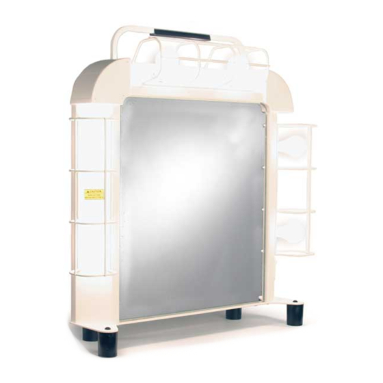
5-light 30-inch Studio
Makeup Station
C
ONTENTS
Important User Information . . . . . . . . . . . . . . . . . . . . . . . . . . .2
General . . . . . . . . . . . . . . . . . . . . . . . . . . . . . . . . . . . . . .2
Manufacturer . . . . . . . . . . . . . . . . . . . . . . . . . . . . . . . . .2
Installation . . . . . . . . . . . . . . . . . . . . . . . . . . . . . . . . . . .2
Intended Use . . . . . . . . . . . . . . . . . . . . . . . . . . . . . . . . .2
Electrical Rating . . . . . . . . . . . . . . . . . . . . . . . . . . . . . . .3
Warranty . . . . . . . . . . . . . . . . . . . . . . . . . . . . . . . . . . . . . . . . .4
Safety . . . . . . . . . . . . . . . . . . . . . . . . . . . . . . . . . . . . . . . . . . .5
Installation . . . . . . . . . . . . . . . . . . . . . . . . . . . . . . . . . . .5
General . . . . . . . . . . . . . . . . . . . . . . . . . . . . . . . . . . . . . .6
Maintenance . . . . . . . . . . . . . . . . . . . . . . . . . . . . . . . . . .6
User Instructions . . . . . . . . . . . . . . . . . . . . . . . . . . . . . . . . . . .7
Description . . . . . . . . . . . . . . . . . . . . . . . . . . . . . . . . . . .7
Lighting . . . . . . . . . . . . . . . . . . . . . . . . . . . . . . . . . . . . . .8
Electric Receptacle . . . . . . . . . . . . . . . . . . . . . . . . . . . . .9
Mirror . . . . . . . . . . . . . . . . . . . . . . . . . . . . . . . . . . . . . . .10
Counter . . . . . . . . . . . . . . . . . . . . . . . . . . . . . . . . . . . . . .10
Storage Shelf . . . . . . . . . . . . . . . . . . . . . . . . . . . . . . . . .10
Tackboard (36-inch Model Only) . . . . . . . . . . . . . . . . . .11
Accessories . . . . . . . . . . . . . . . . . . . . . . . . . . . . . . . . . .11
Required Tools . . . . . . . . . . . . . . . . . . . . . . . . . . . . . . . . . . . .11
Fasteners and Parts List . . . . . . . . . . . . . . . . . . . . . . . . . . . .12
Parts List . . . . . . . . . . . . . . . . . . . . . . . . . . . . . . . . . . . . .12
Fasteners . . . . . . . . . . . . . . . . . . . . . . . . . . . . . . . . . . . .12
Note: Please read and understand the Studio
before assembly or installation.
Note: If you need additional information about your Studio Makeup Station, contact the Wenger
Corporation using the information below.
Note: Two people must work together for some assembly steps.
Note: Because wall construction varies, wall anchors are not supplied with the Studio Makeup
Station.
©Wenger Corporation 2005
Wenger Corporation, 555 Park Drive, P.O. Box 448, Owatonna, Minnesota 55060-0448
International Installation and Owner's Manual
8-light 30-inch Studio
Makeup Station
Printed in USA 10/05
Questions? Call.....USA: 01-507-455-4100 • www.wengercorp.com
Studio
6-light 36-inch Studio
Makeup Station
Installation . . . . . . . . . . . . . . . . . . . . . . . . . . . . . . . . . . . . . . . .13
Before Starting the Assembly . . . . . . . . . . . . . . . . . . . . .13
Lighting . . . . . . . . . . . . . . . . . . . . . . . . . . . . . . . . . . . . . .14
Layout the Space . . . . . . . . . . . . . . . . . . . . . . . . . . . . . .14
Install the Mounting Bracket . . . . . . . . . . . . . . . . . . . . . .16
Install the First Makeup Station . . . . . . . . . . . . . . . . . . .18
Install Additional Makeup Stations . . . . . . . . . . . . . . . . .22
Complete the Installation . . . . . . . . . . . . . . . . . . . . . . . .22
Attach the Mirror . . . . . . . . . . . . . . . . . . . . . . . . . . . . . .23
Attach the Counter . . . . . . . . . . . . . . . . . . . . . . . . . . . . .23
Electrical Installation . . . . . . . . . . . . . . . . . . . . . . . . . . . . . . . .24
Connect the Electrical Source . . . . . . . . . . . . . . . . . . . .24
Wiring Diagram 30-inch Model . . . . . . . . . . . . . . . . . . . .26
Wiring Diagram 36-inch Model . . . . . . . . . . . . . . . . . . . .27
Maintenance . . . . . . . . . . . . . . . . . . . . . . . . . . . . . . . . . . . . . .28
Broken Mirror Replacement . . . . . . . . . . . . . . . . . . . . . .28
Lighting . . . . . . . . . . . . . . . . . . . . . . . . . . . . . . . . . . . . . .29
Cleaning . . . . . . . . . . . . . . . . . . . . . . . . . . . . . . . . . . . . .29
Replacement Parts . . . . . . . . . . . . . . . . . . . . . . . . . . . . . . . . .30
Makeup Station Main Assembly . . . . . . . . . . . . . . . . . . .30
Makeup Station Additional Parts . . . . . . . . . . . . . . . . . . .31
®
Makeup Station Installation and Owner's Manual
®
Makeup Station
International 30-inch Model
International 36-inch Model
9-light 36-inch Studio
Makeup Station
Part #187A350-01
Advertisement
Table of Contents

Subscribe to Our Youtube Channel
Related Manuals for Wenger Studio Makeup Station Series


Summary of Contents for Wenger Studio Makeup Station Series
-
Page 1: Table Of Contents
Note: Please read and understand the Studio Makeup Station Installation and Owner’s Manual before assembly or installation. Note: If you need additional information about your Studio Makeup Station, contact the Wenger Corporation using the information below. Note: Two people must work together for some assembly steps. -
Page 2: Important User Information
Wenger Corporation. Wenger Corporation does not assume any responsibility for any errors that may appear in this manual. In no event will Wenger Corporation be liable for technical or editorial omissions made herein, nor for direct, indirect, special, incidental, or consequential damages resulting from the use or defect of this manual. -
Page 3: Electrical Rating
MPORTANT NFORMATION CONTINUED LECTRICAL ATING The Studio Makeup Station outlet ratings are: Standard Lamp Load Outlet Rating W01 German Standard 5-light: 1.25 Ampere 16 Ampere (Max) 6-light: 1.5 Ampere 250 VAC 8-light: 2.0 Ampere 9-light: 2.25 Ampere W02 Japan Standard 5-light: 2.5 Ampere 15 Ampere (Max) 6-light: 3.0 Ampere... -
Page 4: Warranty
This is your sole remedy for breach of this warranty. Should you have a question or problem with any Wenger product, don’t hesitate to call, even if the product is past warranty. It’s important to us that all our customers be satisfied. -
Page 5: Safety
AFETY Throughout this manual you will find WARNINGS and CAUTIONS which are defined as follows. • WARNING means that failure to follow the instruction may result in serious injury or death. • CAUTION means that failure to follow the instruction may result in injury or damage to property. Read and understand the following Safety Instructions before installing or using the Studio Makeup Station. -
Page 6: General
WARNING Do not alter the electrical Replace any malfunctioning circuits without the electrical components only expressed permission of with components with the Wenger Corporation. same specification. CAUTION CAUTION CAUTION Replace any broken light Always disconnect power to Replace the Mirror bulbs immediately. -
Page 7: User Instructions
NSTRUCTIONS ESCRIPTION The Studio Makeup Station is intended to provide the necessary elements to apply makeup or create special visual effects. It has the following features. 1. Lighting that is bright and untainted in color. 2. An electrical outlet for makeup appliances. 3. -
Page 8: Lighting
IGHTING Light bulbs are not supplied with the Studio Makeup Station. The end user should choose the light bulb that is best suited for the Makeup Station use. For accurate color rendering, Wenger Corporation recommends either of the following. ®... -
Page 9: Electric Receptacle
NSTRUCTIONS CONTINUED IGHTING CONTINUED Refer to the illustration below describing the light switch function. This column of light is common to both Stations and is controlled by the Station to the right. If this Station is used, it is necessary to turn on the lights for this Station and the Station immediately to the right. -
Page 10: Mirror
Never strike the mirror. Never han le broken mirror with bare hands. Use Caution when replacing a broken mirror. NOTE: Refer to page 28 for instructions regarding replacing a broken mirror or call Wenger Corporation Customer Service. OUNTER • The Counter surface is matte white for light diffusion and is mar and stain resistant. The surface can withstand the operating temperatures typical of the dressing room environment. -
Page 11: Tackboard (36-Inch Model Only)
Drawer Unit — a closed drawer (not equipped with a lock) attaches below the Counter on the right hand side. It has drawer glides for smooth operation and a storage volume similar to the Storage Cubby described above. Contact Wenger Corporation for specific dimensions, installation procedures and pricing information. EQUIRED OOLS Tools required for installation are a cordless drill, a phillips screwdriver or a phillips insert bit, a 3/8"... -
Page 12: Fasteners And Parts List
ASTENERS AND ARTS The Makeup Station is shipped with all components in a single box, the main assembly, a corrugated sleeve containing the Mirror, a hardware bag, the Counter under the main assembly, the Tackboard Assembly (36-inch Model only) in a corrugated sleeve, and the Wall Mounting Bracket. ASTENERS 3/4"... -
Page 13: Installation
NSTALLATION EFORE TARTING THE SSEMBLY Before installing the Studio Makeup Station, do the following. 1. Read and understand this installation instruction completely. 2. Open all cartons and make sure each includes a Studio Makeup Station, a hardware bag, the Wall Mounting Bracket, a Tackboard (36-inch Model only), a Mirror (packaged in a corrugated sleeve) and a Counter. -
Page 14: Lighting
IGHTING Light bulbs are not supplied with the Studio Makeup Station. The end user should choose the light bulb that is best suited for the Makeup Station use. For accurate color rendering, Wenger Corporation recommends either of the following. ®... - Page 15 NSTALLATION CONTINUED AYOUT THE PACE CONTINUED * 17-1/2" for 30-inch Model (44.45 cm) ** 30" for 30-inch Model (76.20 cm) Corner 20-1/2" Minimum Distance to a Wall (52.07 cm)* Top Edge of 36"** Mounting Bracket (91.44 cm) Top Surface of 36"** Shelf (91.44 cm)
-
Page 16: Install The Mounting Bracket
NSTALLATION CONTINUED NSTALL THE OUNTING RACKET 1. Remove the Mounting Bracket from the shipping box. 2. Locate the Hardware Bag and set it aside. 3. Align the Mounting Bracket to the wall with the top edge of the Mounting Bracket on the Horizontal LIne and the centerline of the Mounting Bracket (user must mark the Bracket centerline with chalk) aligned to the Station Centerline on the wall as shown below. - Page 17 INSTALLATION CONTINUED NSTALL THE OUNTING RACKET CONTINUED 5. For walls with metal stud construction do as follows. a. Hold the Mounting Bracket in place and note the position of the studs. b. If the Mounting Bracket crosses two studs, attach the Bracket with four 14x2-inch (6 mm x 6 cm) Self-drilling Screws (supplied by end user), two in each stud.
-
Page 18: Install The First Makeup Station
NSTALLATION CONTINUED NSTALL THE IRST AKEUP TATION 1. Remove the four Flange Nuts, 3/8-16, from the hardware bag. 2. Screw (clockwise) a Flange Nut, 3/8-16, onto each each of the two Mounting Bracket Studs with the Flanges facing upward as shown below. Position the Flange Nuts so that the flange of the nut is one-half inch from the top edge of the Mounting Bracket. - Page 19 NSTALLATION CONTINUED NSTALL THE IRST AKEUP TATION CONTINUED 6. With two people working together, tilt the Makeup Station into an upright position. a. Only handle the Makeup Station by grasping the Steel Frame — do not lift or handle the Makeup Station by grasping the Light Cages or the Shelf.
- Page 20 NSTALLATION CONTINUED NSTALL THE IRST AKEUP TATION CONTINUED 7. Attach the 6-light or 5-light Makeup Station to the left-hand Mounting Bracket as follows. a. With two people working together, grasp the Makeup Station Frame WARNING and lift the Station upward. b.
- Page 21 NSTALLATION CONTINUED NSTALL THE IRST AKEUP TATION CONTINUED 8. Level the Makeup Station as follows. a. Place a Box Level across the two Counter Mounting Brackets. b. To move the left side upward, use a 9/16-inch open end wrench and turn the Left Lower Flange Nut counterclockwise and the Right Lower Flange Nut clockwise.
-
Page 22: Install Additional Makeup Stations
NSTALLATION CONTINUED NSTALL DDITIONAL AKEUP TATIONS NOTE: Always start a row with a 6-light or 5-light unit on the left end. Add additional 6-light units to the right and finish the row with a 9-light unit or a 8-light unit on the right end. 1. -
Page 23: Attach The Mirror
NSTALLATION CONTINUED TTACH THE IRROR 1. Remove the Mirror from the shipping carton and inspect for damage. CAUTION 2. With two people working together, place the Mirror against the Frame about an inch (2 cm) from the top with Mirror Flange at the bottom. Never strike the mirror. -
Page 24: Electrical Installation
Notes to the Electrician: 1. Wenger Studio Makeup Stations are supplied with conductor leads inside of 24 to 30 inches (60 cm to 75 cm) of flexible armored conduit. This is connected to a 2”x4”x2” (5 cm x 10 cm x 5 cm) connection box, with a cover. - Page 25 Cover Flexible Metal Conduit Terminal Block (Not Included) See NOTE Below Terminal Block is NOT PROVIDED by Wenger. Minimum Wire Area Capacity: 4 mm (#12 AWG) Minimum Current Capacity: 20 amps Minimum Voltage Capacity: 250 VAC Studio Makeup Station Yellow/Green, 14 AWG...
-
Page 26: Wiring Diagram 30-Inch Model
LECTRICAL NSTALLATION CONTINUED IAGRAM 30 IRING ODEL 60 or 40 Watt Surround E26 or E27 Lampholder Brown, 18 AWG Brown, 18 AWG Lt Blue, 18 AWG Lt Blue, 18 AWG Brown, 18 AWG Ground Lt Blue, 18 AWG Brown, 18 AWG Lt Blue, 18 AWG Green/Yellow, 18 AWG Note: Right-hand lights... -
Page 27: Wiring Diagram 36-Inch Model
LECTRICAL NSTALLATION CONTINUED IAGRAM 36 IRING ODEL 60 or 40 Watt Surround E26 or E27 Lampholder Brown, 18 AWG Brown, 18 AWG Lt Blue, 18 AWG Lt Blue, 18 AWG Brown, 18 AWG Ground Lt Blue, 18 AWG Brown, 18 AWG Lt Blue, 18 AWG Green/Yellow, 18 AWG Note: Right-hand lights... -
Page 28: Maintenance
AINTENANCE ROKEN IRROR EPLACEMENT CAUTION To reduce the risk of damage and injury to persons, observe the following: • Wear safety glasses and safety shoes. • Dispose of broken mirror in a safe manner. • Never handle the mirror with bare hands. •... -
Page 29: Lighting
Over tightening will strip the Pan Head Screw threads in the Frame. Pan Head Screw IGHTING For accurate color rendering, Wenger recommends either of the following replacement bulbs. ® ® • GE Reveal 60 watt or GE Reveal 40 watt incandescent bulbs or equivalent. -
Page 30: Replacement Parts
EPLACEMENT ARTS AKEUP TATION SSEMBLY NOTE: W06 - Australian/New Zealand Standard Receptacle is shown Item Description Item Description 10* Shelf, Studio Mirror Surround Assembly, Studio 11 3/8" Screw-in Connector/ Flex Conduit Mirror Assembly, Studio 12 Phillips Oval Head Screw, 8-32x3/4" Grade 2, Wedgewood Side Raceway Cover, Studio 13 Phillips Truss Head Screw, 6-32x1/2"... -
Page 31: Makeup Station Additional Parts
EPLACEMENT ARTS CONTINUED AKEUP TATION DDITIONAL ARTS Item Description Wall Mounting Bracket Tackboard Assembly (36-inch Model only) Bottom Frame Clip Self-drill Screw, 1/4-14x3/4" Phillips Head Sheet Metal Screw, #10x3/4" Flange Nut, 3/8-16 * Specify 36-inch or 30-inch Model...
Need help?
Do you have a question about the Studio Makeup Station Series and is the answer not in the manual?
Questions and answers