
Related Manuals for Emerson AMS 2140


Summary of Contents for Emerson AMS 2140
- Page 1 Quick Start Guide MHM-97390, Rev 1 December 2018 ™ AMS 2140 Machinery Health Analyzer Advanced Laser Alignment Application Quick Start Guide...
-
Page 2: Table Of Contents
Information in this document is subject to change without notice and does not represent a commitment on the part of Emerson. The information in this manual is not all- inclusive and cannot cover all unique situations. -
Page 3: Introduction
Introduction Basic and Advanced Laser Alignment Application overview The AMS 2140 Basic and Advanced Laser Alignment Applications enable you to perform horizontal machine alignment. In addition, the Advanced Laser Alignment Application adds advanced options for horizontal alignment along with new applications for vertical machines and straightness measurements. - Page 4 Quick Start Guide December 2018 Laser Align Application main menu From the AMS 2140 Home screen, press F10 Adv. Laser Align to open the Laser Align Application main menu. Horizontal alignment is a three-step process. The Laser Align Application main menu lets you monitor the progress of an alignment job. An X marks a completed step.
- Page 5 December 2018 Quick Start Guide K. The number of notes assigned to the job. L. The number of data acquisitions for the job. M. The alignment method for the job. ALT1 keys Option Description Intentionally blank. Intentionally blank. Enter machine dimensions for the machines being aligned. See Section 4.1 more information.
- Page 6 ALT 2 keys—horizontal alignment Option Description F1 Notes Create, add, or remove notes from an alignment job or the AMS 2140. Notes can be saved with the job to help you remember important information about a machine. F2 Job Mode Select Advanced or Basic.
- Page 7 Parameters include thermal growth, foot pre-check, live move orientation, live move alerts, and an option to review alignment results. Refer to the Alignment chapter of the AMS 2140 Machinery Health Analyzer User Guide for more information on thermal growth, foot pre- check, and reviewing of alignment results.
-
Page 8: Laser And Sensor Setup
These steps are covered in detail in the topics that follow. Laser and sensor overview The laser and sensor communicate via Bluetooth with the AMS 2140. The laser and sensor have a similar appearance and are differentiated by the color of their sliding dust caps—yellow for the laser and red for the sensor. To power on the laser and sensor, briefly press and hold the on/off button. - Page 9 December 2018 Quick Start Guide Laser safety WARNING! • Do not look directly into the laser beam at any time. • Do not insert any optical devices into the beam path. Note The red LED on the front of the laser illuminates whenever the laser beam is emitted.
- Page 10 The sensor contains two position detectors that measure the exact position and inclination of the laser beam as the shafts are rotated. Bluetooth radio is integrated into the sensor for wireless transmission of measurement data to the AMS 2140. Terminology The following terminologies are used throughout this document.
- Page 11 December 2018 Quick Start Guide Prerequisites To obtain the highest possible measurement accuracy and to avoid damage to equipment: • Ensure the brackets fit solidly onto their mounting surfaces. • Do not use self-constructed mounting brackets, or modify the original bracket configuration.
- Page 12 2. Fix both the laser and sensor onto the respective support posts by locking the yellow clamping levers. Lock the levers by pushing them backwards until they rest on the stoppers. Ensure the laser beam can pass over or through the coupling and is not blocked. AMS 2140 Advanced Laser Alignment Application...
- Page 13 December 2018 Quick Start Guide Note Both the laser and sensor should be at the same height, as low as possible, yet just high enough for the beam to clear the coupling flange. They should also visually appear to be rotationally aligned to each other. Figure 2-3: Horizontal alignment 3.
- Page 14 For the laser fixtures to communicate with the AMS 2140, you must first pair the sensor. Bluetooth radio is integrated into the sensor. Prerequisites • Ensure the sensor is close to the AMS 2140 (within 30 feet) and is turned • Enable the Bluetooth radio in your AMS 2140. Procedure 1.
- Page 15 December 2018 Quick Start Guide 2. If more than one device is listed, use the up or down arrow keys to select the sensor. 3. Press F7 Pair to pair the sensor. Quick Start Guide...
-
Page 16: Job Setup
You can save the alignment job for later or activate it to be able to store alignment data. 4. Press F9 Activate Job to activate the job you created. Activate an alignment job You need to activate an alignment job to store data to the job. AMS 2140 Advanced Laser Alignment Application... - Page 17 Set the job parameters This document only covers some of the job parameters you can set up for a horizontal alignment job. Refer to the Alignment chapter of the AMS 2140 Machinery Health Analyzer User Guide for more information on the other job parameters you can set.
- Page 18 4. Press Enter. 3.3.4 Change the laser and sensor placement Change the laser and sensor placement on the AMS 2140 to reflect your current laser and sensor setup. Changing the placement of the laser and sensor is available only in Advanced mode.
- Page 19 Thermal Growth. 3. Select a thermal growth conversion option and press Enter. Refer to the Alignment chapter of the AMS 2140 Machinery Health Analyzer User Guide for more information on thermal growth, the available thermal growth conversion options, and on entering thermal growth values.
- Page 20 Enable live move alerts Enabling live move alerts is available only in Advanced mode. When this option is enabled, the status LED on the AMS 2140 flashes and an audible tone is generated when the machine alignment condition reaches the target tolerance values. Increasing and decreasing flashes indicate when the machine alignment crosses through the acceptable and excellent tolerance condition thresholds.
- Page 21 December 2018 Quick Start Guide Prerequisites Enable the Status Beeper option on the General Setup screen to hear the audible alerts. Press Home > ALT > F2 General Setup > F3 Set Status Beeper. Procedure 1. Activate a horizontal alignment job. 2.
-
Page 22: Perform Horizontal Alignment
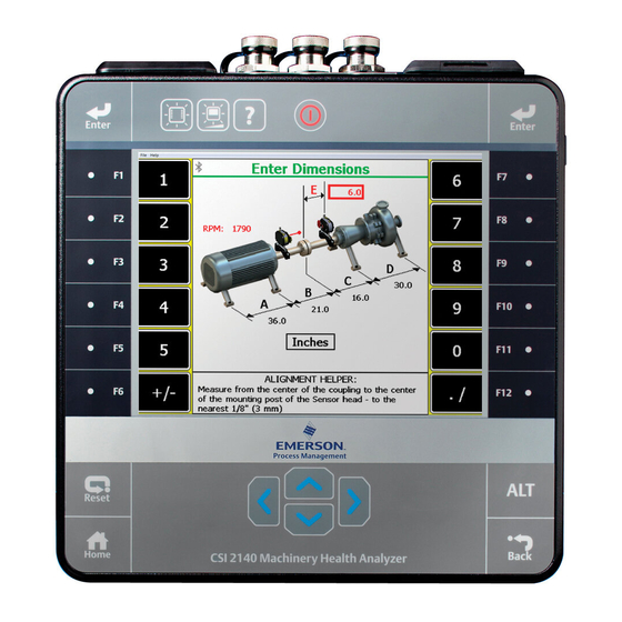
Enter dimensions Prerequisites 1. Ensure the laser and sensor are mounted on the machines. 2. Create and/or activate an alignment job and set up the job parameters. An alignment job is needed to perform alignment. AMS 2140 Advanced Laser Alignment Application... - Page 23 All machine dimensions must be entered before advancing to the thermal growth screens. 4. Enter thermal growth values if thermal growth is enabled and press Enter. Refer to the Alignment chapter of the AMS 2140 Machinery Health Analyzer User Guide for more information on entering thermal growth values.
- Page 24 2. If you enabled foot pre-check, then the foot pre-check screen launches automatically. Otherwise, press F12 Foot Pre-Check to start checking for soft foot. Refer to the Alignment chapter of the AMS 2140 Machinery Health Analyzer User Guide for more information on entering soft foot information.
- Page 25 December 2018 Quick Start Guide Auto Sweep Figure 4-2: Auto Sweep a. Position the laser and sensor at a starting angle (any angle). Make sure the laser and sensor are within 2° of each other. The position of the laser fixtures is marked on the screen with a black line on the green circle.
- Page 26 (0°, 90°, 180°, and 270°). Press F3 Accept Readings after stopping at each point. Note While it is always desirable to measure at all four cardinal positions, it is possible to estimate an alignment solution with only three measurements. AMS 2140 Advanced Laser Alignment Application...
- Page 27 December 2018 Quick Start Guide The status LED on the AMS 2140 flashes and an audible tone is produced whenever a reading is taken. The audible tone is only available when the Status Beeper is enabled (Home > ALT > F2 General Setup >...
- Page 28 If the required movement is negative, the amount of movement is shown below the machine at the appropriate foot with a down arrow. AMS 2140 Advanced Laser Alignment Application...
- Page 29 The bottom half of the AMS 2140 screen shows a bull’s-eye target and a shaft centerline plot representing the alignment condition of the machine. The shaft centerline plot includes a “V” shape indicating the acceptable angular tolerance on the machine as well as a bracket at the base of the “V”...
- Page 30 Quick Start Guide December 2018 Refer to the Alignment chapter of the AMS 2140 Machinery Health Analyzer User Guide for more information on calculating extra machine feet. b. Press F5 Alternate Move to switch between the alternate pairs of feet where the machine moves can be made.
- Page 31 The bottom half of the AMS 2140 screen shows a bull’s-eye target and a shaft centerline plot representing the alignment condition of the machine. The shaft centerline plot includes a “V” shape indicating the acceptable angular tolerance on the machine as well as a bracket at the base of the “V”...
- Page 32 As the machine is moved, the bottom half of the AMS 2140 screen provides a continuous update of the machine alignment condition. When the live move alert is enabled, the status LED on the AMS 2140 flashes and an audible alert is heard (only when the Status Beeper is set to on) when the target tolerance value is reached during a live move.
-
Page 33: Transfer Alignment Job Data And Tolerances
Transfer alignment job data and tolerances Transfer an alignment job to AMS Machinery Manager Prerequisites 1. Connect the AMS 2140 to a PC with AMS Machinery Manager installed and running. 2. Set the connection type on the AMS 2140. 3. Enable the AMS 2140 in Data Transfer. - Page 34 4. Set the connection type in Data Transfer. The connection type on the AMS 2140 and on Data Transfer must match. Refer to the AMS 2140 Machinery Health Analyzer User Guide for more information on setting the connection type on the AMS 2140 and on AMS Machinery Manager Data Transfer. Procedure 1.
- Page 35 December 2018 Quick Start Guide Refer to the AMS 2140 Machinery Health Analyzer User Guide for more information on setting the connection type on the AMS 2140 and on AMS Machinery Manager Data Transfer. Procedure 1. From the Laser Align Application main menu, press ALT > F9 Job Manager >...
-
Page 36: Print Alignment Summary Reports
You can save a report to a memory card if you inserted a card into the AMS 2140. Prerequisites On the AMS 2140, press Home > ALT > F2 General Setup > F6 Set Print Mode and ensure the default print mode is set to Store as BMP on CARD or Store as JPG on CARD. - Page 37 December 2018 Quick Start Guide 2. Enter up to 8 characters for a file name and press Enter. The AMS 2140 creates and saves the file to the memory card. The progress is displayed on the screen. Quick Start Guide...
-
Page 38: Verify The Ams Machinery Manager Version
Quick Start Guide December 2018 Verify the AMS Machinery Manager version The AMS 2140 Laser Align Application is compatible with AMS Machinery Manager v5.61 or later. AMS Machinery Manager 5.61 may require a patch to enable full functionality. If you are using AMS Machinery Manager v5.61, perform the following steps to verify that the patch is installed on your PC. -
Page 39: Sensalign Approvals
South Korea MSIP-CRM-PRc-sensALIGNsens TRA REGISTERED No: ER39483/15, DEALER No: DA43636/15 FCC: QOQWT41 Note The table above does not include all countries for which certificates have been issued. For a complete list, please contact your local Emerson Sales Representative. Quick Start Guide... - Page 40 All rights reserved. The Emerson logo is a trademark and service mark of Emerson Electric Co. All other marks are property of their respective...
Need help?
Do you have a question about the AMS 2140 and is the answer not in the manual?
Questions and answers