Advertisement
Available languages
Available languages
Quick Links
Installation and Maintenance Instructions
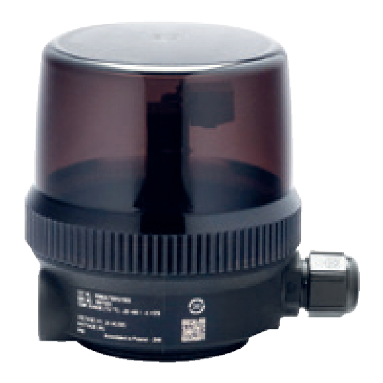
Signaling box ASCO™ series 890
DESCRIPTION
Asco pressure operated valves normally close (NC) and normally
open (NO) type can be equipped with a signaling box enabling
electrical monitoring of the 2 valve stem positions. This box,
consisting of a plastic enclosure, is available with mechanical or
inductive switches. In both valve stem positions (open or closed),
the end of the stem actuates the sensors, thus supplying an elec-
trical end-of-travel signal.
The signaling box exists with LED status indication for visu-
alization of valve position. It exists with an integrated pilot for
operating the valve. It exists with AS interface communication
protocol (AS-i).
Intended use
The signaling box is intended to be used with Asco 290 and 390
Series pressure operated valve for the purpose of being used
in general industries.
Essential Health and Safety Requirements:
The signaling box complies with the EMC Directive 2014/30/EU.
Working condition
Make sure operating conditions are below the most stringent
characteristics given on both the signaling box label and on the
valve label and follow additional specification below.
Additional Specifications:
Depending on configuration, characteristics are the following:
Supply voltage & Max power consumption
Per label characteristics.
Supply voltage ±10% with max. ripple 10%.
Breaking capacity of switches
• Mechanical microswitches:
0.5 A nominal / 1 A maximum / 24 V AC/DC
• Inductive switches: 100 mA / 24V DC
Ingress Protection level of apparatus:
IP66 according to IEC 60529.
IP69K according to ISO 20653.
Pilot & Air quality:
3/2 normally close type. When the pilot is
energized, valve actuator is operated. When the pilot is depres-
surized or deenergized, the valve moves to its rest position.
• Series 302 pilot, air filtered at 50 µm, lubricated or not, con-
densate-free and water-free.
• Series 518 pilot, air filtered at 25 µm, non-lubricated, conden-
sate-free and water-free.
Consult catalog pages for response time of signaling box and
valve assembly.
Electrical connection
Terminal strip grip: 2.5 mm². The terminal strip is of the plugging
type to facilitate connection.
• Cable gland: cable 4 mm to 8 mm dia.
• M12 Code B per IEC 61076-2-101 for version with commu-
nication.
AS-i communication version:
Device is supplied from the flat cable bus connection. No addi-
tional power cable needed.
Bus connection with M12 male connector per wiring diagram
given in the instruction manual (see page 33). Use pin number
references.
Communication protocol AS-Interface V2.1 extended addressing.
Profile per IEC 62026-2: S-7-A-E
Extended ID code 1 = 0
Visit our website at Emerson.com/ASCO
AS-i bit setting:
Function inductive
Function mechanical
Type
switches
switches
Type
OUTPUT
INPUT
INPUT
Pilot status
Valve close position
Valve open position
Bit = 1 = energized
Bit = 1 = activated
Bit = 1 = activated
D0
Bit = 0 = de-energized
Green light
Yellow light
Valve open position
Valve close position
-
Bit = 1 = activated
Bit = 1 = activated
D1
Yellow light
Green light
D2
-
D3
LED Status indication
( XXV, page 36)
• LED yellow = valve open position (1)
• LED green = valve close position (2)
• LED red = AS-i bus error (3)
• LED green = AS-i Power on (4) (visible only when cover is open).
Vibration
Max 1g /10-150Hz in 3 axes per EN 60068-2-6
STORAGE
The device must be kept in its original packaging as long as
it is left unused. Do not remove the protective covers from the
ports. Storage conditions: protected from exposure to weather;
storage temperature: -40°C to +70°C ; relative humidity: 95 %
After storage at low temperature, the device must gradually
be brought to room temperature prior to use.
INSTALLATION AND MAINTENANCE
The signaling box is supplied installed on valve and adjusted.
For installation and maintenance refer to the general safety
instructions.
Before any maintenance or installation operation, cut off the
electrical supply to the apparatus and check that the valve is
depressurized and drained. For work on the valve itself, refer
to the corresponding installation and maintenance instructions.
Warning:
Be careful of finger pinching risks when operating the valve with
the cover open for mechanical setting. Cut piloting pressure once
setting operation is done.
Be careful of electrical hazard when energizing the switches
or pilot for setting while cover is open.
Caution:
Be careful of risk of damage of mechanical switches when setting
cams or inserting the stem into the signaling box. Press manually
on the roller if needed ( V).
In case of harsh environment with dust and or water projection,
exhaust ports of signaling box and valve shall be ducted.
During the kit disassembly and reassembly, the screw must
be disengaged ( IV).
To avoid damage due to dirt or humidity penetration ensure
that the cable gland and the cover are tighten with all the
seals in place. The device must be operated only with its cover
closed ( XX).
Note:
• Fast assembly ( VII) is possible with valves normally
closed (NC) equipped with plastic (63 mm to 125 mm dia.)
or stainless steel (63 mm to 90 mm dia.) actuators.
• Screwed assembly ( VIII) is possible with:
- valves normally open (NO) with plastic or stainless steel
versions;
- valves normally closed (NC) with 50 mm plastic actuator.
Installation (see pages 30 and 31)
1. Remove the indicator cap (A) ( I). Do not remove the
o-ring (B) if present.
2
Installation and Maintenance Instructions
EN
2. Unscrew and remove the optical indicator (C) ( II)
For NC valve air must be supplied to the actuator in order
to unscrew the optical indicator.
3. Remove the cover (D) by un-screwing by hand ( III).
4. Separate the assembly kit from the signaling box: ( IV-V-VI)
5. For the fast assembly ( VII) introduce the assembly kit and
screw the adaptor (E) on the valve. Tighten to the torque
indicated.
6. For the screwed assembly kit ( VIII):
- Put threadlocker (Loctite
®
222) (F) in the tapping.
- Screw by hand the stem (G) on the rod of the valve until
contact.
- Screw the adaptor (E). Tighten to the torque indicated.
7. Insert the signaling box (H) and tighten the screw (J) ( XI).
Electrical Connection (see page 32 and 33)
All power cables must have a sufficient cross-section and a suf-
ficient insulation. They must be installed in a compliant manner.
1. Loosen the cable gland (K) ( XX);
2. Introduce the electrical cable through the gland (L) ( XX);
3. Connect the cable according to your configuration:
Use terminal block (M) for the open & close position signals;
Use terminal block (P) to connect pilot.
- For mechanical switches without LED
and without pilot ( XXI);
- For inductive switches ( XXII);
- For mechanical switches with LED ( XXIII).
4. Tighten the cable gland (K) ( XX).
AS-i version
Connect M12 female cable (Q) ( XXIV).
Pneumatic Connection (see page 34)
This applies to product with internal pilot. The signaling box is sup-
plied with pneumatic accessories to connect to valve. Fittings
and tubes can be replaced by user for its specific application.
1. For NC version assemble the flexible tube (R) on the connec-
tion (S) ( XXX). Tighten to the specified torque.
2. For NO Version assemble the flexible tube (R) on the connec-
tion (T) ( XXXI). Tighten to the specified torque.
Cams adjustment (see pages 35 and 36)
Note: If the screws (U) & (V) are not visible, orient the body
of signaling box (X) as needed by unscrewing the set screw (Y)
and then by tightening it to required torque or rotate stem
as needed ( XXXV).
- Adjust the cam ( XXXV).
- Adjust the cam through by the oblong hole for version with
pilot ( XXXVI).
Warning: Be careful of finger punching risks.
For mechanical switches version:
1. Cams adjusting for NC version:
- Set cam (Z) until position detection that correspond to close
position. Use the screw (V) ( XXXVII). During the adjust-
ment of the cam press manually on the roller (AA) if needed.
- Before adjusting these second cam,position it against the
first to avoid damage to mechanical switch.
- Operate the valve to open position.
- Set cam (AB) until position detection that correspond to open
position. Use the screw (U) ( XXXVIII).
During the adjustment of the cam press manually on the
roller (AC) if needed.
2. NO version:
- Set cam (AB) until position detection that correspond to open
position. Use the screw (U) ( XXXIX). During the adjust-
ment of the cam press manually on the roller (AC) if needed.
- Before adjusting these second cam, position it against the
first to avoid damage to mechanical switch.
- Operate the valve to close position.
- Set cam (Z) until position detection that correspond to close
position. Use the screw (V) ( XXXX).
During the adjustment of the cam press manually on the
roller (AA) if needed.
For inductive switches version
1. Energize the switches.
2. NC version ( XXXXI):
- Set cam (Z) until position detection that correspond to close
position. Use the screw (V).
Signaling box ASCO™ series 890
- Operate the valve to open position.
- Set cam (AB) until position detection that correspond to open
position. Use the screw (U).
3. NO version ( XXXXI):
- Set cam (AB) until position detection that correspond to open
position. Use the screw (U).
- Operate the valve to close position.
- Set cam (Z) until position detection that correspond to close
position. Use the screw (V).
4. Denergized the switches and the pilot.
Check electrical signals.
Close the cover (D) with the appropriate gasket and tighten
it by hand until complete contact between the cover and the
body ( XXXXII).
Preventive maintenance
Visually inspect the box once a month. Check: that there are
no foreign objects inside the box and that there is no moisture
inside, that the box is correctly secured against rotation.
Malfunctioning
In the event of failure to detect the open or closed position:
- if, during an operating cycle, the stem does not move or moves
abnormally: Check the pressures (valve and pilot), the operation
of the valve and the control system
- if the stem is correctly activated: Check the electrical supply
to the switches, the adjustment of the cams at opening and
closing positions, the state of the switches, the state of the
printed circuit board.
If the defect has not been rectified nor identified contact the
After Sales Service.
E S D
CAUTION
OBSERVE
PRECAUTIONS
FOR HANDLING
ELECTROSTATIC
SENSITIVE
DEVICES
(
XXXXI):
3
Visit our website at Emerson.com/ASCO
EN
This product contains electronic compo-
nents sensitive to electrostatic discharge.
An electrostatic discharge generated
by a person or object coming in contact
with the electrical components can dam-
age or destroy the product. To avoid the
risk of electrostatic discharge, please
observe the handling precautions and
recommendations contained in standard
EN 100015-1.
Do not connect or disconnect the
device while it is energised.
Advertisement

Related Manuals for Emerson Asco 890 Series


Summary of Contents for Emerson Asco 890 Series
- Page 1 - Set cam (Z) until position detection that correspond to close Installation (see pages 30 and 31) position. Use the screw (V). 1. Remove the indicator cap (A) ( I). Do not remove the o-ring (B) if present. Visit our website at Emerson.com/ASCO Visit our website at Emerson.com/ASCO...
- Page 2 - Avant de régler cette deuxième came, positionnez-la contre normalement fermée (NF) équipées d'actionneurs en plastique la première pour éviter d'endommager le capteur mécanique. (Ø63 mm à Ø125 mm) ou acier inox (Ø63 mm à Ø90 mm). Visit our website at Emerson.com/ASCO Visit our website at Emerson.com/ASCO...
-
Page 3: Installation Und Wartung
(NC) Ventilen mit Kunststoffstellgliedern (63 mm bis 125 mm Durchm.) oder Edelstahlstellgliedern (63 mm bis Bei der Einstellung des Nockens bei Bedarf manuell auf die 90 mm Durchm.) möglich. Rolle (AC) drücken. Visit our website at Emerson.com/ASCO Visit our website at Emerson.com/ASCO... - Page 4 (63 mm a 125 mm de diámetro) o de acero inoxidable (63 mm Código ID extendido 1 = 0 a 90 mm de diámetro). mente sobre el rodillo (AC) si es necesario. Visit our website at Emerson.com/ASCO Visit our website at Emerson.com/ASCO...
- Page 5 Il dispositivo deve essere azionato solo che corrisponde alla posizione aperta. Usare la vite (U) con il suo coperchio chiuso ( XX). ( XXXVIII). Durante la regolazione della camma premere manualmente Visit our website at Emerson.com/ASCO Visit our website at Emerson.com/ASCO...
-
Page 6: Installatie En Onderhoud
(63 mm tot 125 mm dia.) eenkomt met de geopende stand. Gebruik de schroef (U) of roestvrijstalen (63 mm tot 90 mm dia.) actuators. ( XXXVIII). Visit our website at Emerson.com/ASCO Visit our website at Emerson.com/ASCO... - Page 7 Bruk skrue (V) ( XXXX). rustfritt stål; Ved justering av kammen, trykk manuelt på rullen (AA) hvis det er nødvendig. - ventiler som normalt er lukket (NC) med 50 mm aktuator i plast. Visit our website at Emerson.com/ASCO Visit our website at Emerson.com/ASCO...
- Page 8 Använd skruven (V) ( XXXX). - ventiler normalt slutna (NC) med 50 mm ställdon av plast. Vid justering av kammen, tryck manuellt på rullen (AA) vid behov. Visit our website at Emerson.com/ASCO Visit our website at Emerson.com/ASCO...
- Page 9 Nokan säätämisen aikana voit tarvittaessa painaa rullaa malleissa: (AA) käsin. - normaalisti avoimet (NO) venttiilit muoviversiolla tai ruostu- mattomalla teräsversiolla - normaalisti suljetut (NC) venttiilit 50 mm:n muovisella toimi- laitteella. Visit our website at Emerson.com/ASCO Visit our website at Emerson.com/ASCO...
- Page 10 Brug skruen (V) ( XXXX). Under justering af knasten skal du trykke manuelt på rullen - normalt lukket-ventiler (NC) med 50 mm plast-aktuator. (AA) efter behov. Visit our website at Emerson.com/ASCO Visit our website at Emerson.com/ASCO...
-
Page 11: Instalação E Manutenção
( XX). ponde à posição aberta. Utilizar o parafuso (U) ( XXXVIII). Durante o ajuste do excêntrico, carregar manualmente no rolo (AC), se necessário. Visit our website at Emerson.com/ASCO Visit our website at Emerson.com/ASCO... - Page 12 και ελέγξτε ότι όλες οι τσιμούχες είναι στη θέση τους. Η συσκευή θα ναντι από το πρώτο για να μην προκληθεί ζημιά στον μηχανικό πρέπει να τίθεται σε λειτουργία μόνο με το κάλυμμα κλειστό ( XX). διακόπτη. Visit our website at Emerson.com/ASCO Visit our website at Emerson.com/ASCO...
- Page 13 Během seřizování vačky v případě potřeby ručně zatlačte - ventily typu normálně otevřené (NO) v plastovém nebo nere- na váleček (AA). zovém provedení; - ventily typu normálně zavřené (NC) s 50 mm plastovým pohonem. Visit our website at Emerson.com/ASCO Visit our website at Emerson.com/ASCO...
- Page 14 TROSTATYCZNE kami na miejscu. Urządzenie może być obsługiwane wyłącznie nika mechanicznego. z zamkniętą pokrywą ( XX). - Ustawić zawór w pozycji otwartej. Visit our website at Emerson.com/ASCO Visit our website at Emerson.com/ASCO...
- Page 15 8 ±1 30 mm 6 mm & 3 mm 6 mm 2 mm & Visit our website at Emerson.com/ASCO & Visit our website at Emerson.com/ASCO Visit our website at Emerson.com/ASCO...
- Page 16 Closed valve signal name M12 male ASI + Pin 1 Pin 2 Pin 3 ASI - Pin 4 Pin 5 Open Open Close Visit our website at Emerson.com/ASCO Close Visit our website at Emerson.com/ASCO posi on posi on posi on posi on...
- Page 17 1/4" XXXI Exhaust connec on Pilo ng connec on Supply connec on XXXIX XXXX 1.5 mm 1.5 mm CF 3M Inch.Pounds 14409 0.6 ±0.1 5 ±0.9 Visit our website at Emerson.com/ASCO Visit our website at Emerson.com/ASCO...
- Page 18 Justering av kammer Regulacja krzywek XXXXI 1.5 mm 1.5 mm XXXXII Emerson Automation Fluid Control & Pneumatics Poland Sp. z o. o. ul. Kurczaki 132 Visit our website at Emerson.com/ASCO 93-331 Lodz POLAND Visit our website at Emerson.com/ASCO...
- Page 19 Installation (see pages 12 to 13) position. Use the screw (V). 1. Remove the indicator cap (A) ( I). Do not remove the - Operate the valve to open position. o-ring (B) if present. Visit our website at Emerson.com/ASCO Visit our website at Emerson.com/ASCO...
- Page 20 - Állítsa a bütyköt (AB) a helyzetérzékelőhöz, mely megfelel között.) működtetők. a nyitott helyzetnek. Használja a csavart (U) ( XXXIX). A bütyök beállítása közben nyomja meg kézzel a görgőt (AC), ha szükséges. Visit our website at Emerson.com/ASCO Visit our website at Emerson.com/ASCO...
- Page 21 Профиль согласно IEC 62026-2: S-7-A-E уплотнениями. Устройство должно эксплуатироваться только нического переключателя. РАЗРЯДАМ Расширенный идентификационный код 1 = 0 с закрытой крышкой ( XX). - Переведите клапан в открытое положение. Visit our website at Emerson.com/ASCO Visit our website at Emerson.com/ASCO...
- Page 22 Ескертпе: - Ашық күйге сәйкес күй анықталғанша, жұдырықшаны (AB) • Пластикалық (диаметрі 63-125 мм) немесе тот баспайтын орнатыңыз. Бұранданы (U) пайдаланыңыз ( XXXVIII). болат (диаметрі 63-90 мм) жетектерімен жабдықталған Visit our website at Emerson.com/ASCO Visit our website at Emerson.com/ASCO...
- Page 23 至 90 mm)执行器的常闭 (NC) 阀门可实现快速装配 ( VII)。 - 设置凸轮 (AB),直到检测到与打开位置相对应的位置。使用 • 螺纹装配 ( VIII) 适用于以下情况: 螺钉 (U) ( XXXIX)。在调整凸轮期间,如果需要,应手动 - 塑料或不锈钢版本的常开 (NO) 阀门; 按压滚轮 (AC)。 - 带 50 mm 塑料执行器的常闭 (NC) 阀门。 Visit our website at Emerson.com/ASCO Visit our website at Emerson.com/ASCO...
- Page 24 网站:www.emerson.com 30 mm 6 mm & 3 mm 6 mm 2 mm & Visit our website at Emerson.com/ASCO & Visit our website at Emerson.com/ASCO Visit our website at Emerson.com/ASCO...
- Page 25 Power (+24V) Power (+24V) +24V Closed valve signal Closed valve signal ASI + Pin 1 Pin 2 Pin 3 ASI - Pin 4 Pin 5 Visit our website at Emerson.com/ASCO Visit our website at Emerson.com/ASCO Close Open posi on posi on...
- Page 26 XXXIX XXXX 1.5 mm 1.5 mm Inch.Pounds CF 3M 14409 0.6 ±0.1 5 ±0.9 世格流体控制(上海)有限公司 世格流体控制(上海)有限公司 Visit our website at Emerson.com/ASCO Visit our website at Emerson.com/ASCO 中国•上海市松江区新桥镇新庙三路 480 号 邮编:201612 中国•上海市松江区新桥镇新庙三路 480 号 邮编:201612 电话:(86-21)57071888 客户服务热线:800-820-2323 电话:(86-21)57071888 客户服务热线:800-820-2323 网站:www.emerson.com...
- Page 27 Bütykök beállítása Жұдырықшаларды реттеу 凸轮调整 XXXXI 1.5 mm 1.5 mm XXXXII Emerson Automation Fluid Control & Pneumatics Poland Sp. z o. o. Visit our website at Emerson.com/ASCO ul. Kurczaki 132 Visit our website at Emerson.com/ASCO 93-331 Lodz POLAND...
Need help?
Do you have a question about the Asco 890 Series and is the answer not in the manual?
Questions and answers