
Subscribe to Our Youtube Channel
Related Manuals for Emerson Rosemount 9195


Summary of Contents for Emerson Rosemount 9195
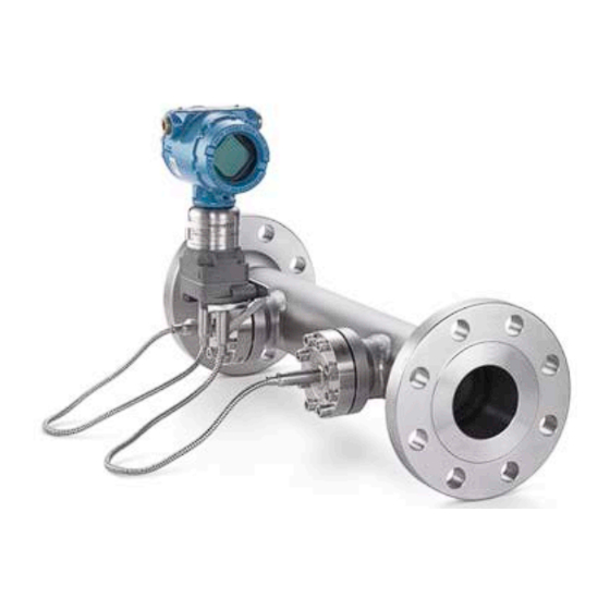
- Page 1 Quick Start Guide 00825-0100-4488, Rev AA November 2023 Rosemount 9195 Wedge Meter ™ Assembly...
- Page 2 Manual. The manual and this guide are also available electronically on Emerson.com/ Rosemount. If the Rosemount 9195 Primary Element was ordered assembled to a Rosemount Pressure Transmitter or a Rosemount 1199 Diaphragm Seal System, refer to the following Quick Start Guides for information on configuration and hazardous locations certifications: •...
-
Page 3: Table Of Contents
November 2023 Quick Start Guide WARNING Physical access Unauthorized personnel may potentially cause significant damage to and/or misconfiguration of end users’ equipment. This could be intentional or unintentional and needs to be protected against. Physical security is an important part of any security program and fundamental to protecting your system. - Page 4 Quick Start Guide November 2023 Emerson.com/Rosemount...
-
Page 5: Before You Begin
1 Before you begin Before you begin the installation, consider the vibration and temperature limits of the meter. Refer to the Rosemount 9195 Wedge Meter Product Data Sheet, flow sizing, or instrument tag for functional limits. Figure 1-1: Exploded View 1: Compact Remote Seal (WSP Style) A. - Page 6 If using primary isolation valves (option codes BV1 and GV1 in the model number), valves and valve gaskets are installed between the branch gasket (L) and the flushing ring or remote seal (K or J). Ensure a gasket is used between all connection points. Emerson.com/Rosemount...
- Page 7 November 2023 Quick Start Guide Figure 1-3: Exploded View 3: ½-inch NPT Tubed Assembly A. Wedge Primary Element Meter Body B. Manifold C. Transmitter D. Mounting Lock Washers E. Mounting Screws F. Formed Tubing G. Compression Fittings Quick Start Guide...
-
Page 8: Locate The Installation Point
Downstream (outlet) side of primary (all disturbances) Consult an Emerson representative if a disturbance is not listed. Upstream straight pipe run diameters are measured from the upstream pressure taps of the Rosemount 9195 primary element. Downstream straight pipe run diameters are measured from the downstream pressure taps. - Page 9 3. Remove the manifold from the mounting bracket. 4. Remove the transmitter from the manifold. 5. Rotate the transmitter 180º on the manifold, ensuring the high and low pressure ports match those on the Rosemount 9195 meter body. Tighten the bolts as shown in Table 2-2.
- Page 10 10. Verify the flange bolts are protruding through the sensor module before applying pressure. Table 2-2: Torque Values for Transmitter Mounting Bolts Bolt material Head Initial torque Final torque markings Carbon steel 300 in-lb 650 in-lb (CS) Stainless steel 150 in-lb 300 in-lb (SST) Emerson.com/Rosemount...
-
Page 11: Orient The Primary Element
November 2023 Quick Start Guide 3 Orient the primary element The primary element should be installed as recommended below. Manifold or flushing ring vents should be positioned to allow for bleeding or venting. Orienting the unit within the recommended zone will also prevent inaccurate measurements. Determine the orientation based on the application type, mounting type, flow direction, and the flow meter’s orientation in relation to the pipe. - Page 12 Based on Gas, Liquid, or Steam Fluid Types Note Vertical flow will add additional uncertainty. Refer to the Rosemount 9195 Reference Manual for more information. Note Steam and liquid flowing vertically down can be associated with increased signal noise and are generally not recommended.
- Page 13 November 2023 Quick Start Guide 3.2 Integrated meter orientations for tubed assemblies Figure 3-3: Horizontal Flow for Direct Mount Orientations Based on a Liquid or Steam Fluid Type Quick Start Guide...
- Page 14 Quick Start Guide November 2023 Figure 3-4: Horizontal Flow for Direct Mount Orientations Based on a Gas Fluid Type Emerson.com/Rosemount...
- Page 15 November 2023 Quick Start Guide Figure 3-5: Vertical Flow for Direct Mount Orientations Based on a Dry Gas Fluid Type Quick Start Guide...
- Page 16 Quick Start Guide November 2023 Figure 3-6: Horizontal Flow for Remote Mount Orientations Based on a Liquid or Steam Fluid Type Note Root valves shown in the image are not provided with the 9195 Wedge primary element. Emerson.com/Rosemount...
- Page 17 November 2023 Quick Start Guide Figure 3-7: Horizontal Flow for Remote Mount Orientations Based on a Gas Fluid Type Quick Start Guide...
- Page 18 Quick Start Guide November 2023 Figure 3-8: Vertical Flow for Remote Mount Orientations Based on a Liquid or Steam Fluid Type Emerson.com/Rosemount...
- Page 19 Figure 3-9: Vertical Flow for Remote Mount Orientations Based on a Gas Fluid Type Note Vertical flow will add additional uncertainty. Refer to the Rosemount 9195 Reference Manual for more information. Note Not applicable for remote seal applications. Note For remote mount installations, use stainless steel tubing with the largest convenient internal diameter per site practices.
-
Page 20: Install The Primary Element
When connecting the upper and lower housing make sure the gasket is aligned properly on the gasket sealing surface. b) For flanged assemblies: when connecting the process and mating flange, the bolts should be torqued to the applicable flange requirements. Emerson.com/Rosemount... - Page 21 November 2023 Quick Start Guide c) For Compact Seal (WSP) assemblies: ensure that the remote seal screws and/or nuts are torqued to 180 in-lb (20 N-m). d) For general handling of the remote seal system: 1. When unpacking or handling seal system assemblies, do not lift the seal or transmitter by gripping the capillaries;...
- Page 22 6. Use the appropriate studs, nuts, gaskets, and torque specifications for the given flange size, rating, and process conditions. Tighten the nuts following a star or cross pattern. Emerson.com/Rosemount...
-
Page 23: Preparing For Operation
November 2023 Quick Start Guide 5 Preparing for operation WARNING Serious injury can occur by opening the valves when the pipe is pressurized. Do not bleed or vent process fluid if it is toxic or harmful to health or the environment. 5.1 ... - Page 24 5.3 Tubed remote mount Procedures for mounting based on fluid type. 5.3.1 Gas applications—transmitter located above Rosemount 9195 taps Procedure 1. Start the procedure by closing all the valves on the unit. 2. Open both transmitter manifold isolation valves. 3. Open the transmitter manifold vent valves slightly to allow for the removal of trapped liquids.
- Page 25 9. Open the transmitter manifold low side isolation. The system is now operational. 5.3.3 Steam applications-transmitter located below Rosemount 9195 taps for remote mount Procedure 1. Remove pressure from line and close all valves on the transmitter manifold. 2. Open both transmitter manifold isolation valves.
-
Page 26: Product Certifications
Rosemount, Inc.: Shakopee, Minnesota USA Rosemount DP Flow Design and Operations: Boulder, Colorado USA Emerson Process Management: Cluj-Napoca, Romania Emerson Asia Pacific Private Limited: Singapore Emerson Beijing Instrument Co., Ltd: Beijing, China Emerson's Solutions Center in Dubai, UAE 6.2 European Directive information... - Page 27 November 2023 Quick Start Guide Figure 6-1: Rosemount 9195 Declaration of Conformity EU Declaration of Conformity EMERSON. No: DSI 1000 Rev. Z Rosemount/ Dieterich Standard, Inc. 5601 North 71 Street Boulder CO 80301 declare under our sole responsibility that the products,...
- Page 28 CAT II* 9195, CL300/PN40 to CL600/PN100, NPS 3 (DN80) to NPS 4 (DN100) CAT II* CAT II 9195, CL300/PN40 to CL600/PN100, NPS 6 (DN150) to NPS 8 (DN200) CAT III CAT II Page 2 of 5 July 19, 2023 Emerson.com/Rosemount...
- Page 29 November 2023 Quick Start Guide EU Declaration of Conformity No: DSI 1000 Rev. Z Summary of Classifications – Group 1 Dangerous Fluids Hazard Classification Model/Range Liquid 9195, CL600/PN100, NPS 2 (DN50) CAT II* CAT II *When fluid is an unstable gas, these items are Cat III Page 3 of 5 July 19, 2023 Quick Start Guide...
- Page 30 9195, CL150/PN16, NPS 3 (DN80) to NPS 8 (DN200) CAT I 9195, CL300/PN40 to CL600/PN100, NPS 2 (DN50) to NPS 4 (DN100) CAT I 9195, CL300/PN40 to CL600/PN100, NPS 6 (DN150) to NPS 8 (DN200) CAT II Page 4 of 5 July 19, 2023 Emerson.com/Rosemount...
- Page 31 November 2023 Quick Start Guide EU Declaration of Conformity No: DSI 1000 Rev. Z RoHS Directive (2011/65/EU) Models 3051CFx, 2051CFx Harmonized standard: EN 50581:2012 Only applies to the following models: 3051CFx with 4-20 mA HART output code A 3051CFx with FOUNDATION Fieldbus output code F 3051CFx with Profibus PA output code W 2051CFx with 4-20 mA HART output code A Page 5 of 5...
- Page 32 2023 Emerson. All rights reserved. Emerson Terms and Conditions of Sale are available upon request. The Emerson logo is a trademark and service mark of Emerson Electric Co. Rosemount is a mark of one of the Emerson family of companies. All other marks are the property of their respective owners.
Need help?
Do you have a question about the Rosemount 9195 and is the answer not in the manual?
Questions and answers