Table of Contents
Advertisement
Quick Links
Advertisement
Table of Contents

Related Manuals for Pentair FLECK 5810 SXT


Summary of Contents for Pentair FLECK 5810 SXT
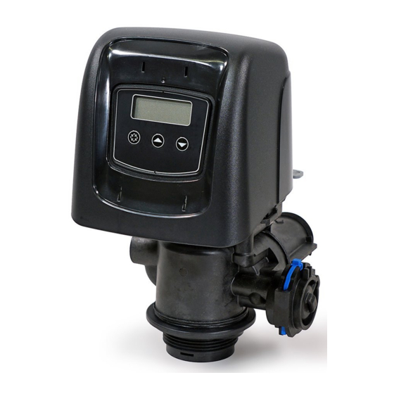
- Page 1 FLECK 5810 SXT INSTALLER MANUAL WATER PURIFICATION...
-
Page 2: Table Of Contents
Installer Manual Fleck 5810 - SXT - Table of contents Table of contents Generalities ......... . 7 1.1. - Page 3 Installer Manual Fleck 5810 - SXT - Table of contents System sizing ........28 4.1.
- Page 4 Installer Manual Fleck 5810 - SXT - Table of contents Programming ........52 6.1.
- Page 5 Installer Manual Fleck 5810 - SXT - Table of contents Commissioning ........74 7.1.
- Page 6 Installer Manual Fleck 5810 - SXT - Table of contents Troubleshooting ........94 10.1.
-
Page 7: Generalities
Part numbers actualisation. Address change, Bleam information and valve on 08.06.2018 BRY/FIM tank assembly. 1.3. Manufacturer identifier, product Manufacturer: Pentair International LLC Avenue de Sevelin 18 1004 Lausanne Switzerland Product: Fleck 5810 - SXT 1.4. Intended use The device is intended to be used for residential, commercial and light industrial applications only and it is purpose-built for water treatment. -
Page 8: Abbreviations Used
Installer Manual Fleck 5810 - SXT - Generalities 1.5. Abbreviations used BLFC ............Brine Line Flow Controller BV ............Brine Valve DF............Down Flow DLFC ............Drain Line Flow Controller Inj ............Injector QC............Quick Connect Regen ............Regeneration S&S ............Seals & Spacers SBV............ -
Page 9: Procedure For Technical Support
Pentair Quality System EMEA products benefit, under specific conditions, from a manufacturer warranty that may be invoked by Pentair’s direct customers. Users should contact the vendor of this product for applicable conditions and in case of a potential warranty claim. -
Page 10: Scan & Service Application
Installer Manual Fleck 5810 - SXT - Generalities 1.10. Scan & Service application Scan & Service mobile application is the ideal support for the maintenance person in his daily business. A simple scan of an identification (ID) label (1) present on the valve with a smartphone gives an instantaneously access to all updated information related to the product, such as: •... -
Page 11: Safety
Installer Manual Fleck 5810 - SXT - Safety Safety 2.1. Safety pictograms definition Caution Warning Warns of a risk of minor injury or major Warns against serious personal injury material damage to the device or and damage to health. environment. Danger... -
Page 12: Hazards
Installer Manual Fleck 5810 - SXT - Safety 2.3. Hazards All the safety and protection instructions contained in this document must be observed in order to avoid temporary or permanent injury, damage to property or environmental pollution. At the same time, any other legal regulations, accident prevention and environmental protection measures, as well as any recognized technical regulations relating to appropriate and risk-free methods of working which apply in the country and place of use of the device must be adhered to. -
Page 13: Hygiene Measures
Installer Manual Fleck 5810 - SXT - Safety Assembly • Assemble only with components which are in accordance with drinking water standards; • after installation and before use, perform one or more manual regenerations in order to clean the media bed. During such operations, do not use the water for human consumption. Perform a disinfection of the system in the case of installations for treatment of drinking water for human use. -
Page 14: Description
Installer Manual Fleck 5810 - SXT - Description Description 3.1. Technical specifications Design specifications/ratings Valve body ..........Fiber-reinforced polymer Rubber components ....... EP/EPDM Valve material certification ....DM174, ACS, CE Weight (valve with controller) ....2.3 kg (max) Recommended operating pressure ..1.4 - 8.6 bar Maximum inlet pressure ...... -
Page 15: Performance Flow Rate Characteristics
Installer Manual Fleck 5810 - SXT - Description Environmental conditions • Indoor use only; • temperature from 0°C to 52°C; • maximum relative humidity 80% for temperatures up to 31°C decreasing linearly to 50% relative humidity at 40°C; • mains supply voltage fluctuations up to ±10% of the nominal voltage. 3.1.1. -
Page 16: Outline Drawing
Installer Manual Fleck 5810 - SXT - Description 3.2. Outline drawing 16 / 106 Ref. MKT-IM-016 / C - 08.06.2018... -
Page 17: Description And Components Location
Installer Manual Fleck 5810 - SXT - Description 3.3. Description and components location Controller LCD screen Regen button Up button Brine line Down button Injector block Drain line Mixing device Inlet Outlet Piston Brine valve Meter* *Not included in case of timeclock Ref. -
Page 18: System Regeneration Cycle
Installer Manual Fleck 5810 - SXT - Description 3.4. System regeneration cycle Note This valve allows to do down flow or up flow regenerations. 3.4.1. Downflow regeneration cycle (5-cycles operation) Service — normal use Untreated water is directed down through the resin bed and up through the riser tube. The hardness ions attach themselves to the resin and are removed from the raw water being exchanged on the resin beads against sodium ions. - Page 19 Installer Manual Fleck 5810 - SXT - Description Note For illustration purpose only. Always verify inlet and outlet marking on the valve. SERVICE NORMAL USE BACKWASH Outlet Inlet Outlet Inlet Drain Valve Valve BRINE DRAW & SLOW RINSE RAPID RINSE Outlet Inlet Outlet...
-
Page 20: Upflow Regeneration Cycle (5-Cycles Operation)
Installer Manual Fleck 5810 - SXT - Description 3.4.2. Upflow regeneration cycle (5-cycles operation) Service — normal use Untreated water is directed down through the resin bed and up through the riser tube. The hardness ions attach themselves to the resin and are removed from the raw water being exchanged on the resin beads against sodium ions. - Page 21 Installer Manual Fleck 5810 - SXT - Description Note For illustration purpose only. Always check for inlet and outlet marking on the valve. SERVICE NORMAL USE BRINE DRAW & SLOW RINSE Outlet Inlet Outlet Inlet Drain Valve Valve From brine tank BACKWASH RAPID RINSE...
-
Page 22: Upflow Fill First Regeneration Cycle (5-Cycles Operation)
Installer Manual Fleck 5810 - SXT - Description 3.4.3. Upflow fill first regeneration cycle (5-cycles operation) Service — normal use Untreated water is directed down through the resin bed and up through the riser tube. The hardness ions attach themselves to the resin and are removed from the raw water being exchanged on the resin beads against sodium ions. - Page 23 Installer Manual Fleck 5810 - SXT - Description Note For illustration purpose only. Always check for inlet and outlet marking on the valve. SERVICE NORMAL USE BRINE REFIL Outlet Inlet Outlet Inlet Valve Valve To brine tank SERVICE BRINE DRAW & SLOW RINSE Outlet Inlet Outlet...
-
Page 24: Filter Cycle (3-Cycles Operation)
Installer Manual Fleck 5810 - SXT - Description 3.4.4. Filter cycle (3-cycles operation) Service — normal use Unfiltered water is directed down through the media and up through the riser tube. The water is filtered as it passes through the media. Backwash —... - Page 25 Installer Manual Fleck 5810 - SXT - Description Note For illustration purpose only. Always verify inlet and outlet marking on the valve. SERVICE NORMAL USE BACKWASH Outlet Inlet Outlet Inlet Drain Valve Valve SERVICE RAPID RINSE NORMAL USE Outlet Inlet Outlet Inlet Drain...
-
Page 26: Configurations For Downflow Softener, Upflow Softener And Filter
Installer Manual Fleck 5810 - SXT - Description 3.5. Configurations for downflow softener, upflow softener and filter 3.5.1. Downflow softener The valve is mounted with the DF piston kit, part number 61956-01. The injector is installed in the upper hole and the plug in the lower hole. 3.5.2. -
Page 27: Options Available On The Valve
Installer Manual Fleck 5810 - SXT - Description 3.6. Options available on the valve Mixing device The valve can be equipped with a mixing device (1) whose function is to regulate the hardness of the water at the outlet. The mixing can be set from 0% to 50% of hard water (i.e. 0 turn = 0% of hard water with 100% of treated water and 1-½... -
Page 28: System Sizing
Installer Manual Fleck 5810 - SXT - System sizing System sizing 4.1. Recommendations 4.1.1. Injector/DLFC/BLFC-Valve configuration Tank Resin Injector DLFC BLFC Valve diameter volume type [in] Color Color [gpm] DF [gpm] UF [gpm] 9 - 21 Violet Brown 22 - 28 Violet 0.25 0.25... - Page 29 Installer Manual Fleck 5810 - SXT - System sizing The below sizing method can be applied for both residential and industrial softeners. The sizing of a softener must be based upon certain parameters: • inlet water hardness; • peak flow rate and nominal flow rate; •...
-
Page 30: Determining The Required Volume Of Resin
Installer Manual Fleck 5810 - SXT - System sizing Piping size (internal diameter) Max. flow rate [in] [mm] /h at 3 m/s] 1.25 8.69 13.57 21.20 34.2 49.2 4.2.2. Determining the required volume of resin When sizing a softener, make sure that the volume of resin in the tank (bed volume) will be sufficient so that even when the peak flow rate is reached, the velocity is still between the above values depending on the hardness. -
Page 31: Resin Exchange Capacity And Capacity Of The Unit
Installer Manual Fleck 5810 - SXT - System sizing 4.2.3. Resin exchange capacity and capacity of the unit The resin exchange capacity and capacity of the unit are two different things that should not be confused. The resin exchange capacity is the amount of Ca and Mg that can be retained by 1 litre of resin, which will depend on the resin type and salt dosage, whereas the capacity of the unit is the... - Page 32 Installer Manual Fleck 5810 - SXT - System sizing Salt amount Corresponding resin exchange °f.m °dH.m [g/L capacity in [g/L ] as CaCO [per L [per L resin resin resin resin 58.5 5.85 3.27 62.7 6.27 66.9 6.69 3.74 3.97 75.3 7.53 4.21...
-
Page 33: Valve Configuration
Installer Manual Fleck 5810 - SXT - System sizing 4.2.4. Valve configuration Knowing the volume of resin, tank size and specifications of the resin, it is possible to determine the required valve configuration. The resin specification will give the backwash velocity, as well as the brine draw and slow rinse velocity that must be respected in order to ensure a proper regeneration of the unit. -
Page 34: Cycle Time Calculation
Installer Manual Fleck 5810 - SXT - System sizing 4.2.5. Cycle time calculation From this point, the volume of resin, the tank size, the capacity of the softener and the valve configuration are determined. Next step is to calculate the regeneration cycle duration, which depends on the valve configuration and once again on the resin specifications. - Page 35 Installer Manual Fleck 5810 - SXT - System sizing To calculate the brine draw duration: Knowing the injector draw flow rate at the working pressure: with: brine draw brine draw : brine draw duration [min] brine draw : brine volume to be drawn [L], see Refill calculation brine page 36 : injection draw flow rate [L/min]...
-
Page 36: Salt Amount Definition
Installer Manual Fleck 5810 - SXT - System sizing To calculate the refill duration: The refill flow rate is controlled by the refill controller (BLFC). The relation between the BLFC size, the tank size and the resin volume is given in the valve specifications. To calculate the refill duration: with: refill... -
Page 37: 1650 Injector Flow Rates
Installer Manual Fleck 5810 - SXT - System sizing 4.4. 1650 Injector flow rates The following tables and graphics represent the injectors flow rate as a function of the inlet pressure for the different injector sizes. INJECTOR 000 Total Rinse Draw Inlet pressure [bar] INJECTOR 00... - Page 38 Installer Manual Fleck 5810 - SXT - System sizing INJECTOR 0 Total Rinse Draw Inlet pressure [bar] INJECTOR 1 Total Rinse Draw Inlet pressure [bar] INJECTOR 2 Total Rinse Draw Inlet pressure [bar] 38 / 106 Ref. MKT-IM-016 / C - 08.06.2018...
- Page 39 Installer Manual Fleck 5810 - SXT - System sizing INJECTOR 3 Total Rinse Draw Inlet pressure [bar] INJECTOR 4 Total Rinse Draw Inlet pressure [bar] INJECTOR 5 Total Rinse Draw Inlet pressure [bar] Ref. MKT-IM-016 / C - 08.06.2018 39 / 106...
-
Page 40: Installation
Installer Manual Fleck 5810 - SXT - Installation Installation Mandatory It is strictly forbidden for not qualified personal, to accede to system’s internal parts to perform any kind of technical action. Be sure to disconnect the electrical power, close the water inlet and depressurize the system before opening the front cover to access internal parts. -
Page 41: Installation Environment
Installer Manual Fleck 5810 - SXT - Installation 5.3. Installation environment 5.3.1. General • Use only brine salts designed for water softening. Do not use ice melt salt, block, or rock salts; • keep the media tank in the upright position. Do not turn on its side, upside down, or drop. Turning the tank upside down may cause media to enter the valve or plug the upper screen;... -
Page 42: Mechanical
Installer Manual Fleck 5810 - SXT - Installation 5.3.4. Mechanical • Do not use petroleum-based lubricants such as vaseline, oils, or hydrocarbon-based lubricants. Use only 100% silicone lubricants; • all plastic connections should be hand tightened. PTFE (plumber’s tape) may be used on connections that do not use an O-ring seal. -
Page 43: Valve Connection To Piping
Installer Manual Fleck 5810 - SXT - Installation 5.5. Valve connection to piping The connections should be using PTFE (plumber’s tape) on the threads if using the threaded connection type. In case of heat welding (metal type connection), the connections should not be made to the valve when soldering. - Page 44 • in any case, any failure caused by improper installation and/or piping connections may void the warranty of Pentair products; • in the same way, using lubricant* on the valve thread is not allowed and will void the warranty for the valve and tank.
-
Page 45: Block Diagram And Configuration Example
Installer Manual Fleck 5810 - SXT - Installation 5.6. Block diagram and configuration example Block diagram Pressure gauge Main inlet User’s line Check valve to prevent water harm Filter cartridge By-pass Pressure regulator Meter Suggested options Mixing device Can be integrated in the Drain line valve Brine line... -
Page 46: Regeneration Types
Installer Manual Fleck 5810 - SXT - Installation 5.7. Regeneration types Metered: The controller monitors the volume of water used. Once it calculates that system capacity is reached, a regeneration cycle will be initiated immediately or at a pre-set time. •... -
Page 47: Electrical Connections
Installer Manual Fleck 5810 - SXT - Installation 5.8. Electrical connections 12 VDC N.C. N.O. Main motor: Optical ENC signal GND- Optical ENC input+ Motor R Motor L Flow meter: Flow meter input +12V 12 VDC IN: +12V Ref. MKT-IM-016 / C - 08.06.2018 47 / 106... -
Page 48: By-Passing
Installer Manual Fleck 5810 - SXT - Installation 5.9. By-passing A bypass valve system should be installed on all water conditioning systems. Bypass valves isolate the softener from the water system and allow unconditioned water to be used. Service or routine maintenance procedures may also require that the system is bypassed. -
Page 49: Drain Line Connection
Installer Manual Fleck 5810 - SXT - Installation 5.10. Drain line connection Note Standard commercial practices are expressed here. Local codes may require changes to the following suggestions. Check with local authorities before installing a system. Caution The drain plastic elbow is not designed to support the weight of the tube. The tube has to have its own support. -
Page 50: Overflow Line Connection
Installer Manual Fleck 5810 - SXT - Installation Note Waste connections or the drain outlet shall be designed and constructed to provide connection to the sanitary waste system through an air-gap of 2 pipe diameters or 50.8 mm (2"), whichever is larger. Caution... -
Page 51: Brine Line Connection
Installer Manual Fleck 5810 - SXT - Installation Overflow fitting Drain tubing Secure hose in place Air gap Drain Caution Floor drain is always recommended to avoid flooding in case of overflow. 5.12. Brine line connection The brine line from the tank connects to the valve. Make the connections and hand tighten. Be sure that the brine line is secure and free from air leaks. -
Page 52: Programming
Installer Manual Fleck 5810 - SXT - Programming Programming 6.1. Display 1. Parameter display → C: Unit capacity; → CD: Current day; → CT: Regeneration control type; → DF: Display format; → Dn, n=1 to 7: Day of week; → DO: Days override; →... -
Page 53: Commands
Installer Manual Fleck 5810 - SXT - Programming Regeneration cycles: → B1: First backwash (for dF2b regeneration mode); → B2: Second backwash (for dF2b regeneration mode); → BD: Brine draw; → BF: Brine fill; → BW: Backwash; → LC: Last cycle (for "other" regeneration mode); →... -
Page 54: Basic Programming
Installer Manual Fleck 5810 - SXT - Programming 6.4. Basic programming Note Menus are displayed in a defined and incremental order. Note If no button is pressed for 5 minutes in the Programming mode (basic or master mode), or if there is a power failure, the controller returns to Service mode and changes made are not saved. -
Page 55: Reserve Capacity (Rc) Or (Sf)
Installer Manual Fleck 5810 - SXT - Programming 6.4.4. Reserve capacity (RC) or (SF) Determine the reserve capacity in volume or in percentage. Adjust the reserve capacity with Press to validate the selection and advance to the next parameter. 6.4.5. Day of week (Dn) Determine the days of regeneration. -
Page 56: Master Programming Mode
Installer Manual Fleck 5810 - SXT - Programming 6.5. Master programming mode Note As soon as programming mode is entered, all parameters can be displayed or set to suit the needs. Depending on the current programming, some functions will not be displayed. Note... - Page 57 Installer Manual Fleck 5810 - SXT - Programming Parameter Options Definition Note Meter delayed Meter immediate Regeneration control type Time clock Day of the week °TH*L Only displayed for volumetric Unit capacity 1 to 999’900 g as CaCO regenerations. Filter capacity 1 to 999’900 Only displayed for filter.
- Page 58 Installer Manual Fleck 5810 - SXT - Programming Parameter Options Definition Note Only displayed for O-dF and O-UF Last cycle regeneration flows. Refill Rapid rinse 0 to 199 Minute Only displayed for O-dF and O-UF Service position regeneration flows. Slow rinse Brine Only displayed for "UFFF"...
-
Page 59: Entering Master Programming Mode
Installer Manual Fleck 5810 - SXT - Programming Parameter Options Definition Note Relay start time +1 to Relay end time Minute Only displayed for tb relay setting. regeneration duration Flow based relay Only displayed if time based relay (RE) OFF - Fb Flow based setting is set to OFF. -
Page 60: Valve Type (Vt)
Installer Manual Fleck 5810 - SXT - Programming 6.5.4. Valve type (VT) Select the valve type 5810. Options: 5800, 5810 & 5812. Press to select the valve type. Press to validate the selection and move to the next parameter. 6.5.5. Regeneration flow (RF) Select the regeneration flow. -
Page 61: Unit Capacity (C)
Installer Manual Fleck 5810 - SXT - Programming 6.5.7. Unit capacity (C) Set the unit capacity. Note The unit capacity parameter is only available if the regeneration control type has been programmed for volumetric regeneration. Note The unit capacity can be set from 1 to 999,9 x 1000 °TH*L, g as CaCO equivalent. -
Page 62: Feedwater Hardness (H)
Installer Manual Fleck 5810 - SXT - Programming 6.5.9. Feedwater hardness (H) Set the feedwater hardness. Note The feedwater hardness parameter is only available if the regeneration control type has been programmed for volumetric regeneration. Mandatory Enter the feedwater hardness in °TH or ppm for softener system. Note... - Page 63 Installer Manual Fleck 5810 - SXT - Programming 6.5.10.1 Safety factor (SF) Set the safety factor. Note The safety factor parameter is only available if this option has been set in reserve selection. Note The safety factor can be set from 0 to 50% of the initial volumetric capacity. Press to set the safety factor.
-
Page 64: Days Override (Do)
Installer Manual Fleck 5810 - SXT - Programming 6.5.11. Days override (DO) Set the maximum number of days between regeneration cycles. Note This parameter allows to set the maximum amount of days that the system can stay in service mode without a regeneration. Mandatory... -
Page 65: Regeneration Cycle Step Duration
Installer Manual Fleck 5810 - SXT - Programming 6.5.13. Regeneration cycle step duration Set the duration in minutes of each regeneration cycle. Note Setting a cycle step to 0 will cause the controller to skip that step during regeneration, but keeps the following steps available. -
Page 66: Day Of The Week (Dn, N = 1 To 7)
Installer Manual Fleck 5810 - SXT - Programming 6.5.13.3 For regeneration type O-UF and O-DF Note The regeneration cycles are identified as C1 to C20. Mandatory The last cycle must be set with LC. AE Press to set the type of regeneration cycle. AF Press to validate the selection. -
Page 67: Current Day (Cd)
Installer Manual Fleck 5810 - SXT - Programming 6.5.15. Current day (CD) Set the current day. Note The day of week parameter is only available if day of the week mode has been set in regeneration control type selection. Note The current day is defined from D1 (Monday) to D7 (Sunday). -
Page 68: Meter Pulse (K)
Installer Manual Fleck 5810 - SXT - Programming 6.5.17. Meter pulse (K) Set the meter pulse for a non-standard flow meter. Note The meter pulse parameter is only available if the Gen option has been set in flow meter type selection. -
Page 69: Flow Based Relay Setting (Vr)
Installer Manual Fleck 5810 - SXT - Programming AX Press to set the relay start time. AY Press to validate the selection and move to the next parameter. 6.5.18.2 Relay end time (ET) Set the relay end time. Note This option is available only if time based relay (RE) is set to tb. Note... -
Page 70: Filter Programming
Installer Manual Fleck 5810 - SXT - Programming 6.5.19.1 Relay volume interval (VO) Set the relay volume interval. Note This option is available only if flow based relay (VR) is set to Fb. Note The relay volume interval can be set from 1 to the initial volume capacity. BD Press to set the relay volume interval. -
Page 71: Diagnostic
Installer Manual Fleck 5810 - SXT - Programming 6.7. Diagnostic Note Depending on current settings, some displays cannot be viewed. Note If none of the buttons are pushed for 1 minute in the diagnostic mode the controller returns to Service mode. 6.7.1. -
Page 72: Hours In Service (Hr)
Installer Manual Fleck 5810 - SXT - Programming 6.7.4. Hours in service (HR) Note Shows the number of hours since the last regeneration, indicating the length of the current service cycle. Hours since last regeneration display: 6.7.5. Volume used (VU) Note... -
Page 73: Software Version (Sv)
Installer Manual Fleck 5810 - SXT - Programming 6.7.8. Software version (SV) Note Shows the version of the software used by the controller. Software version display: 6.8. Resetting the controller Note There are two methods to reset. 6.8.1. Soft reset (SR) Caution... -
Page 74: Commissioning
Installer Manual Fleck 5810 - SXT - Commissioning Commissioning Note This chapter is available for standard regeneration types. Contact your supplier if the actual regeneration is not standard and if you need assistance. 7.1. Water filling, draining and waterproofness inspection 7.1.1. -
Page 75: Sanitization
Installer Manual Fleck 5810 - SXT - Commissioning Fill the brine tank with salt. You may want to mark the level of water in the brine tank when completely refilled with water and full of salt. In the future, after each regeneration, you can visually control that the quantity of water refilled should be between the 2 marks done. -
Page 76: Electro Chlorination
Installer Manual Fleck 5810 - SXT - Commissioning Dosage Polystyrene resin: set 1.25 mL fluid per 1 L of resin. Non-resinous exchangers: set 0.85 mL fluid per 1 L. Brine tank softeners Backwash the softener and add the required amount of hypochlorite solution to the well of the brine tank. -
Page 77: Operation
Installer Manual Fleck 5810 - SXT - Operation Operation 8.1. Display during operation Examples: • Valve in service with day time: • In volumetric regeneration mode, valve in service with volume remaining before regeneration: • In time clock and day of week regeneration modes, remaining days before next regeneration: •... -
Page 78: Recommendations
Installer Manual Fleck 5810 - SXT - Operation 8.2. Recommendations • Use only regeneration salts designed for water softening upon regulation EN973; • for optimal system operation, the use of clean salt and impurities free is recommended (for example salt pellets); •... -
Page 79: Operation During A Power Failure
Installer Manual Fleck 5810 - SXT - Operation 8.4. Operation during a power failure • Current valve position, cycle step time elapsed, and time of day is stored 48 hours during a power failure, and will be restored upon power restoration; •... -
Page 80: Maintenance
Cleaning and maintenance shall take place at regular intervals in order to guarantee the proper functioning of the complete system, and be documented in the Maintenance chapter in the User Guide document. Mandatory The maintenance must be done by a professional certified by Pentair, otherwise the warranty will void. 9.1. Recommendations 9.1.1. -
Page 81: Controller Replacement
Installer Manual Fleck 5810 - SXT - Maintenance 9.2.2. Controller replacement Operation Press the cover clips (2) on each side and open the cover (1). Press the board clips (3) and release the controller (4). Disconnect the old controller. Connect the new controller, see 5.8. Electrical connections, page 47. Reverse above procedure steps to rebuild. -
Page 82: Power Head Disassembly/Replacement
Installer Manual Fleck 5810 - SXT - Maintenance 9.2.3. Power head disassembly/replacement Operation Remove the controller, see 9.2.2. Controller replacement, page 81. Using a 7 mm wrench or flat screwdriver, unscrew (3). Using a 8 mm wrench or flat screwdriver, unscrew (1) and remove the bloc (2). If present, slip off the meter cable from the gearing system (4). - Page 83 Installer Manual Fleck 5810 - SXT - Maintenance Ref. MKT-IM-016 / C - 08.06.2018 83 / 106...
-
Page 84: Piston And/Or Brine Valve Replacement
Installer Manual Fleck 5810 - SXT - Maintenance 9.2.4. Piston and/or brine valve replacement Operation Remove the gearing system, see “Power head disassembly/replacement”, page 82. Remove the top plate (1). Using a 38 mm wrench or a tongue-and-groove pliers, unscrew (2) and remove the piston (3). - Page 85 Installer Manual Fleck 5810 - SXT - Maintenance Ref. MKT-IM-016 / C - 08.06.2018 85 / 106...
-
Page 86: Seals And Spacers Cartridge Replacement
Installer Manual Fleck 5810 - SXT - Maintenance 9.2.5. Seals and spacers cartridge replacement Operation Remove the piston, see “Piston and/or brine valve replacement”, page 84. Remove the seals and spacers cartridge (1). Change the seals and spacers cartridge (1). Lubricate the seals and spacers cartridge (1) with approved silicone grease. -
Page 87: Controller Motor Replacement
Installer Manual Fleck 5810 - SXT - Maintenance 9.2.6. Controller motor replacement Operation Remove the controller, see 9.2.2. Controller replacement, page 81. Disconnect the optical sensor (3). Open the motor clips (1) and pull out the old motor (2). Change the motor (2). Reverse above procedure steps to rebuild. -
Page 88: Injector Cleaning
Installer Manual Fleck 5810 - SXT - Maintenance 9.2.7. Injector cleaning Operation Remove the injector block clip (1) using a flat screwdriver on the dedicated slot (2). Remove the injector cap (6) using a flat screwdriver on the dedicated slot (7). Using the injector block clip (1), remove the injector (8). -
Page 89: Optical Sensor Replacement
Installer Manual Fleck 5810 - SXT - Maintenance 9.2.8. Optical sensor replacement Operation Remove the controller, see 9.2.2. Controller replacement, page 81. Release the optical sensor support (1) by pushing it back and up as shown. Release the optical sensor (3) from its support (1) by pressing the clips (2). Disconnect the wire from the motor to the optical sensor (4). -
Page 90: Blfc Cleaning
Installer Manual Fleck 5810 - SXT - Maintenance 9.2.9. BLFC cleaning Operation Remove the BLFC clip (6). Remove the BLFC holder (1). Using pliers, remove the grid (4) from BLFC holder (1). Remove the BLFC (5) from the grid (4). Clean or change the BLFC (5) and the seals &... -
Page 91: Meter Replacement
Installer Manual Fleck 5810 - SXT - Maintenance 9.2.10. Meter replacement Operation Remove the meter clip (1) using a flat screwdriver on the dedicated slot (2). Remove the meter (3) using pliers. Change the meter (3). Lubricate all seals with approved silicone lubricant only. Reverse above procedure steps to rebuild. -
Page 92: Encoding Wheel Cleaning
Installer Manual Fleck 5810 - SXT - Maintenance 9.2.11. Encoding wheel cleaning Operation Remove the controller, see 9.2.2. Controller replacement, page 81. With a small brush, clean the encoding wheel (1). Reverse above procedure steps to rebuild. 92 / 106 Ref. -
Page 93: Valve On Tank Assembly
Installer Manual Fleck 5810 - SXT - Maintenance 9.2.12. Valve on tank assembly Operation Lubricate the seals with approved silicone grease. Spin the valve (1) onto the tank (2), ensuring the threads are not cross-threaded. Rotate the valve (1) clockwise and freely, without using force until it comes to a stop. Note... -
Page 94: Troubleshooting
Installer Manual Fleck 5810 - SXT - Troubleshooting Troubleshooting Problem Cause Solution Cord plugged into intermittent or Connect to constant power source. switched off power source. Water softener Disconnected/faulty meter cable. Reconnect/replace cable. fails to regenerate Defective power cord. Replace cord. automatically. - Page 95 Installer Manual Fleck 5810 - SXT - Troubleshooting Problem Cause Solution High salt setting. Adjust refill time. High salt usage. See problem "Excessive water in brine Excessive water in brine tank. tank". Clean or replace pipeline. Pretreat to Scaling/Fouling of inlet pipe. prevent.
-
Page 96: Error Detection
Installer Manual Fleck 5810 - SXT - Troubleshooting 10.1. Error detection Errors codes appear on the service display. Note It can take up to 1 minute before an error can be detected and displayed. 10.2. Error types and causes 10.2.1. Motor stall/cam sense error Note... -
Page 97: Regeneration Failure
Installer Manual Fleck 5810 - SXT - Troubleshooting 10.2.3. Regeneration failure Note The system has not regenerated for more than 99 days or 7 days if the regeneration control type has been set to day of week. Perform a manual regeneration to reset the error code. If the system is metered, verify that it is measuring flow by running service water and watching for the flow indicator on the display. -
Page 98: Spare Parts
Installer Manual Fleck 5810 - SXT - Spare parts Spare parts 11.1. Valves list Assembly Min. order Item Part number Description quantity quantity V5810SC-001 5810 SXT filter - DLFC15 gpm - 32mm riser tube 5810/1650 SXT DF - inj 1/no DLFC/BLFC 0.5 gpm - V5810SC-002 1,05"... -
Page 99: Power Head Parts List
Installer Manual Fleck 5810 - SXT - Spare parts 11.2. Power head parts list Assembly Min. order Item Part number Description quantity quantity BR61957 Panel gear assembly, downflow/upflow 62076 Controller SXT assembly BR61832-00 Cover assembly black/blue BR61832-01 Cover assembly black/black BR61835 Motor assembly BR44162... -
Page 100: Valve Parts List
Installer Manual Fleck 5810 - SXT - Spare parts 11.3. Valve parts list 100 / 106 Ref. MKT-IM-016 / C - 08.06.2018... - Page 101 Installer Manual Fleck 5810 - SXT - Spare parts Assembly Min. order Item Part number Description quantity quantity 61956-01 Piston assembly, downflow 5810 61956-02 Piston assembly, upflow 5810 61956-03 Piston assembly, filter 5810 61961 Kit mounting 5810/5812 BR19791-01 Meter cable assembly 26575 Brine valve, 1600 assembly 40947-01...
- Page 102 Installer Manual Fleck 5810 - SXT - Spare parts Assembly Min. order Item Part number Description quantity quantity 40538SP Retainer tank seal, 32 mm 61419SP Kit 1.05" distributor adapter 61919 Meter assembly, 1¼", 5810 & 5812 24509-01 Mixing assembly residential 12085SP Flow washer 1.2 gpm 12086SP...
-
Page 103: Safety Brine Valve 2310
Installer Manual Fleck 5810 - SXT - Spare parts 11.4. Safety brine valve 2310 Assembly Min. order Item Part number Description quantity quantity 60067-03 Safety brine valve/float assembly 2310 60014SP Safety brine assembly, 2310 10150SP Grommet pass rod 2300/2310/2350 60068-30SP New Float assy 2310 18168 Air Check 500 (0,915 m) -
Page 104: Bypass Valve Assembly And Connectors List
Installer Manual Fleck 5810 - SXT - Spare parts 11.5. Bypass valve assembly and connectors list Assembly Min. order Item Part number Description quantity quantity 62008 Bypass assembly, 1¼", 5810 &5812 61991-02 Connector assembly 1" BSP 61991-04 Connector assembly 1¼" BSP 61991-09 Connector assembly 1½"... -
Page 105: Disposal
This will help to reduce the impact on the environment, health, safety and help to promote recycling. Pentair does not collect used product for recycling. Contact your local recycling center for more information. - Page 106 www.pentairaquaeurope.com...
Need help?
Do you have a question about the FLECK 5810 SXT and is the answer not in the manual?
Questions and answers