Table of Contents
Advertisement
Quick Links
Advertisement
Table of Contents

Related Manuals for XAC XCL_AT-170


Summary of Contents for XAC XCL_AT-170
- Page 1 ERMINAL AYMENT EVICE CL_AT-170 NSTALLATION UIDE...
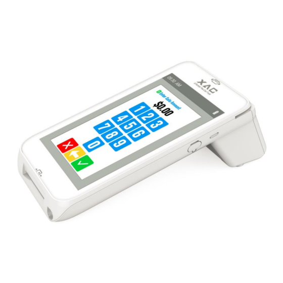
- Page 2 1. P ACKAGE ONTENT AT-170 Power adaptor USB cable Paper Roll (Optional) 2. D EVICE VERVIEW AT-170 Key Buttons & Interface Ports (Figure 1) FRONT REAR Right Side Figure 1 7” Touch Display RONT AREA Printer Paper Cover &...
- Page 3 This symbol is intended to alert the user before starting using the POS. Caution: Use only the AC adapter approved and provided by XAC Automation Corporation for use with this device. Use of any other AC adapter may cause a risk of fire or explosion.
- Page 4 Figure 3 5. U IC C SING THE EADER Insert an IC card into the slot with the chip side facing the same direction as the touch panel (Figure 4). Figure 4 6. U SING THE After inserting the chip card, Press the numeric key on virtual keypad (Figure 5) shown on the display to enter the password.
- Page 5 Figure 6 8. R EMOVE THE ATTERY STEP 1: Loose 2*screws and open the battery cover from bottom of AT-170 as Figure 7. STEP 2: After removing the bottom cover, pull up the battery connector as below Figure 8 to change a new battery.
- Page 6 Do not heat above 60 9. I NSERT CARD After removing the battery cover, the user can find SAM *2 (left) slots at the upper side of battery (Figure 9). Please insert the card correctly as the icon shown on the cover: Figure 9 10.
- Page 7 XAC Automation Corporation submitted SAR test results demonstrating compliance with the FCC’s SAR limit for wireless devices as part of the FCC’s equipment certification process for this device. These results can be accessed via the FCC’s equipment authorization database (found at http://transition.fcc.gov/oet/ea/fccid/) by searching for the device’s FCC ID:...
- Page 8 The above information is the exclusive intellectual property of XAC Automation Corporation and shall not be disclosed, distributed or reproduced without permission of XAC Automation Corporation. XAC AUTOMATION CORP. shall not be held liable for technical and editorial omissions or errors made herein;...
Need help?
Do you have a question about the XCL_AT-170 and is the answer not in the manual?
Questions and answers