Sign In
Upload
Manuals
Brands
Honeywell Manuals
Controller
DC1000 SERIES
Honeywell DC1000 SERIES Controller Manuals
Manuals and User Guides for Honeywell DC1000 SERIES Controller. We have
4
Honeywell DC1000 SERIES Controller manuals available for free PDF download: Product Manual, Program Configuration Manual
Honeywell DC1000 SERIES Product Manual (64 pages)
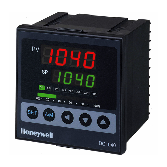
Digital Controller
Brand:
Honeywell
| Category:
Controller
| Size: 2 MB
Table of Contents
About this Document
3
Symbol Definitions
4
Table of Contents
5
Introduction
9
Overview
9
Installation
11
Overview
11
Condensed Specifications
12
Table 2-1 Condensed Specifications
12
Technical Data
12
Model Number Interpretation
15
Mounting
17
Physical Considerations
17
Overall Dimensions
17
Figure 2-1 Model DC1010 Dimensions
17
Figure 2-2 Model DC1020 Dimensions
17
Figure 2-3 Model DC1030 Dimensions
18
Figure 2-4 Model DC1040 Dimensions
18
Mounting Procedure
19
Figure 2-5 DC1050 / DC1060 Dimensions
19
Figure 2-6 Mounting Procedure
19
Wiring
20
Electrical Considerations
20
Wiring Diagrams
21
Identify Your Wiring Requirements
21
Making Terminal Connections
21
Wiring Diagrams
22
Figure 2-7 Model DC1010 Wiring
22
Figure 2-8 Model DC1020 Wiring
23
Figure 2-9 Model DC1030 Wiring
24
Figure 2-10 Model DC1040 Wiring
25
Figure 2-11 Model DC1050 Wiring
26
Figure 2-12 Model DC1060 Wiring
26
Operation
27
Overview
27
Operator Interface Overview
27
Figure 3-1 Operator Interface
27
Displays, Leds, and Keys
28
Table 3-1 Displays, Leds, and Keys
28
Mode Access
29
How to Move from One Mode to Another
29
Table 3-2 Mode Change Instructions
29
Figure 3-2 Mode Access Diagram
29
Operation Mode
30
Key Functions
30
Operation Mode Prompts
31
Table 3-3 Operation Mode Prompts
31
Control Types
32
Changing Set Point
34
Alarm Functions and Associated Prompts
35
HBA Functions and Associated Prompts
35
Configuration
36
Introduction
36
Configuration 1
36
Table 4-1 Configuration 1 Mode
36
Configuration 2
37
Table 4-2 Configuration 2 Mode
38
Alarms Configuration
42
Alarm Function Selections
42
Table 4-3 Alarm Function Selections
42
Deviation Alarm Overview
43
Figure 4-1 Deviation Alarms Operation
43
Figure 4-2 Deviation Alarms with HYSA(Hysterisis)
43
Figure 4-3 Upper Limit Deviation Alarm (Alarm Code 01)
43
Figure 4-4 Upper Limit Deviation Alarm (Alarm Code 11)
43
Figure 4-5 Lower Limit Deviation Alarm (Alarm Code 02)
44
Figure 4-6 Lower Limit Deviation Alarm (Alarm Code 12)
44
Figure 4-7 Dev. Band Breakaway Alarm (Alarm Code 03)
44
Figure 4-8 Dev. Band Breakaway Alarm (Alarm Code 13)
44
Figure 4-9 Deviation Band Alarm (Alarm Code 04)
44
Figure 4-10 Deviation Band Alarm (Alarm Code 14)
44
Absolute Value Alarm Overview
45
Figure 4-11 Absolute Value Alarm (with Relevant PV)
45
Figure 4-12 Absolute Upper Limit Alarm (Alarm Code 05)
45
Figure 4-13 Absolute Upper Limit Alarm (Alarm Code 15)
45
Figure 4-14 Absolute Lower Limit Alarm (Alarm Code 06)
45
Figure 4-15 Absolute Lower Limit Alarm (Alarm Code 16)
45
Program Alarm
46
System Alarm
46
Figure 4-16 Program RUN Alarm - Code 17
46
Figure 4-17 System Error Alarm - Code 08
46
Figure 4-18 System Error Alarm - Code 18
46
HBA (Heater Break Alarm)
47
Figure 4-19 HBA Operation - Code 09
47
Figure 4-20 HBA Wiring Diagram
48
Function Lock
49
Parameter Display SET (Hide or Display)
50
Overview
50
Functions of 'SET' Parameters
50
Table 4-4 Functions of Sets
50
Figure 4-21 Display Status
50
Input Codes
52
Code Selection
52
Table 4-5 Thermocouple Inputs
52
Table 4-6 RTD Inputs
52
Table 4-7 Linear Inputs
53
Input Type
53
Programmer (Optional)
54
Overview
54
Introduction
54
Programmer Terminologies
54
Operating Key Functions
54
Program Functions
54
Program Running Alarm
54
Table 5-1 Key Functions
54
Segment Runing Alarm
55
END Function
55
Linking Function
55
Wait Function
55
Other Functions
56
Table 5-2 Associated Program Functions
56
Program Configuration Prompts
57
Overview
57
Configuration
57
Table 5-3 Program Configuration Prompts
57
Program Example
60
Figure 5-1 Program Example
60
Error Codes
61
Overview
61
Table 6-1 Error Codes
61
Index
62
Advertisement
Honeywell DC1000 SERIES Product Manual (60 pages)
Digital Controller
Brand:
Honeywell
| Category:
Controller
| Size: 1 MB
Table of Contents
Table of Contents
5
1 Introduction
9
Overview
9
2 Installation
11
Overview
11
Condensed Specifications
12
Table 2-1 Condensed Specifications
12
Model Number Interpretation
14
Mounting
16
Physical Considerations
16
Overall Dimensions
16
Figure 2-1 Model DC1010 Dimensions
16
Figure 2-2 Model DC1020 Dimensions
16
Figure 2-3 Model DC1030 Dimensions
17
Figure 2-4 Model DC1040 Dimensions
17
Mounting Procedure
18
Figure 2-5 Mounting Procedure
18
Wiring
19
Electrical Considerations
19
Wiring Diagrams
20
Identify Your Wiring Requirements
20
Making Terminal Connections
20
Wiring Diagrams
21
Figure 2-6 Model DC1010 Wiring
21
Figure 2-7 Model DC1020, DC1025 Wiring
22
Figure 2-8 Model DC1030 Wiring
23
Figure 2-9 Model DC1040 Wiring
24
3 Operation
25
Overview
25
Operator Interface Overview
25
Figure 3-1 Operator Interface
25
Displays, Leds, and Keys
26
Table 3-1 Displays, Leds, and Keys
26
Mode Access
27
How to Move from One Mode to Another
27
Table 3-2 Mode Change Instructions
27
Figure 3-2 Mode Access Diagram
27
Operation Mode
28
Key Functions
28
Operation Mode Prompts
28
Table 3-3 Operation Mode Prompts
28
Control Types
29
Set Point
30
Alarm Functions and Associated Prompts
31
4 Configuration
32
Introduction
32
Configuration 1
32
Configuration 2
32
Table 4-1 Configuration 1 Mode
32
Table 4-2 Configuration 2 Mode
34
Alarms Configuration
37
Alarm Function Selections
37
Table 4-3 Alarm Function Selections
37
Deviation Alarm Overview
38
Figure 4-1 Deviation Alarms
38
Figure 4-2 Upper Limit Deviation Alarm
38
Figure 4-4 Lower Limit Deviation Alarm
39
Figure 4-6 Dev. Band Breakaway Alarm
39
Figure 4-7 Dev. Band Breakaway Alarm
39
Figure 4-8 Deviation Band Alarm
39
Figure 4-9 Deviation Band Alarm
39
Absolute Value Alarm Overview
40
Figure 4-10 Absolute Value Alarm
40
Figure 4-11 Absolute Upper Limit Alarm
40
Figure 4-13 Absolute Lower Limit Alarm
40
Program Alarm
41
System Alarm
41
Figure 4-15 Program RUN Alarm - Code 17
41
Figure 4-16 System Error Alarm - Code 08
41
Figure 4-17 System Error Alarm - Code 18
41
Function Lock
42
Parameter Display Set (Hide or Display)
43
Overview
43
Functions of Sets
43
Table 4-4 Functions of Sets
43
Figure 4-18 Display Status
43
Input Codes
45
Code Selection
45
Table 4-5 Thermocouple Inputs
45
Table 4-6 RTD Inputs
46
Table 4-7 Linear Inputs
47
5 Programmer (Optional)
49
Overview
49
Introduction
49
Programmer Terminologies
49
Operating Key Functions
49
Program Functions
49
Program Running Alarm
49
Table 5-1 Key Functions
49
Segment Completion Alarm
50
END Function
50
Linking Function
50
Wait Function
50
Other Functions
51
Table 5-2 Associated Program Functions
51
Program Configuration Prompts
52
Overview
52
Configuration
52
Table 5-3 Program Configuration Prompts
52
Program Example
55
Figure 5-1 Program Example
55
6 Error Codes
56
Overview
56
Table 6-1 Error Codes
56
7 Index
57
Honeywell DC1000 SERIES Product Manual (32 pages)
DIGITAL CONTROLLER
Brand:
Honeywell
| Category:
Controller
| Size: 0 MB
Table of Contents
Table of Contents
6
1 Overview
7
Introduction
7
2 Installation
8
Model Number Interpretation
8
Specification
9
Mounting
10
External Dimension
10
Dc1010
10
Dc1020
11
Dc1030
11
Dc1040
11
Wiring Diagrams
12
2.5.1 Dc1010
13
2.5.2 Dc1020
14
2.5.3 Dc1030
15
2.5.4 Dc1040
16
3 Configuration
17
Operator Interface
17
MODE Access
18
Modes
19
Operation
19
Configuration 1
20
Configuration 2
21
Alarms
23
Deviation Alarm
23
Absolute Value Alarm
24
Program Alarm
25
System Alarm
25
Function Lock
26
4 Input Codes
27
Thermocouples
27
Rtds
28
Linear Inputs
28
5 Operation
29
Type of Control
29
Manual Operation
29
ON/OFF Control
29
PID Control
29
Set Point
29
Alarm Set Point
29
6 Error Message
30
Advertisement
Honeywell DC1000 SERIES Program Configuration Manual (3 pages)
Brand:
Honeywell
| Category:
Controller
| Size: 0 MB
Table of Contents
Operation Mode
1
Program Mode
1
Set up Mode
1
Program Function
2
Terminologies
2
Operation
2
Key Functions
2
Program Alarm Functions
2
Link Function
2
Set Point for Segments and Program Settings
3
Start from Operation Mode
3
Back to Operation Mode
3
Advertisement
Related Products
Honeywell DCP552 Mark II
Honeywell DCP301
Honeywell DC3300
Honeywell dcp100t
Honeywell DCP 250
Honeywell DC33XB
Honeywell DB7110U1000
Honeywell DBC2000E1026
Honeywell DBC2000E2 Series
Honeywell DBC1500E1000-J
Honeywell Categories
Thermostat
Controller
Control Unit
Security Camera
Security System
More Honeywell Manuals
Login
Sign In
OR
Sign in with Facebook
Sign in with Google
Upload manual
Upload from disk
Upload from URL