
Related Manuals for Emerson OPM 3000


Summary of Contents for Emerson OPM 3000
- Page 1 Instruction Manual IM-105-3000, Rev 2.0 November 2008 OPM 3000 Opacity/Dust Density Monitor http://www.raihome.com...
- Page 3 HIGHLIGHTS OF CHANGES Effective November 12, 2008 Rev 2.0 Page Summary Page 1-6 Revised errant OPRL/Exit Correlation equation to read Lx/2Lt. Page 1-7 Revised final Code text to read Dust Density Calculation, 2 places. Page 2-1 Revised text of 3rd WARNING from ’power supply’ to ’power source’ for clarity. Page 2-5 Added introductory paragraph to Mechanical Installation topic.
-
Page 5: Table Of Contents
Specifications OPM 3000 System Features ......1-3 Normal Mode of Operation ....... 1-5 Specifications. - Page 6 Spare Parts ..........8-1 Spare Parts OPM 3000 Recommended Spare Parts ..... 8-1 APPENDIX A Overview .
-
Page 7: Essential Instructions
ESSENTIAL READ THIS PAGE BEFORE PROCEEDING! INSTRUCTIONS Emerson Process Management designs, manufactures and tests its products to meet many national and international standards. Because these instruments are sophisticated technical products, you MUST properly install, use and maintain them to ensure they continue to operate within their normal specifications. -
Page 8: Preface
PREFACE The purpose of this manual is to provide information concerning the components, functions, installation and maintenance of the OPM 3000. Some sections may describe equipment not used in your configuration. The user should become thoroughly familiar with the operation of this module before operating it. -
Page 9: Component Checklist
Specifications ........page 1-6 OPM 3000 - Ordering Information ....page 1-7... - Page 10 Instruction Manual IM-105-3000, Rev 2.0 OPM 3000 November 2008 Figure 1-1. Typical System Package (Sheet 1 of 2) In st ru ct IM -1 io n 05 -3 M an M ay 00 0 ua l 20 06 R ev .
-
Page 11: Opm 3000 System Features
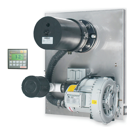
OPM 3000 System Transmissometer/Retro Reflector Features The OPM 3000 is a precision, double-pass, dual beam Transmissometer that consists of a transceiver (transmitter/receiver) mounted on one side of a stack or duct and a passive reflector mounted on the opposite side. The light source, photo detectors and all measurement/reference optics used in opacity measurement are housed in the transceiver. - Page 12 Cover Air Blower Control Unit Mounted in a control room environment, the OPM 3000 control unit provides instrument control functions (Section 4: Normal Operation for details). Optional Air Purge Weather Cover System The transceiver and reflector may be mounted in weather covers. The weather covers are fairly compact to allow movement around them even on a three-foot walkway or platform.
-
Page 13: Normal Mode Of Operation
Instruction Manual IM-105-3000, Rev 2.0 OPM 3000 November 2008 Normal Mode of The dual beam measurement system has a stack mounted transmissometer sensor system that consists of an optical transceiver mounted on one side of Operation the stack and a retro reflector mounted on the other (Figure 1-3). To avoid... -
Page 14: Specifications
Instruction Manual IM-105-3000, Rev 2.0 OPM 3000 November 2008 SPECIFICATIONS Specifications for the OPM 3000 system are listed in Table 1-1. Table 1-1. OPM 3000 Specifications OPM 3000 Specifications Control Unit Enclosure Panel mounted IP65/NEMA 4X Dimensions 3.8 in. x 3.8 in. -
Page 15: Opm 3000 - Ordering Information
Instruction Manual IM-105-3000, Rev 2.0 OPM 3000 November 2008 OPM 3000 - ORDERING Select complete model number from the Product Matrix, Table 1-2. INFORMATION Table 1-2. Product Matrix OPM3000 Opacity/Dust Density Monitor Non-compliant Code Intelligent Electronics Basic Unit – Digital Display, (2) 4-20 mA Outputs, (4) Alarm PNP’s, RS 232/485, Modbus... -
Page 16: Im-105-3000, Rev
Instruction Manual IM-105-3000, Rev 2.0 OPM 3000 November 2008... -
Page 17: Overview
• Considerations prior to installation. • Mechanical installation procedures, including the applicable drawings and pictures to assist in the process. • Wiring requirements for the OPM 3000 system. • The beam alignment procedure. • Output connections for alarms and recording devices. -
Page 18: Installation Considerations
OPM 3000 November 2008 INSTALLATION CONSIDERATIONS Choose an Installation The primary considerations for choosing a site for the OPM 3000 are accessibility, ambient environmental conditions, and obtaining a Site representative sample of the process. The following general guidelines should be considered. - Page 19 Instruction Manual IM-105-3000, Rev 2.0 OPM 3000 November 2008 Figure 2-1. Installation Clearances and Weather Cover Dimensions...
-
Page 20: Regulatory/Process Considerations
Instruction Manual IM-105-3000, Rev 2.0 OPM 3000 November 2008 Regulatory/Process The EPA has established the following guidelines for choosing an opacity/dust density monitor installation site: Considerations 1. Locate the transmitter across a section of a duct or stack that will provide a particulate matter flow through the path of the transmitter beam representative of the duct or stack flow. -
Page 21: Mechanical Installation
Instruction Manual IM-105-3000, Rev 2.0 OPM 3000 November 2008 MECHANICAL Observe the following instructions and guidelines when installing the OPM 3000 transceiver and retro reflector at the stack. INSTALLATION NOTE The beam of the instrument must be kept in a horizontal plane; the transceiver cannot be rotated more than ±10... - Page 22 Instruction Manual IM-105-3000, Rev 2.0 OPM 3000 November 2008 NOTE An alignment tool can be purchased from the factory to ensure accurate alignment. 3. Attach the alignment tool to the pipe flange assembly and insert the assembly into the 3-1/2 in. (89 mm) hole in the stack wall.
- Page 23 Instruction Manual IM-105-3000, Rev 2.0 OPM 3000 November 2008 Figure 2-3. Mounting the Stack Flanges STACKS UNDER 6 FEET ACROSS 6 in. - 8 in. 3 in. Sch 40 (152 - 203 mm) Mounting Nipple VERTICAL AXIS 2-1/2 in. (64 mm)
- Page 24 Instruction Manual IM-105-3000, Rev 2.0 OPM 3000 November 2008 Figure 2-4. Stack Flange Installation...
-
Page 25: Mounting The Air Plenum And Weather Covers
(Figure 2-6). Place the transceiver and retro reflector in a safe place. 3. If the OPM 3000 is equipped with weather covers, remove the two weather cover hood hinge pins located on the upper right and left hand corner of the hood. -
Page 26: Attach Blowers
Instruction Manual IM-105-3000, Rev 2.0 OPM 3000 November 2008 Attach Blowers With Dual Blowers Connect an air blower to the air blower port on the transceiver using the air hoses and clamps. Connect the other air blower to the air blower port on the retro reflector using the air hoses and clamps. -
Page 27: Mounting The Transceiver And Retro Reflector
Instruction Manual IM-105-3000, Rev 2.0 OPM 3000 November 2008 Mounting the Use the following procedure to mount the air transceiver and retro reflector. Transceiver and Retro NOTE Reflector The installation procedures below are for both the transceiver and the retro reflector. - Page 28 Instruction Manual IM-105-3000, Rev 2.0 OPM 3000 November 2008 Figure 2-7. Mounting Brackets Mounting Bracket Mounting Bracket Figure 2-8. Control Unit Installation 0.197 in. max. (5 mm max.) 0.244 in. (8,2 mm) 2.52 in. (64 mm) 2-12...
-
Page 29: Wiring Installation
OPM 3000 November 2008 WIRING INSTALLATION Use the following procedure to install the OPM 3000 system wiring. ELECTRICAL SHOCK HAZARD Disconnect and lock out all power before wiring the system. Failure to lock out power may cause serious injury or death. - Page 30 Instruction Manual IM-105-3000, Rev 2.0 OPM 3000 November 2008 Figure 2-9. Wiring Diagram 2-14...
-
Page 31: Output Connections
Instruction Manual IM-105-3000, Rev 2.0 OPM 3000 November 2008 Output Connections Refer to Figure 2-9. Channel #1, 0-100% Opacity 4-20 mA Output to Recording Devices The maximum device load for the 4-20 mA current loop is 500 ohms. 1. Connect the negative (-) wire from your device to terminal 0V on the bottom connector of the control unit. -
Page 32: Rs485 Communications
Instruction Manual IM-105-3000, Rev 2.0 OPM 3000 November 2008 Do not apply input voltage to alarm output terminals O2 through O7. Applying an external voltage to one or more of these terminals will damage the equipment. NOTE Make sure the jumper from the +V terminal on the top connector to the +V terminal on the bottom connector is connected. -
Page 33: Overview
OPM 3000 system has been verified. 4. To start up the OPM 3000 apply 115 VAC and 24 VDC power to the control unit. Observe the control unit display for indications of proper equipment operation. -
Page 34: Beam Alignment Procedure
Instruction Manual IM-105-3000, Rev 2.0 OPM 3000 November 2008 BEAM ALIGNMENT Use the following procedure to align the beam. PROCEDURE NOTE The control unit does not have to be connected or powered to perform an alignment. For alignment accuracy the stack should be at normal temperature. -
Page 35: Stack / Exit Correlation
1.0, the exit opacity will be greater than the opacity at the instrument location. The OPM 3000 uses this correction factor to calculate the stack exit opacity. It is not practical to have an Lx/Lt factor much greater than 2.0 because the error of the instrument increases as Lx/Lt becomes greater. -
Page 36: Initial Adjustments
Before adjusting the OPM 3000 verify the following conditions: • The boiler or process is shut down and a clear stack condition exists (if not, use the optional OPM 3000 test flange kit.) • Power is disconnected whenever removing or replacing the transceiver housing. - Page 37 Instruction Manual IM-105-3000, Rev 2.0 OPM 3000 November 2008 Figure 3-3. Zero and Span Adjustments PT-1 (Zero) PT-3 (Span) NOTE If attempting an alignment without the optional zero jig please call our Customer Support Center at 1-800-433-6076. 5. Swing open the transceiver and attach the zero jig by placing it on the alignment pins and secure it to the transceiver with the thumb screw.
- Page 38 Instruction Manual IM-105-3000, Rev 2.0 OPM 3000 November 2008...
-
Page 39: Overview
• Operation of the OPM 3000 through the control unit. • How to edit the password parameters. The operating procedures in this section apply to the OPM 3000 when used for setup and calibration of the instrument for opacity measurements. When... -
Page 40: About Page
Instruction Manual IM-105-3000, Rev 2.0 OPM 3000 November 2008 About Page To access the About page: 1. Scroll up using button (#1 ) or down using button (#6 ) to select About (Figure 4-2). Figure 4-2. About Page ↵ 2. Press the enter button ( ) to access the first page (Figure 4-3) of the About display screens. - Page 41 Instruction Manual IM-105-3000, Rev 2.0 OPM 3000 November 2008 4. Press the button to toggle to the second About display screen (Figure 4-4). This page contains the Sensor loc ID, Flange to flange measurement and the OPLR (Optical Path Length Ratio).
-
Page 42: Setup Of Password Protected Parameters
Instruction Manual IM-105-3000, Rev 2.0 OPM 3000 November 2008 Setup of Password 1. From any screen press ESC until the Main, Setup and About home screen is visible. Protected parameters 2. Scroll down to Setup using the (#6 ) button. -
Page 43: Off Stack Zero Calibration
Instruction Manual IM-105-3000, Rev 2.0 OPM 3000 November 2008 OFF STACK ZERO This procedure may be used if: CALIBRATION • A clear stack condition is not possible, and the zero appears to be incorrect. • The flange to flange distance on site is different than the original factory set up. - Page 44 Instruction Manual IM-105-3000, Rev 2.0 OPM 3000 November 2008...
-
Page 45: Overview
Instruction Manual IM-105-3000, Rev 2.0 OPM 3000 November 2008 Section 5 Zero Jig and Neutral Density Filter Overview ........page 5-1 Using the Zero Jig . -
Page 46: Installation
Instruction Manual IM-105-3000, Rev 2.0 OPM 3000 November 2008 Installation The zero jig (Figure 5-1) on-line test reflector is inserted over the transceiver lens. The filters provided are marked in single-pass opacity; this is the same as double-pass with a correlation factor (OPLR) of 0.50. - Page 47 IM-105-3000, Rev 2.0 OPM 3000 November 2008 Figure 5-2. Zero Jig Installation Mounting Screw Alignment Pin Alignment Pin Iris Note: The zero arm, located below the iris on the transceiver, is not included with the OPM 3000. Fine Adjustment (Large Knob)
-
Page 48: Coarse Adjustments
Instruction Manual IM-105-3000, Rev 2.0 OPM 3000 November 2008 Coarse Adjustments Opacity Below Zero If the opacity reading is below zero and you can not reach zero after you have turned the adjustment knob as far as it will go into the zero jig housing, perform the following procedure: Do not force the knob. -
Page 49: Filter Correction
Specification 1, Section 7.1.3 Attenuation Calibration. Filter Certification QA/QC testing by Emerson Process Management of the filters at an interval of not more than 6 months is recommended. Filter certification, replacement, or additional neutral density filters are available from Emerson Process Management. - Page 50 Instruction Manual IM-105-3000, Rev 2.0 OPM 3000 November 2008...
-
Page 51: Overview
OVERVIEW This section describes the routine maintenance of the Rosemount Analytical OPM 3000 Opacity/Dust Density Monitor. The amount of maintenance required depends on the environment to which the instrument is subjected. A unit that is subjected to extremely dusty conditions, vibration, and movement will require considerably more maintenance than a unit that is rigidly mounted in a clean, dust-free atmosphere. -
Page 52: Preventive Maintenance Schedule
Instruction Manual IM-105-3000, Rev 2.0 OPM 3000 November 2008 PREVENTIVE MAINTENANCE Item to Check Frequency Procedure Zero/Span Daily Check that readings are within specification (±2%), SCHEDULE refer to Section 3: Startup and Calibration. Beam alignment Monthly or Clean and adjust as necessary, refer to "Output as required Connections"... -
Page 53: Corrective Maintenance
6. Install new lamp assembly in the lamp holding fixture and tighten set screws. 7. Install lamp holding fixture and secure with the two socket head cap screws. Connect J2. 8. Calibrate the OPM 3000 per Section 3: Startup and Calibration. 9. Install cover. Figure 6-1. Lamp/Bulb Removal... -
Page 54: Transceiver Fuse Replacement
Instruction Manual IM-105-3000, Rev 2.0 OPM 3000 November 2008 Transceiver Fuse 1. Remove the transceiver cover by removing the screw below the target viewing window and pulling the housing straight back until it clears the Replacement optical plate. 2. Pull fuse (F1) from the clamp (Figure 6-2). -
Page 55: Circuit Board Replacement
3. Remove the four nuts (Figure 6-3) from the screw posts holding the signal processor board in place. 4. Install new signal processor board. Install wiring removed in step 2. 5. Calibrate the OPM 3000 per Section 3: Startup and Calibration. 6. Install cover. Figure 6-3. Circuit Board... - Page 56 3. Remove the four socket head cap screws (Figure 6-4) with an allen wrench to take off the power/modulator board. 4. Install new power/modulator board. Install wiring removed in step 2. 5. Calibrate the OPM 3000 per Section 3: Startup and Calibration. 6. Install cover. Figure 6-4. Power/Modulator...
-
Page 57: Troubleshooting
Instruction Manual IM-105-3000, Rev 2.0 OPM 3000 November 2008 Section 7 Troubleshooting Troubleshooting ....... . . page 7-1 Removing covers from the optical assembly or making optical repairs or adjustments in an unsuitable environment can affect the accuracy of the unit. - Page 58 Instruction Manual IM-105-3000, Rev 2.0 OPM 3000 November 2008...
-
Page 59: Spare Parts
Spare Parts ........page 8-1 SPARE PARTS Contact an Emerson Process Management sales department with the serial number of your instrument and they will make recommendations based on your system. - Page 60 Instruction Manual IM-105-3000, Rev 2.0 OPM 3000 November 2008...
-
Page 61: Overview
Transmissometers are used throughout the world for continuous monitoring of opacity and particulate concentrations (also known as ‘Dust Density’). The OPM 3000 Opacity/Dust Density Monitor when factory-equipped with the mg/m dust density option provides continuous and reliable measurements of particulate concentrations in the stack. - Page 62 Instruction Manual IM-105-3000, Rev 2.0 OPM 3000 November 2008 Figure A-1 illustrates a calibration curve developed for a cement kiln equipped with an electrostatic precipitator. The 95% tolerance intervals at the 95% confidence level are indicated. Figure A-1. Typical Regression -...
- Page 63 Instruction Manual IM-105-3000, Rev 2.0 OPM 3000 November 2008 Figure A-3 shows a similar calibration curve obtained on a lignite-fired boiler, and Figure A-4 shows a calibration curve for a bituminous coal fired power station. Figure A-3. Typical Regression - Lignite Fired Boiler Emissions Figure A-4.
- Page 64 Instruction Manual IM-105-3000, Rev 2.0 OPM 3000 November 2008 c. Type 2 error is the 95% confidence level that the next single observation will fall within the limit. d. Type 3 error is the 95% confidence level that 95% of all possible observations (95% tolerance) will fall within the limit.
-
Page 65: Calibration
Instruction Manual IM-105-3000, Rev 2.0 OPM 3000 November 2008 CALIBRATION Calibration for dust density monitoring must be performed before the corrected mg/m data display and instrument output signals can be used. In typical dust monitoring applications proper instrument calibration is verified approximately once per year. - Page 66 Instruction Manual IM-105-3000, Rev 2.0 OPM 3000 November 2008 6. When finished press the ESC button until you display the Main, Setup, About page (Figure A-6). 7. Press the enter key ↵ while the cursor arrow is pointing to Main to access the opacity/mg display page (Figure A-7).
-
Page 67: Example After The Stack Test
Instruction Manual IM-105-3000, Rev 2.0 OPM 3000 November 2008 10. Using the test data recorded in step 9, draw a line from 0,0 to the point (OD, mg). The graph can now be used to calibrate the mg/m output and is valid until the user changes the source characteristics. -
Page 68: Mg/M3 Operation
IM-105-3000, Rev 2.0 OPM 3000 November 2008 MG/M OPERATION Some differences exist among the operating displays when the OPM 3000 with the mg/m option is used. The following paragraphs describe control features unique to the mg/m option. Display and Output There are two pages to the main display;... -
Page 69: Setup Of Password Protected Parameters
Instruction Manual IM-105-3000, Rev 2.0 OPM 3000 November 2008 Setup of Password 1. From any screen press ESC until the Main, Setup and About home screen is displayed. Protected Parameters 2. Scroll down to Setup using the (#6 ) button. -
Page 70: Modbus Polling
MODBUS Polling MODBUS polling allows the user to view MODBUS communication device addresses in use for the OPM 3000 with the dust density option. To read the value of a register number use the register number plus 40,001. To read the status of a relay use the coil number. - Page 71 Instruction Manual IM-105-3000, Rev 2.0 OPM 3000 November 2008 Appendix B Safety Data Safety Instructions ........page B-2...
-
Page 72: Safety Instructions
Instruction Manual IM-105-3000, Rev 2.0 OPM 3000 November 2008 IMPORTANT SAFETY INSTRUCTIONS SAFETY INSTRUCTIONS FOR THE WIRING AND INSTALLATION OF THIS APPARATUS The following safety instructions apply specifically to all EU member states. They should be strictly adhered to in order to assure compliance with the Low Voltage Directive. - Page 73 Instruction Manual IM-105-3000, Rev 2.0 OPM 3000 November 2008 DŮLEŽITÉ Bezpečnostní pokyny pro zapojení a instalaci zařízení Následující bezpečnostní pokyny se speciálně vztahují na všechny členské státy EU. Pokyny by měly být přísně dodržovány, aby se zajistilo splnění Směrnice o nízkém napětí. Pokud nejsou pokyny nahrazeny místními či národními normami, měly by je dodržovat i...
- Page 74 Instruction Manual IM-105-3000, Rev 2.0 OPM 3000 November 2008 VIGTIGT Sikkerhedsinstruktion for tilslutning og installering af dette udstyr. Følgende sikkerhedsinstruktioner gælder specifikt i alle EU-medlemslande. Instruktionerne skal nøje følges for overholdelse af Lavsspændingsdirektivet og bør også følges i ikke EU-lande medmindre andet er specificeret af lokale eller nationale standarder.
- Page 75 Instruction Manual IM-105-3000, Rev 2.0 OPM 3000 November 2008 BELANGRIJK Veiligheidsvoorschriften voor de aansluiting en installatie van dit toestel. De hierna volgende veiligheidsvoorschriften zijn vooral bedoeld voor de EU lidstaten. Hier moet aan gehouden worden om de onderworpenheid aan de Laag Spannings Richtlijn (Low Voltage Directive) te verzekeren.
- Page 76 Instruction Manual IM-105-3000, Rev 2.0 OPM 3000 November 2008 BELANGRIJK Veiligheidsinstructies voor de bedrading en installatie van dit apparaat. Voor alle EU lidstaten zijn de volgende veiligheidsinstructies van toepassing. Om aan de geldende richtlijnen voor laagspanning te voldoen dient men zich hieraan strikt te houden. Ook niet EU lidstaten dienen zich aan het volgende te houden, tenzij de lokale wetgeving anders voorschrijft.
- Page 77 Instruction Manual IM-105-3000, Rev 2.0 OPM 3000 November 2008 WICHTIG Sicherheitshinweise für den Anschluß und die Installation dieser Geräte. Die folgenden Sicherheitshinweise sind in allen Mitgliederstaaten der europäischen Gemeinschaft gültig. Sie müssen strickt eingehalten werden, um der Niederspannungsrichtlinie zu genügen.
- Page 78 Instruction Manual IM-105-3000, Rev 2.0 OPM 3000 November 2008 ΣΗΜΑΝΤΙΚΟ Οδηγιεσ ασφαλειασ για την καλωδιωση και εγκατασταση τησ συσκευησ Οι ακόλουθες οδηγίες ασφαλείας εφαρµόζονται ειδικά για όλες τις χώρες µέλη της Ευρωπαϊκής Κοινότητας. Θα πρέπει να ακολουθούνται αυστηρά ώστε να εξασφαλιστεί η συµβατότητα µε τις οδηγίες για τη Χαµηλή Τάση.
- Page 79 Instruction Manual IM-105-3000, Rev 2.0 OPM 3000 November 2008 OLULINE TEAVE Juhtmestiku ja seadme paigaldamisega seotud ohutusjuhised Alljärgnevad ohutusjuhised rakenduvad eriti kõigi Euroopa Liidu liikmesriikide suhtes. Antud juhiseid tuleb täpselt järgida, et kindlustada vastavus madalpinge direktiiviga. Euroopa Liitu mittekuuluvad riigid peavad samuti alljärgnevaid juhiseid järgima, va juhul, kui on olemas...
- Page 80 Instruction Manual IM-105-3000, Rev 2.0 OPM 3000 November 2008 TÄRKEÄÄ Turvallisuusohje, jota on noudatettava tämän laitteen asentamisessa ja kaapeloinnissa. Seuraavat ohjeet pätevät erityisesti EU:n jäsenvaltioissa. Niitä täytyy ehdottomasti noudattaa jotta täytettäisiin EU:n matalajännitedirektiivin (Low Voltage Directive) yhteensopivuus. Myös EU:hun kuulumattomien valtioiden tulee nou-dattaa tätä...
- Page 81 Instruction Manual IM-105-3000, Rev 2.0 OPM 3000 November 2008 IMPORTANT Consignes de sécurité concernant le raccordement et l'installation de cet appareil. Les consignes de sécurité ci-dessous s'adressent particulièrement à tous les états membres de la communauté européenne. Elles doivent être strictement appliquées afin de satisfaire aux directives concernant la basse tension.
- Page 82 Instruction Manual IM-105-3000, Rev 2.0 OPM 3000 November 2008 FONTOS Biztonsági előírások a készülék vezetékeléséhez és üzembeállításához A következő biztonsági előírások kifejezetten vonatkoznak az összes EU-tagállamra. Ezeket szigorúan be kell tartani a Kisfeszültségű irányelvnek való megfelelés biztosításához. A nem EU-tagállamok szintén tartsák be a következőket, kivéve ha a helyi és nemzeti...
- Page 83 Instruction Manual IM-105-3000, Rev 2.0 OPM 3000 November 2008 IMPORTANTE Norme di sicurezza per il cablaggio e l'installazione dello strumento. Le seguenti norme di sicurezza si applicano specificatamente agli stati membri dell'Unione Europea, la cui stretta osservanza è richiesta per garantire conformità...
- Page 84 Instruction Manual IM-105-3000, Rev 2.0 OPM 3000 November 2008 SVARBU š io prietaiso laidų prijungimo ir instaliacijos saugos instrukcijos Toliau išvardinti saugumo reikalavimai taikomi konkrečiai visoms ES šalims narėms. Jų turi būti griežtai paisoma, kad būtų užtikrintai laikomasi Žemos įtampos direktyvos. Ne ES narės taip pat turi laikytis toliau pateikiamų...
- Page 85 Instruction Manual IM-105-3000, Rev 2.0 OPM 3000 November 2008 SVARĪGI Droš ības norādījumi š īs iekārtas pievienoš anai un uzstādīš anai Turpmākie drošības norādījumi attiecas uz visām ES dalībvalstīm. Tie ir stingri jāievēro, lai nodrošinātu atbilstību Zemsprieguma direktīvai. Turpmāk norādītais jāievēro arī valstīs, kas nav ES dalībvalstis, ja vien šos norādījumus neaizstāj vietējie vai valsts standarti.
- Page 86 Instruction Manual IM-105-3000, Rev 2.0 OPM 3000 November 2008 IMPORTANTI STRUZZJONIJIET TAS-SIGURTÀ GĦALL-WIRING U L-INSTALLAZZJONI TAT-TAGĦMIR L-istruzzjonijiet tas-sigurtà japplikaw speċifikament għall-Istati Membri ta' l-UE. Dawn għandhom jiġu osservati b'mod strett biex tkun żgurata l- konformità mad-Direttiva dwar il-Vultaġġ Baxx. Stati li mhumiex membri ta' l-UE għandhom ukoll ikunu konformi ma' dan li ġej ħlief jekk dawn ikunu...
- Page 87 Instruction Manual IM-105-3000, Rev 2.0 OPM 3000 November 2008 VIKTIG Sikkerhetsinstruks for tilkobling og installasjon av dette utstyret. Følgende sikkerhetsinstruksjoner gjelder spesifikt alle EU medlemsland og land med i EØS-avtalen. Instruksjonene skal følges nøye slik at installasjonen blir i henhold til lavspenningsdirektivet. Den bør også...
- Page 88 Instruction Manual IM-105-3000, Rev 2.0 OPM 3000 November 2008 WAŻNE! Zalecenia dotyczące bezpieczeństwa w zakresie podłączania i instalacji tego urządzenia Następujące zalecenia dotyczą zwłaszcza stosowania urządzenia we wszystkich krajach Unii Europejskiej. Należy się ściśle do nich stosować w celu zapewnienia zgodności z dyrektywą niskonapięciową.
- Page 89 Instruction Manual IM-105-3000, Rev 2.0 OPM 3000 November 2008 IMPORTANTE Instruções de segurança para ligação e instalação deste aparelho. As seguintes instruções de segurança aplicam-se especificamente a todos os estados membros da UE. Devem ser observadas rigidamente por forma a garantir o cumprimento da Directiva sobre Baixa Tensão.
- Page 90 Instruction Manual IM-105-3000, Rev 2.0 OPM 3000 November 2008 DÔLEŽITÉ Bezpečnostné pokyny pre zapojenie káblov a inš taláciu tohto prístroja Nasledovné bezpečnostné pokyny sa vzt’ahujú konkrétne na všetky členské štáty EÚ. Musia byt’ striktne dodržané, aby sa zaistila zhoda so Smernicou o nízkom napätí.
- Page 91 Instruction Manual IM-105-3000, Rev 2.0 OPM 3000 November 2008 POMEMBNO Varnostna navodila za povezavo in vgradnjo naprave Naslednja varnostna navodila veljajo za vse države članice EU. Zaradi zagotovitve skladnosti z nizkonapetostno direktivo morate navodila strogo upoštevati. V državah, ki niso članice EU, je treba upoštevati tudi naslednje smernice, razen če jih ne zamenjujejo lokalni ali nacionalnimi...
- Page 92 Instruction Manual IM-105-3000, Rev 2.0 OPM 3000 November 2008 IMPORTANTE Instrucciones de seguridad para el montaje y cableado de este aparato. Las siguientes instrucciones de seguridad, son de aplicacion especifica a todos los miembros de la UE y se adjuntaran para cumplir la normativa europea de baja tension.
- Page 93 Instruction Manual IM-105-3000, Rev 2.0 OPM 3000 November 2008 VIKTIGT Säkerhetsföreskrifter för kablage och installation av denna apparat. Följande säkerhetsföreskrifter är tillämpliga för samtliga EU-medlemsländer. De skall följas i varje avseende för att överensstämma med Lågspännings direktivet. Icke EU medlemsländer skall också...
- Page 94 Instruction Manual IM-105-3000, Rev 2.0 OPM 3000 November 2008 B-24...
-
Page 95: Returning Material
RETURNING MATERIAL If factory repair of defective equipment is required proceed as follows: 1. Secure a return authorization from an Emerson Process Management Sales Office or Representative before returning the equipment. Equipment must be returned with complete identification in accordance with Emerson Process Management instructions or it will not be accepted. - Page 96 Instruction Manual IM-105-3000, Rev 2.0 OPM 3000 November 2008...
- Page 97 Instruction Manual IM-105-3000, Rev 2.0 OPM 3000 November 2008 Index Installation About Page ....4-2 Recommended Spare Parts . . .8-1 Control Unit ... 2-11 Accessibility .
- Page 98 Instruction Manual IM-105-3000, Rev 2.0 OPM 3000 November 2008 Index-2...
- Page 99 WARRANTY Rosemount Analytical warrants that the equipment manufactured and sold by it will, upon shipment, be free of defects in workmanship or material. Should any failure to conform to this warranty become apparent during a period of one year after the date of shipment, Rosemount Analytical shall, upon prompt written notice from the purchaser, correct such nonconformity by repair or replacement, F.O.B.
- Page 100 T 65 6 777 8211 T 44 1243 863121 T 44 1243 863121 F 713 827 3329 F 65 6 777 0947 F 44 1243 845354 F 44 1243 845354 E analytical@ ap.emerson.com http://www.raihome.com http://www.raihome.com © 2008 Emerson Process Management. All rights reserved.
Need help?
Do you have a question about the OPM 3000 and is the answer not in the manual?
Questions and answers