Table of Contents
Advertisement
Quick Links
Advertisement
Table of Contents

Related Manuals for Emerson DIXELL iPro Series


Summary of Contents for Emerson DIXELL iPro Series
- Page 1 iPro SERIES (v.3.5)
-
Page 2: Important Recommendations
IMPORTANT RECOMMENDATIONS The symbol alerts the user of non-insulated “dangerous voltage” within the product area that is sufficiently high to constitute a risk of electric shock to persons. The symbol alerts the user of important operating and maintenance (assistance) instructions found in the documentation attached to the device. -
Page 3: Product Disposal (Weee)
Prevent the device from being dropped, knocked or shaken as either can cause irreparable damage. Do not clean the device with corrosive chemical products, solvents or aggressive detergents. The device must not be used in applications that differ from that specified in the following material. -
Page 4: General Specifications
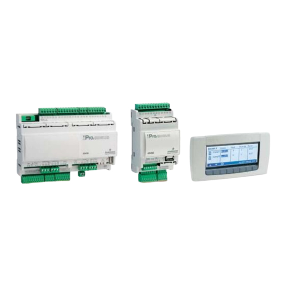
INTRODUCTION The iPRO is the range of programmable controllers manufactured by Dixell. The range consists of programmable controllers, I/O expansions, drivers for electronic valves and graphical interfaces adapted to cover any type of application in the air-conditioning sector, cooling sector and any relative area. - Page 5 • Connection to the dedicated remote LCD display. • CANBus. • RS485 Master. • RS485 Slave. The remote LCD display has the following features: • 240x96 pixel LCD graphic display. • 32-bit processor. • Multilingual in ASCII or UNICODE version. •...
- Page 6 IPRO 4 DIN (IPG100D – IPG200D – IPC100E RANGES) 1592025700 IPROFAMILY 3.5 stp GB 2016.12.07 iPro Series 37/96...
- Page 7 4.5.1 Description of the connections Connector Description Connector for 24Vac/dc power supply Analogue inputs (Pb1 - Pb6, PbC) Additional power (+5Vdc, +12Vdc, GND) Analogue outputs (Out1 - Out4, GND) 24Vac/dc digital inputs (DI1 - DI11, GND) Connector for remote terminal (VISOGRAPH), maximum 1 terminal per iPRO. RS485 Slave connector Serial port connector (LAN or RS485) USB port for downloads (BIOS, ISaGRAF®...
- Page 8 DI11 Digital input Potential free (free from voltage) Reference “-“ for digital inputs from1 to 11 (if version with dry contacts, this input has GND(-) to be used only as common for the digital inputs) Common relays 1, 2, 3 and 4 (MAX 10A) Common relays 1, 2, 3 and 4 (MAX 10A) Relay 1 normally open contact Relay 2 normally open contact...
- Page 9 4.5.3.3 Analogue outputs Type: Non opto-insulated internal power Number of outputs: Type of analogue output: 4 configurable outputs 0-10Vdc 4-20mA (Out1 - Out4) (configurable via software parameter) Maximum load: 40mA (Out1 - Out4) max with configured outputs 0-10Vdc 400Ω max with configured outputs 4-20mA 22Ω...
- Page 10 4.5.3.6 Mechanical specifications 4 DIN module 4.5.3.7 Electrical specifications Power Supply: 24Vac +10/-15%, 50/60Hz 20 - 36Vdc Consumption: from 30VA (Vac), from 25W (Vdc) Connectors: Molex connectors with low voltage wiring (for IPG100D) Phoenix quick coupling connectors for low voltage (for IPG200D) STELVIO 90°...
-
Page 11: Expansion Modules
MEANING OF THE LEDS AND JUMPERS IN THE VARIOUS DEVICES PROGRAMMABLE CONTROLLERS LEDs are present in the programmable controllers in order to indicate the status of the device. PWR ON (green): PWR ON - if on, the device is powered LED1 (yellow): - if on, the system is being updated. -
Page 12: Installation
INSTALLATION The devices must not be installed in environments where the following situations are present: Temperature and humidity outside the range stipulated in the data plate. Frequent and sudden changes in temperature and/or humidity Direct sunlight and weathering in general ... - Page 13 CONNECTION OF THE ANALOGUE INPUTS The analogue inputs in the programmable controllers and expansions are fully configurable. NTC or PTC, 0 - 20mA, 4 - 20mA, 0 - 10V, 0 - 1V or 0 - 5V type of sensors can be used. The analogue inputs can also be used as digital inputs (potential free - not live).
- Page 14 7.3.3 Pressure transducers and current probes (0 - 20mA, 4 - 20mA) 2-row sensors that require +12Vdc power supply. Each sensor must be connected through one of the inputs (from Pb1 to Pb10) and the power supply (+12V) as shown in the diagram below. IPG-IPC IPG-IPC 4 DIN Recommendations:...
- Page 15 7.3.5 Pressure transducers and ratiometric pressure transducers (0 - 5V) 3-row sensors that require +5Vdc power supply. Each sensor must be connected through one of the inputs (from Pb1 to Pb10) and the power supply (+5V/GND) as shown in the diagram below. IPG-IPC IPG-IPC 4 DIN Recommendations:...
- Page 16 7.3.7 Live probes (0 - 1V, 0 - 5V, 0 - 10V) 3-row sensors that require +12Vdc power supply. Each sensor must be connected through one of the inputs (from Pb1 to Pb10) and the power supply (+12V/GND) as shown in the diagram below. IPG-IPC IPG-IPC 4 DIN Recommendations:...
- Page 17 7.3.9 Probes and transducers with 24Vac/dc power supply 3 or 4-row sensors that require +24Vac/dc power supply Each sensor must be connected through one of the inputs (from Pb1 to Pb10), whereas the power supply as shown in the diagram below. This is an example for versions IPG-IPC.
- Page 18 7.3.10 Probes and transducers with 24Vac/dc power supply IPG800 Series 3 or 4-row sensors that require +24Vac/dc power supply Each sensor must be connected through one of the inputs (from Pb6 to Pb7), whereas the power supply as shown in the diagram below. Recommendations: - respect the “+”...
-
Page 19: Connection Of The Digital Inputs
CONNECTION OF THE DIGITAL INPUTS The digital inputs in the programmable controllers and expansions are fully configurable. Depending on the model used, the digital inputs can be used as potential free or live (24Vac/dc) digital inputs. 7.4.1 Potential-free digital inputs IPG100, IPC100 and IPX106D versions IPG200, IPX125D, IPX115D, IPX215D, IPX215D VERSIONS IPG108D, IPG208D VERSION (special version not standard version) - Page 20 CONNECTION OF THE ANALOGUE OUTPUTS Depending on the model and configurations, it is possible to use analogue outputs such as 0 - 10Vdc, 4 - 20mA or PWM (the PWM configuration requires the Dixell XVxx module to be used for the fan speed to be controlled).
- Page 21 7.5.2 0-10Vdc, 4-20mA Analogue output for fan speed control IPG800 Series The three analog outputs AO1, AO2 and AO3 can be used to drive an external fan speed control (Dixell XV series) through the 0-10Vdc or 4-20mA. Recommendations: - follow the diagram of the device used, for the numbering. - the configuration is determined by the application.
- Page 22 7.5.4 PWM analogue output for control IPG800 Series The analog outputs AO1 (depend on the model), can be used to drive an external fan speed control (Dixell XV series) through the PWM signal. Note: the PWM is available only if the Power Supply is 24Vac. Recommendations: - follow the diagram of the device used, for the numbering.
- Page 23 7.5.6 Devices with 24Vac/dc power supply 3 or 4-row devices that require +24Vac/dc power supply Each device must be connected through one of the outputs (from Out1 to Out6), whereas the power supply as shown in the diagram below. This is an example for versions IPG-IPC. For all the others version, verify the correct number of the pin in the connector.
-
Page 24: Connection Of The Digital Outputs
7.5.7 Analogue output for relays (coil power supply 12Vdc) IPG-IPC IPG 4 DIN Recommendations: - follow the diagram of the device used, for the numbering. - the configuration is determined by the application. CONNECTION OF THE DIGITAL OUTPUTS Depending on the model, the digital outputs can have different connection specifications. The relays have been split into groups, each with a separate common. -
Page 25: Canbus Connection
CANBUS CONNECTION Recommendations: - follow the diagram of the device used, for the numbering. 1592025700 IPROFAMILY 3.5 stp GB 2016.12.07 iPro Series 93/96... - Page 26 RS485 SLAVE CONNECTIONS Recommendations: - follow the diagram of the device used, for the numbering. 1592025700 IPROFAMILY 3.5 stp GB 2016.12.07 iPro Series 94/96...
- Page 27 7.10 RS485 MASTER CONNECTION Recommendations: - follow the diagram of the device used, for the numbering. 1592025700 IPROFAMILY 3.5 stp GB 2016.12.07 iPro Series 95/96...
Need help?
Do you have a question about the DIXELL iPro Series and is the answer not in the manual?
Questions and answers