
Related Manuals for Emerson ROSEMOUNT OCX8800C


Summary of Contents for Emerson ROSEMOUNT OCX8800C
- Page 1 Manual 00809-0500-4881, Rev AA December 2022 Rosemount ™ OCX8800C Oxygen and Combustibles Analyzer for Hazardous Areas...
- Page 2 The information contained in this document is subject to change without notice. NOTICE If a Field Communicator is used with this unit, the software within the Field Communicator may require modification. If a software modification is required, please contact your local Emerson Service Group or National Response Center at 1-800-654-7768. WARNING Physical access Unauthorized personnel may potentially cause significant damage to and/or misconfiguration of end users’...
- Page 3 Product names used herein are for manufacturer or supplier identification only and may be trademarks/registered trademarks of these companies. Rosemount and the Rosemount logo are registered trademarks of Rosemount. The Emerson logo is a trademark and service mark of Emerson Electric Co.
-
Page 5: Table Of Contents
4.4 D/A trim procedures......................... 76 ® Chapter 5 Using HART communications................79 5.1 Overview.............................79 5.2 Field Communicator signal connections................79 5.3 Field Communicator PC connections..................81 ® 5.4 HART menu tree........................82 5.5 D/A trim procedures......................... 86 Chapter 6 Calibration........................ 89 6.1 Overview.............................89 6.2 Fully automatic calibration.......................89 6.3 Operator-initiated autocalibration..................91 Rosemount OCX8800C... - Page 6 8.7 Transducer block enumerations................... 133 8.8 Analog input (AI) function block....................140 8.9 Proportional/integral/derivative (PID) function block............160 8.10 Arithmetic (ARTHM) function block..................188 8.11 Advanced topics........................197 8.12 Input selector (ISEL) function block..................197 ™ 8.13 Operation with Emerson DeltaV ..................205 Chapter 9 Troubleshoot......................207 9.1 Overview...........................207 9.2 Diagnostic alarms........................210 9.3 Fault isolation.......................... 210 9.4 Alarm relay events........................
- Page 7 Manual Contents 00809-0500-4881 December 2022 ® Appendix C SPA with HART alarm..................323 C.1 Description..........................323 C.2 Install............................325 C.3 Setup............................326 Appendix D Returning material....................333 Rosemount OCX8800C...
- Page 8 Contents Manual December 2022 00809-0500-4881 Emerson.com/Rosemount...
-
Page 9: Description And Specifications
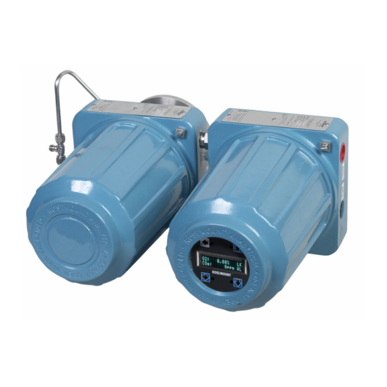
Use this complete model number for any correspondence with Emerson. Optional accessories provides a list of accessories for use with the Rosemount OCX8800. Rosemount OCX8800C... - Page 10 Figure 1-1: Typical System Package A. Quick Start Guide B. Adapter plate with mounting hardware and gasket C. Reference air and calibration set (optional) D. Blowback hardware (optional) E. Rosemount OCX8800 with remote electronics F. Rosemount OCX8800 with integral electronics Emerson.com/Rosemount...
-
Page 11: System Overview
1.2.2 System description Emerson has designed the Rosemount OCX8800 to measure oxygen and combustible concentrations in flue gas temperatures up to 2600 °F (1427 °C). Electrical connections, power, and communications are made through two ¾ national pipe thread (NPT) ports in the flameproof electronics enclosure using fittings and cables provided by the customer. - Page 12 The electronics housing may be mounted up to 150 ft. (45.7 m) from the sensor housing. The electronics control both sensor temperatures and provide output signals in one of two ways: Emerson.com/Rosemount...
- Page 13 Field Communicator: The handheld Field Communicator requires Device Description (DD) software specific to the Rosemount OCX8800. The DD software is supplied with many Field Communicators, but can also be programmed into existing Field Communicators at most Emerson service offices. Refer to Using HART communications for additional information.
- Page 14 The instrument air solenoid does not allow air flow until the heaters are up to temperature. This minimizes the amount of sampled process flue gas being pulled into the cold sensors causing condensation. Emerson.com/Rosemount...
- Page 15 O. Flow meter: 7 scfh P. Eductor air Q. Reference air R. Low O test gas S. High O test gas T. CO test gas U. Instrument air V. Flow meter: 50 cc/min. (0.1 scfh) W. Dilution air Rosemount OCX8800C...
- Page 16 185 °F (85 °C). Retain packaging in which the transmitter arrived from the factory in case any components are to be shipped to another site. This packaging haws been designed to protect the product. Emerson.com/Rosemount...
- Page 17 A. Rosemount OCX8800 with integral electronics B. Instrument air C. Three calibration lines by customer (300 ft. [91 m] maximum) D. Signal output (twisted pairs) E. Termination in control room F. Field Communicator G. Customer's laptop with AMS H. AMS Rosemount OCX8800C...
- Page 18 D. Instrument air supply (reference gas) E. High O test gas F. Low O test gas G. CO test gas H. Gases I. Duct J. Stack K. Test gas flow meter L. Dilution air flow meter M. Pressure regulator Emerson.com/Rosemount...
- Page 19 G. Dilution air flow meter H. 4-20 mA outputs (two twisted pairs) I. Line voltage J. Instrument air supply (reference gas) K. Pressure regulator L. High O test gas M. Low O test gas N. CO test gas Rosemount OCX8800C...
- Page 20 Description and specifications Manual December 2022 00809-0500-4881 Figure 1-6: Optional Sample Tube Support C. 0.75-in. (19 mm) diameter on 7.5-in. (190 mm) diameter B.C., eight places D. 0.75-in. (19 mm) diameter on 4.75-in. (121 mm) diameter B.C., four places Emerson.com/Rosemount...
- Page 21 114.5 (2907) Figure 1-7: Optional In-Situ Filters A. In-situ stainless steel or Hastelloy filter B. In-situ high surface area stainless steel filter Figure 1-8: Optional Panel Mounted Blowback and Calibration/Reference Air Set (19-in. [482.6 mm] Rack or Wall Mount) Rosemount OCX8800C...
-
Page 22: Specifications
10 seconds T90 Combustibles 25 seconds T90 1.3.5 Temperature limits Process 32 to 2600 °F (0 to 1427 °C) Sensors housing -40 to 212 °F (-40 to 100 °C) ambient Electronics housing -40 to 149 °F (-40 to 65 °C), ambient Emerson.com/Rosemount... - Page 23 9-ft (2.74 m) probe package 59 lb. (22 kg) 1.3.7 Mounting Flange 1.3.8 Materials Probes 316L stainless steel: 1300 °F (704 °C) Inconel 600: 1832 °F (1000 °C) Ceramic: 2600 °F (1427 °C) Enclosures Low copper aluminum 1.3.9 Calibration Semi-automatic or automatic Rosemount OCX8800C...
- Page 24 Electronics housing Type 4X, IP66 with fitting and pipe on reference exhaust port to clean, dry atmosphere, two ¾-14 NPT conduit ports (when reference air vents are routed to a dry area. 1.3.18 Electrical noise Meets EN 61326, Class A Emerson.com/Rosemount...
-
Page 25: Ordering Information
Alarm Alarm output relay - dry contact, form C, 30 mA, 30 Vdc capability 1.3.25 Power consumption 750 W maximum 1.4 Ordering information For ordering information, refer to the Rosemount OCX8800 Oxygen and Combustibles Transmitter Product Data Sheet. Rosemount OCX8800C... - Page 26 Description and specifications Manual December 2022 00809-0500-4881 Emerson.com/Rosemount...
-
Page 27: Chapter 2 Install
Plug all unused ports on the probe housing and enclosure with a suitable filling. 2.1 Product safety WARNING Safety instructions Failure to follow the safety instructions could result in serious injury or death. Before installing this equipment, read Essential instructions. Rosemount OCX8800C... -
Page 28: Mechanical Installation
Select the sensing point so the process gas temperature falls within the range of probe material used. CAUTION Damage to the electronics may result. Do not allow the temperature of the electronics housing to exceed 185 °F (85 °C). Emerson.com/Rosemount... - Page 29 Make the necessary repairs or install the transmitter upstream of any leakage. 2. Ensure the area is clear of internal and external obstructions that will interfere with installation and maintenance access to the transmitter. Allow adequate clearance for the removal of the transmitter. Rosemount OCX8800C...
- Page 30 2-1. D. Flange diameter E. B.C. diameter F. Hole diameter G. See Table 2-2. H. Allow 9 in. (229 mm) for cover removal. I. Bottom view J. Optional in situ filter Table 2-1: 0.06-in. Thick Gasket ANSI 353B18H02 353B45H01 Emerson.com/Rosemount...
- Page 31 4. Ensure the conduits drop vertically from the transmitter and the conduit is routed below the level of the conduit ports on the housing to form a drip loop. Drip loops minimize the possibility that moisture will damage the electronics. Rosemount OCX8800C...
- Page 32 00809-0500-4881 Figure 2-2: Installation with Drip Loops A. Duct wall B. Conduit drip loops 5. Where a positive stack pressure exists at the installation site, connect all pneumatic lines prior to installing the transmitter in the stack or ductwork. Emerson.com/Rosemount...
-
Page 33: Electrical Installation
This circuit breaker should also include a mechanically operated isolating switch. If not, then another external means of disconnecting the supply from the equipment should be located close by. Circuit breakers or switches must comply with a recognized standard such as IEC 947. Rosemount OCX8800C... - Page 34 Oxygen (O ) 4-20 mA signal One 4-20 mA signal represents the O value. Superimposed on the O signal is the F Fieldbus information accessible ™ OUNDATION through a handheld communicator or Asset Management Solutions (AMS) Device Manager software. Emerson.com/Rosemount...
- Page 35 Remote electronics connections to sensor housing Make the following connections between the remote electronics and sensor housings with the electronics cable ordered with the package (Figure 2-3). Braided cable is available in lengths up to 150 ft (46 m). Rosemount OCX8800C...
- Page 36 Figure 2-3: Electrical Connections between Remote Electronics and Sensor Housing A. To ground screw B. Heater power connector (J3) C. COe sensor and cold junction connector (J4) D. O sensor and thermocouple connector (J5) E. Heater power cable F. Electronics housing G. Sensor housing H. Signal cable Emerson.com/Rosemount...
- Page 37 Black T/C SB - Green T/C O Black T/C O Blue cell + Black cell - Note Interconnect wiring shown is for Rosemount supplied cables. For customer furnished interconnect wiring or cables, refer to Figure 2-4 Figure 2-5. Rosemount OCX8800C...
- Page 38 J. Heat shrink tubing 1 in. (25.4 mm) long, 3/16 in. (4.8 mm) size K. Typical on both ends of wiring L. 2.0 ± 0.25 typical M. For RFI/CE compliance, the connector must provide 360 degrees of electrical contact to the cable shield. Emerson.com/Rosemount...
- Page 39 2.3.9 Signal connections Connect the electronics housing terminals to the corresponding terminals in the sensor housing. The twisted wire pairs are numbered on the inner plastic wrapper. Keep twisted pairs together and match the numbers and wire colors. Rosemount OCX8800C...
-
Page 40: Pneumatic Installation
J. EMI filter K. External tooth locks washer L. Signal port ¾-in. NPT M. Power port ¾-in. NPT 2.4 Pneumatic installation Pneumatic system connections depend on whether reference air set, calibration solenoids, and/or blowback equipment options are equipped on your transmitter. Emerson.com/Rosemount... - Page 41 5. Connect the output of the test gas sources to the inlet port of the CAL GAS flow meter. Install an air line between the flow meter outlet port and the CAL GAS inlet fitting on the sensor housing. Rosemount OCX8800C...
- Page 42 Hazardous area: 45 psig (3.1 barg) M. 2-in. pressure gauge, 0 to 60 psig (0 to 4.1 barg) N. Combination filter-regulator, 0 to 60 psig (0 to 4.1 barg) O. Flow meter, 1-10 scfh P. Flow meter, 0.05-0.5 scfh Emerson.com/Rosemount...
- Page 43 5. Connect the CAL GAS outlet fitting of the electronics housing to the inlet port of the CAL GAS flow meter. Install an air line between the flow meter outlet port and the CAL GAS inlet fitting on the sensor housing. Rosemount OCX8800C...
- Page 44 L. Pressure regulator/filter 35 psig (2.4 barg) for general purpose, 45 psig (3.1 barg) for hazardous areas M. 2-in. pressure gauge 0-60 psig (0 to 4.1 barg) N. Combination filter-reg. 0-60 psig (0 to 4.1 barg) O. Flow meter 1-10 scfh P. Flow meter 0.05-0.5 scfh Q. Calibration gas out Emerson.com/Rosemount...
- Page 45 Figure 2-9 shows the piping arrangement for the transmitter with autocalibration when the COe zero function is used. The arrangement is similar to Figure 2-8, except instrument air is used as the high O test gas. Rosemount OCX8800C...
- Page 46 O. Flow meter, 1-10 scfh P. Flow meter, 0.05-0.5 scfh Q. Calibration gas out Note If instrument is to be used as the high O calibration gas, the low O and COe calibration gases must also be set to the same pressure. Emerson.com/Rosemount...
- Page 47 Figure 2-10 shows the piping arrangement for the transmitter with the blowback and autocalibration options when COe zero function is used. The arrangement is similar to Figure 2-8 except instrument air is used as the high O test gas. Rosemount OCX8800C...
- Page 48 Q. Blowback valve, air operated R. 2-in. pressure gauge, 0 to 60 psig (0 to 4.1 barg) S. Combination filter/regulator, 0 to 60 psig (0 to 4.1 barg) T. Flow meter, 1-10 scfh During blowback operation, states of both solenoid valves change. Emerson.com/Rosemount...
-
Page 49: Initial Start-Up
Upon completing installation, make sure that the transmitter is turned on and operating prior to firing up the combustion process. During outages, and whenever possible, leave the transmitter running to prevent condensation and premature aging from thermal cycling. Rosemount OCX8800C... - Page 50 Install Manual December 2022 00809-0500-4881 Emerson.com/Rosemount...
-
Page 51: Configuration And Start-Up
All switches are accessible through holes in the electronics box. CAUTION Equipment damage If defaults are changed under power, damage to the electronics may occur. Remove power from the transmitter before changing defaults. Verify that the following switch settings are correct for your installation. Rosemount OCX8800C... - Page 52 Rail limits: — Open High: 21.1 mA — Closed Low: 3.5 mA SW1: The two settings are internally or externally powering the O 4-20 mA signal. The factory setting is for the O 4-20 mA signal to be internally powered. Emerson.com/Rosemount...
- Page 53 The switch is accessible through holes in the electronics box. CAUTION Equipment damage If defaults are changed under power, damage to the electronics may occur. Remove power from the transmitter before changing defaults. Rosemount OCX8800C...
-
Page 54: Initial Power Up
Normal operating temperature for the O cell is 1357 °F (736 °C). Normal operating temperature for the combustibles cell is 572 °F (300 °C). The normal Emerson.com/Rosemount... -
Page 55: Setting Test Gas Values
LOW GAS. Enter the percent O used for the low test gas 6. From the TRANSDUCER menu, select COe CAL SETUP. 7. From COe CAL SETUP, select COe Test Gas. Enter the CO concentration (ppm) used for the COe test gas. Rosemount OCX8800C... -
Page 56: Reset
3. From the SYSTEM submenu, select the Status submenu. 4. From the Status submenu, select Reset Device. The transmitter resets, and the LOI reverts to the normal operation display. 3.4.2 Reset with Field Communicator Remove the transmitter from the process loop and recycle power. Emerson.com/Rosemount... -
Page 57: Calibration Solenoids
00809-0500-4881 December 2022 3.5 Calibration solenoids Emerson can provide the transmitter with optional calibration solenoids for autocalibration. The transmitter's software controls the solenoids, which automatically switch in the proper calibration gas during the calibration cycle. 3.5.1 Configure the calibration solenoids with the Field Communicator - HART ®... - Page 58 Blowback Period: Length of time blowback is activated (FIVE seconds recommended). • Blowback Purge Time: Length of time after blowback is complete before oxygen/combustibles readings are considered valid (set as required by the application). • Initiate Blowback: Intiates a blowback event manually. Emerson.com/Rosemount...
-
Page 59: Calibration Verify Feature
• Blow Bk Period: Length of time blowback in activated. Range is one to five seconds. Default is two seconds. Emerson recommends five seconds. • Blow Bk Purge: Length of time after blowback is complete before oxygen/combustibles readings are considered valid. Range is 0 to 500 seconds. - Page 60 A purge automatically follows a gas flow. 3.7.3 Verify calibration with the LOI Procedure 1. Use the Z pattern to enter the LOI menu tree. 2. From the CALIBRATION menu, select Cal Verify. 3. From the Cal Verify menu, select the functions as follows: Emerson.com/Rosemount...
-
Page 61: Calibration Tolerance Feature
5. Go back to the CAL SETUP menu and select COe CAL PARAMS. 6. To enable the calibration tolerance for the combustibles calibration, from the COe CAL PARAMS menu, select COe Tol Check. Select On to enable the calibration tolerance feature. Rosemount OCX8800C... -
Page 62: Coe Purge/Zero Feature
COe zero feature. Switching between the two gases must be manually coordinated between scheduled calibrations and COe zero events. When the COe zero feature is used, special pneumatic connections are required. Emerson.com/Rosemount... - Page 63 Valid choices are Yes and No. A Yes choice will cause the COe calibration constant to update. Note At the completion of the COe Zero Function, the COe analog output signal will change if the Zero Update parameter is set to Yes. Rosemount OCX8800C...
- Page 64 Default is 60 seconds. Total duration of this function is flow time plus purge time. • COe Zero Tracks: Determines if the analog output signals track or hold during the function. Valid choices are None, Both, COe, and O Emerson.com/Rosemount...
- Page 65 00809-0500-4881 December 2022 • COe Zero Update: Determines if the COe calibration constant is updated at the end of the function. Valid choices are Yes and No. A Yes choice will cause the COe calibration constant to update. Rosemount OCX8800C...
- Page 66 Configuration and start-up Manual December 2022 00809-0500-4881 Emerson.com/Rosemount...
-
Page 67: Using The Local Operator Interface (Loi)
4-1. There are four mating connectors on the back of the LOI module that allow the LOI to be oriented as desired. Figure 4-1: LOI components mounting A. Electronics housing (cover removed) B. Electronics stack C. LOI connector D. LOI board E. LOI module Rosemount OCX8800C... -
Page 68: Local Operator Interface (Loi) Controls
O signal terminates via a Field Communicator. The transmitter also uses HART ® communications, permitting access to all instrument functionality anywhere the 4-20 mA signal terminates via a HART Field Communicator. Emerson.com/Rosemount... - Page 69 Enter key, used after the digits of a parameter value are entered and the cursor is moved to its left-most position. When you touch the Enter key, the new parameter value, if accepted, will appear in the top line of the display. Rosemount OCX8800C...
- Page 70 CAUTION Excessive dust can prevent the LOI from entering lockout. This condition can cause uncommanded operations to occur. Always clean dust and soil away from the LOI screen each time the LOI is used. Figure 4-3: Z Pattern Entry Emerson.com/Rosemount...
-
Page 71: Local Operator Interface (Loi) Menu Tree
(after warm-up). Sensors are warming up to operating temperaturs. Warm-Up: The transmitter's heaters are ramping up to operating temperature. 4.3 Local operator interface (LOI) menu tree Figure 4-4 displays the LOI menu tree that is specific to the Rosemount OCX8800. Rosemount OCX8800C... - Page 72 Using the local operator interface (LOI) Manual December 2022 00809-0500-4881 Figure 4-4: LOI Menu Tree Emerson.com/Rosemount...
- Page 73 Manual Using the local operator interface (LOI) 00809-0500-4881 December 2022 Rosemount OCX8800C...
- Page 74 Using the local operator interface (LOI) Manual December 2022 00809-0500-4881 Emerson.com/Rosemount...
- Page 75 From the first column submenus, press Right to move the display into the second column submenus. Press Up and Down to move the display to the second column submenus of the first column submenu selected. Press Left to move the display back to the first column submenu. Rosemount OCX8800C...
-
Page 76: D/A Trim Procedures
Up and Down to change the value. When the correct value is displayed, use Enter to input the value. The LOI displays a 20 mA...Meter. The trim program inputs the design- equivalent signal for a 20.00 mA output. Emerson.com/Rosemount... - Page 77 Connect the positive lead to the AOUT2+ terminal and connect the negative lead to the AOUT2- terminal. Then press Enter on the LOI. The LOI displays 4 mA...Meter. The trim program inputs the design equivalent signal for a 4.00 mA output. Rosemount OCX8800C...
- Page 78 Then use Enter to input the response. If no, the process repeats from Step When the responses in Step 8 Step 9are yes, the trim procedure is complete. Postrequisites Exit the LOI menu and return the control loop to automatic control. Emerson.com/Rosemount...
-
Page 79: Using Hart ® Communications
For applications in which the signal line has a load resistance of 250 ohms or more, refer to Method 1: For load resistance ≥ 250 ohms. For applications in which the signal line load is less than 250 ohms, refer to Method 2: For load resistance < ohms. Rosemount OCX8800C... - Page 80 1. Using the supplied lead set, connect the Field Communicator in parallel to the transmitter. 2. Use any wiring termination points in the analog output 4-20 mA signal line. 3. You can also connect the Field Communicator directly to the transmitter electronics board. Emerson.com/Rosemount...
-
Page 81: Field Communicator Pc Connections
When powering up a disconnected (off-line) Field Communicator, the LCD displays the Main Menu. When powering up a connected (on-line) Field Communicator, the LCD displays the On-line Menu. Refer to the Field Communicator manual for detailed menu information. Rosemount OCX8800C... -
Page 82: Hart ® Menu Tree
Using HART communications Manual ® December 2022 00809-0500-4881 5.4 HART menu tree ® Figure 5-2 provides a menu tree for the Field Communicator, which is specific to Rosemount OCX8800 applications. Figure 5-2: HART Menu Tree Emerson.com/Rosemount... - Page 83 Manual Using HART communications ® 00809-0500-4881 December 2022 Rosemount OCX8800C...
- Page 84 Using HART communications Manual ® December 2022 00809-0500-4881 Emerson.com/Rosemount...
- Page 85 Manual Using HART communications ® 00809-0500-4881 December 2022 Rosemount OCX8800C...
-
Page 86: D/A Trim Procedures
The Field Communicator displays Fld dev output 4.00 mA equal to reference meter? 9. Using Up or Down, select 1 Yes or 2 No and press ENTER. If No, the process repeats from Step The Field Communicator displays Setting Fld dev output to 20 mA. 10. Press OK. Emerson.com/Rosemount... - Page 87 The Field Communicator displays Setting Fld dev output to 4 mA. 9. Press OK. The Field Communicator displays Fld dev output 4.00 mA equal to reference meter? 10. Using Up or Down, select 1 Yes or 2 No. Press ENTER. Rosemount OCX8800C...
- Page 88 The Field Communicator displays Fld output 20.00 mA equal to reference meter? 12. Using Up or Down, select 1 Yes or 2 No. Press ENTER. If No, the process repeats from Step The Field Communicator displays NOTE: Loop may be returned to automatic control. Emerson.com/Rosemount...
-
Page 89: Chapter 6 Calibration
4. Scroll down to the last item, Use Solenoids. If the transmitter is equipped with calibration solenoids and you want timed automatic calibration, select Yes. 5. Press Up to select O2 Out Tracks. Select Yes or No to determine if the transmitter will update the O lock value. Rosemount OCX8800C... - Page 90 6. At the prompt, input a time interval (in hours) at which an automatic O calibration will occur and press ENTER. 7. From the DETAILED SETUP screen, select COE CALIB PARAMS. 8. From the COE CALIB PARAMS menu, select CalIntrvl. Emerson.com/Rosemount...
-
Page 91: Operator-Initiated Autocalibration
If necessary, refer to Figure 4-4. Once the the operator initiates the manual calibration procedure at the LOI, a series of prompts will appear giving instructions to the operator. Procedure 1. Press Right to select the CALIBRATION first column submenu. Rosemount OCX8800C... - Page 92 To return to a preceding menu, press Left. Procedure 1. From the DEVICE SETUP menu, select DIAG/SERVICE. 2. From the DIAG/SERVICE menu, select CALIBRATION. 3. From the CALIBRATION menu, select CAL CONTROL. 4. From the CAL CONTROL menu, select CAL METHODS. Emerson.com/Rosemount...
- Page 93 ReadO2Hi for a period of time. During this period, if you try to go the next calibration step by pressing OK and selecting START/NEXT CALSTEP, you will be prompted with Operator step command is not accepted at this Rosemount OCX8800C...
- Page 94 • ABORT/CANCEL to Exit 8. From the SELECT ACTION screen, select START CAL/STEP CAL to continue calibration, select ABORT CAL to abort calibration, or select EXIT CAL to exit calibration. Select one item from the list and press ENTER. Emerson.com/Rosemount...
- Page 95 Mode (OOS). 2. To set the OOS mode, select Transducer; then select Process, followed by Out of Service on the Target Mode screen. 3. From the Transducer screen, select Methods. 4. From the Methods screen, select OCX Calibration. Rosemount OCX8800C...
- Page 96 Calibration Step will stop at the Apply O High Gas/ Apply Comb High Gas. 11. Switch off the O low gas/sample reference air and switch on the O high gas/combustibles test gas. Verify the O /COe concentration measured Emerson.com/Rosemount...
- Page 97 When the Purge step is complete, the Calibration Step will be at Idle . The alarm will be set if the calibration has failed. Calibration Failed 17. When calibration is complete, select Exit to exit the calibration method. Rosemount OCX8800C...
- Page 98 Calibration Manual December 2022 00809-0500-4881 Emerson.com/Rosemount...
-
Page 99: Chapter 7 Field Communicator
A minimum 250 ohms resistance must be present in the HART loop for the Field Communicator to function properly. WARNING EXPLOSION Explosions can result in death or serious injury. Do not make connections to the Field Communicator's serial port, digital signal line, or NiCad recharger jack in an explosive atmosphere. Rosemount OCX8800C... - Page 100 WARNING EXPLOSION Explosions can result in death or serious injury. Do not make connections to the Field Communicator's serial port, digital signal line, or NiCad recharger jack in an explosive atmosphere. Emerson.com/Rosemount...
- Page 101 A. Terminal connectors B. Terminal block C. Terminals D. Field Communicator E. Lead set F. Fieldbus signal G. Fieldbus digital signal H. Fieldbus computer terminal (PC) I. Field Communicator rear panel Note Devices shown are not to scale. Rosemount OCX8800C...
-
Page 102: Fieldbus Menu Tree
Field Communicator Manual December 2022 00809-0500-4881 7.3 Fieldbus menu tree Figure 7-3 displays menu for the Field Communicator using the Fieldbus protocol. This menu is specific to the Hazardous Area Rosemount OCX8800 applications. Emerson.com/Rosemount... - Page 103 Manual Field Communicator 00809-0500-4881 December 2022 Refer to the Fieldbus parameter descriptions for the applicable range, units, and description for the Fieldbus menu parameters. Figure 7-3: Fieldbus Menu Tree Rosemount OCX8800C...
- Page 104 Field Communicator Manual December 2022 00809-0500-4881 Emerson.com/Rosemount...
- Page 105 Manual Field Communicator 00809-0500-4881 December 2022 Rosemount OCX8800C...
- Page 106 Field Communicator Manual December 2022 00809-0500-4881 Emerson.com/Rosemount...
-
Page 107: Chapter 8 Foundation ™ Fieldbus
Fieldbus an enabling technology. OUNDATION Emerson offers a full range of products from field devices to the DeltaV scalable control system to allow an easy transition to Fieldbus technology. The Fieldbus retains the features of the 4-20 mA analog system, including... - Page 108 The input snap process ensures that these values do not change during the block execution. New values received for these parameters do not affect the snapped values and will not be used by the function block during the current execution. Emerson.com/Rosemount...
- Page 109 System management services locate a block by its tag. Thus, the service personnel need only know the tag of the block to access or change the appropriate block parameters. Function blocks are also capable of performing short-term data collection and storage for reviewing their behavior. Rosemount OCX8800C...
- Page 110 In addition to function blocks, Fieldbus contains two other block types to support the function blocks. These are the resource block and the transducer block. The resource block contains the hardware specific characteristics associated with a device. Transducer blocks couple the function blocks to local input/output functions. Emerson.com/Rosemount...
-
Page 111: Network Communication
Alarms not only report a status change when a block leaves a particular state, but also report when it returns back to that state. 8.2 Network communication Figure 8-2 illustrates a simple Fieldbus network consisting of a single segment (link). Rosemount OCX8800C... - Page 112 LAS. Only the device with the token can communicate. The LAS maintains a list of all devices that need access to the bus. This list is called the Live List. Emerson.com/Rosemount...
-
Page 113: Rosemount Ocx8800 Function Blocks
Addresses 0 through 15 are reserved for group addressing and for use by the data link layer. For all Emerson Fieldbus devices, addresses 20 through 35 are available to the device. If there are two or more devices with the same address, the first device to start uses its programmed address. -
Page 114: Resource Block
The PWA alarms can be Suppressed to mask out failures from annunciation. Sensor Malfunction The Sensor Alerts tab displays one of the following alerts: • Cell Open • Comb Cell Error This alert is active when the sensor is indicating a very high or unexpected output. Emerson.com/Rosemount... - Page 115 T/C Shorted 3. O T/C Reversed 4. Comb T/C Open 5. Comb T/C Shorted 6. Comb T/C Reversed 7. S/B T/C Open 8. S/B T/C Shorted 9. S/B T/C Reversed This alert indicates a miswired or faulty thermocouple. Rosemount OCX8800C...
- Page 116 Diagnose at the transmitter. Refer to Diagnostic alarms for details. Recommended actions 1. Check heater circuit for loose or broken connections. 2. Check thermocouple wiring. 3. Test or replace the heater. Emerson.com/Rosemount...
- Page 117 3. There are fluctuations or noise in the power supplied to the transmitter. Recommended actions 1. Allow the transmitter several minutes to reach proper temperature. 2. Check power supply. Calibration Error The Calibration Alerts tab may display the following alarms: Rosemount OCX8800C...
- Page 118 4. ROM Integrity Error The non-volatile parameter storage on the CPU board has become unreliable. Potential cause This alarm generally occurs during start-up. Rarely, the transmitter could be powered down while a parameter is being stored to the non-volatile memory. The Emerson.com/Rosemount...
- Page 119 2. ADC Reference Error This alert indicates faulty operation of the device electronics. Potential cuase The transmitter continually monitors the analog to digital converter (ADC) for correc operation. Refer to Diagnostic alarms for details. Recommended actions 1. Cycle power. Rosemount OCX8800C...
- Page 120 This alert may display on the FF/Device Alerts AMS tab. This alert occurs when the PWA simulate mode is active. You can now write the PWA active parameters. You can also write the resource block detailed status parameters and the internal alerts in the transducer block where the PWA active alarms originate. Emerson.com/Rosemount...
- Page 121 3. Select Enable to enable the simulation feature or Disable to disable the simulation feature. 4. Once the method is complete, select the Simulate PWA tab in the resource block, Figure 8-3. If the simulation is enabled, the PlantWeb Alarm Simulate parameter is configurable; otherwise it is read-only. Rosemount OCX8800C...
-
Page 122: Configure Plantweb Alert (Pwa) Simulation With The Field Communicator
8.5 Configure PlantWeb alert (PWA) simulation with the Field Communicator Use the following procedure to configure PWA simulation using the Field Communicator. Procedure 1. Run the Transmitter Options method in the resource block (Resource → Methods) Emerson.com/Rosemount... - Page 123 Input Failure: Set whenever there is a communication error between the Fieldbus card and the transmitter. • Simulation Active: Set whenever the Fieldbus Simulate switch is set to On at the Fieldbus card or the Software simulate option is enabled. • Other error: Set whenever XD_ERROR is non-zero. Rosemount OCX8800C...
-
Page 124: Transducer Block
See FF-891, Section 5.3. BLOCK_ERR See FF-891, Section 5.3. BLOWBACK_DURATION Seconds The amount of time the blowback solenoid will be on. BLOWBACK_ENABLED 0: No Enumerated Enables or disables the 1: Yes automatic blowback cycle. BLOWBACK_INTERVAL 0-32767 Minutes The time between blowback cycles. Emerson.com/Rosemount... - Page 125 See FF-903, Sections 3.3 and 4.5. COMB_SENSOR_CAL_WHO See FF-903, Section 3.3. COMB_AUTOCAL_INTERVAL 0-9999 Hours The time between automatic calibrations of the combustibles sensor. COMB_CAL_POINT 0-55000 The value of the combustibles test gas. COMB_CONSTANT -99.0 to 99.0 The combustibles calibration constant. Rosemount OCX8800C...
- Page 126 The high and low range RANGE limit values, the engineering units code, and the number of digits to the right of the decimal point for the combustibles reading. COMB_PRIMARY_VALUE_TY See FF-903, Section 3.3 COMB_REFERENCE_OHMS Ohms The raw value of the combustibles reference input. Emerson.com/Rosemount...
- Page 127 Combustible block INPUT thermocouple (T/C) voltage (valid only with Type 3 sensor). COMB_TIME_TO_NEXT 0 - 9999 Hours The time until the next automatic calibration of the combustibles sensor. COMB_TOL_CHECK 0: No Combustible calibration 1: Yes gas tolerance check. Rosemount OCX8800C...
- Page 128 0 - 16777215 Bit Enum A bit-enumerated value used to communicate the status of the transmitter. (This is similar to the command 48 status bits in HART). ELECTRONICS_TEMP ° C The current temperature reading of the electronics temperature sensor. Emerson.com/Rosemount...
- Page 129 O calculation. O2_HTR_DUTYCYCLE heater duty cycle. O2_IMPEDANCE_CAL Ohms The impedance value that was calculated as a result of the current successful O calibration. O2_PERCENT_OF_RANGE The percent of range of the current O reading. Rosemount OCX8800C...
- Page 130 34.5-47.5 mV/Decade The O calibration slope. O2_T90 0-300 Seconds The amount of time that the O process variable will take to reach 90% of the actual process variable. O2_TEMP_MAX ° C The highest O temperature read since power on. Emerson.com/Rosemount...
- Page 131 SENSOR_HOUSING_TYPE 0, 1, 2, 3 Enumerated This is the sensor housing type setting through the DIP switch. (0 = Type 1, 1 = Type 2, 2 = Type 3, 3 = Invalid) Rosemount OCX8800C...
- Page 132 Start flow high O , 1 = Start flow lo O , 2 = Start flow high COe, 3 = Purge gas, 6 = No effect) VERIFY_STATE_TIME Seconds Time remaining for the current calibration check state. XD_ERROR See FF-903, Section 3.3. Emerson.com/Rosemount...
-
Page 133: Transducer Block Enumerations
Read combistibles low gas Apply combustibles high gas Yes, if parameter Solenoids Present is 0.. Flow combustibles high gas Read combustibles high gas Stop gas Yes, if parameter Solenoids Present is 0. Purge Abort Yes, if parameter Solenoids Present is 0. Rosemount OCX8800C... - Page 134 BLOWBACK_STATE description Idle Blow Purge Table 8-7: Alarm Event Enumerations ALARM_RELAY_EVENT description In calibration cell temp error heater open cell bad Cal failed Cal warn High electronics temp Unit failure SL temp error Comb cell temp error Power input error Emerson.com/Rosemount...
- Page 135 CO slope error CO constant error CO tolerance check failed CO slope warning During a running calibration verify procedure, the states below reflect the current step that the calibration verify is running in. Rosemount OCX8800C...
- Page 136 COZERO_STATE description Idle Flowing Purging Table 8-14: COe out Tracks Enumerations COZERO_OUTTRAK description None Both Table 8-15: Detailed Status Alarm number Description Value of XD_ERROr (see FF-903) No alarm active cell open Mechanical failure cell impedance high Mechanical failure Emerson.com/Rosemount...
- Page 137 Calibration error Combustibles calibration failed Calibration error Combustibles calibration warning Calibration error calibration recommended Calibration error EEPROM corrupt Data integrity error High electronics temperature Electronics failure ADC timeout error Electronics failure ADC reference error Electronics failure Rosemount OCX8800C...
- Page 138 1000 ° C 8.7.4 Transducer block channel status The status of channels 1 through 4 are affected by the state of the unit alarm. In all cases, the channel reads what it believes are the correct sensor values. Self- Emerson.com/Rosemount...
- Page 139 3, 4 Calibrating, Cal GOOD NON_SPECIFIC NOT_LIMITED verify, Blowback 3, 4 Alarm, System fault DEVICE_FAILURE CONSTANT (Temperature related alarms: thermocouple (T/C) open, T/C shorted, T/C reversed, ADC error) 3, 4 Temp low & high GOOD ACTIVE_BLOCK_ NOT_LIMITED ALARM Rosemount OCX8800C...
-
Page 140: Analog Input (Ai) Function Block
AI block is in engineering units and contains a status indicating the quality of the measurment. The measuring device may have several measurements or derived values available in different channels. Use the channel number to define the variable that the AI block processes. Emerson.com/Rosemount... - Page 141 Table 8-19: Definitions of AI Function Block System Parameters Parameter Index number Units Description ACK_OPTION None Used to set auto acknowledgement of alarms. ALARM_HYS Percent The amount the alarm value must return within the alarm limit before the associated active alarm condition clears. Rosemount OCX8800C...
- Page 142 Active status if the subcode has changed. BLOCK_ERR None This parameter reflects the error status associated with the hardware or software components associated with a block. It is a bit string, so that multiple errors may be shown. Emerson.com/Rosemount...
- Page 143 HI HI alarm condition. HI_HI_PRI None The priority of the HI HI alarm. HI_LIM EU of PV_SCALE The setting for the alarm limit used to detect the HI alarm condition. HI_PRI None The priority of the HI alarm. Rosemount OCX8800C...
- Page 144 LO LO alarm condition. LO_LO_PRI None The priority of the LO LO alarm. LO_PRI None The priority of the LO alarm. LOW_CUT If percentage value of transducer input fails below this, PV = 0. Emerson.com/Rosemount...
- Page 145 STRATEGY None You can use the STRATEGY field to identify grouping of blocks. This data is not checked or processed by the block. Rosemount OCX8800C...
- Page 146 With simulation enabled, the actual measurement value has no impact on the OUT value or the status. Emerson.com/Rosemount...
- Page 147 E. PV_Ftime F. IO_opts G. Field_val H. Out_scale XD_scale I. Channel J. Low_cut K. Alarm_hys L. Hi_Hi_Lim Hi_Lim Lo_Lo_Lim Lo_Lim M. Access analog measurement N. Alarm detection O. Simulate P. Convert Q. Cutoff R. Filter S. Status calculation Rosemount OCX8800C...
- Page 148 The filtering feature changes transmitter's response time to smooth variations in input readings caused by rapid changes in input. You can adjust the filter time constant (in seconds) using the PV_FTIME parameter. Set the filter time constant to zero to disable the filter feature. Emerson.com/Rosemount...
- Page 149 (PV). This option is useful to eliminate false readings when the differential pressure measurement is close to zero, and it may also be useful with zero-based measurement devices such as flow meters. Rosemount OCX8800C...
- Page 150 Out of service (O/S): The block is not processed. FIELD_VAL and PV are not updated, and the OUT status is set to Bad: Out of Service. The BLOCK_ERR parameter shows Out of Service. In this mode, you can make changes to all Emerson.com/Rosemount...
- Page 151 Normally, the status of the PV reflects the status of the measurement value, the operating condition of the I/O card, and any active alarm condition. In Auto mode, OUT reflects the value and status quality of the PV. In Man mode, the OUT status Rosemount OCX8800C...
- Page 152 VAR_INDEX: Process variability index measured as the integral of average absolute error between PV and its mean value over the previous evaluation period. this index is calculated as a percent of OUT span and is updated at the end of the time period defined by VAR_SCAN. Emerson.com/Rosemount...
- Page 153 Table 8-21 lists the appropriate configuration settings, and Figure 8-7 illustrates the correct function block configuration. Table 8-21: Analog Input Function Block Configuration for a Typical Temperature Transmitter Parameter Configured values L_TYPE Direct XD_SCALE Not used OUT_SCALE Not used Rosemount OCX8800C...
- Page 154 The level measurement will be used to control the level of liquid in the tank. The maximum level at the tankis 16 ft. (4.9 m) The liquid in the tank has a density that makes the level correspond to a pressure of 7.0 psi (0.5 BarG) at the pressure tap (Figure 8-8). Emerson.com/Rosemount...
- Page 155 Table 8-22: Analog Input Function Diagram for a Pressure Transmitter Used in Level Measurement (Situation #1) Parameter Configured values L_TYPE Indirect XD_SCALE 0 to 7 psi (0 to 0.5 BarG) OUT_SCALE 0 to 16 ft (0 to 4.9 m) Rosemount OCX8800C...
- Page 156 D. Analog output function block Situation #2 The transmitter in situation #1 is installed below the tank in a position where the liquid column in the impulse line, when the tank is empty, is equivalent to 2.0 psi (0.1 BarG) (Figure 8-10). Emerson.com/Rosemount...
- Page 157 Differential pressure transmitter to measure flow Situation The liquid flow in a line is to be measured using the differential pressure across an orifice plate in the line, and the flow measurement will be used in a flow Rosemount OCX8800C...
- Page 158 BLOCK_ERR shows the configuration error bit set. Set the following parameters: a) Set CHANNEL to a valid value; do not leave it at the initial value of 0 . b) Set XD_SCALE.UNITS_INDX to match the units in the transducer block channel value. Emerson.com/Rosemount...
- Page 159 Clear the Propogate Fault Forward bit. Value of output does not make sense Potential cause Linearization type. Recommended action Set L_TYPE to Direct, Indirect, or Indirect Square Root; do not leave it at the initial value of 0 . Rosemount OCX8800C...
-
Page 160: Proportional/Integral/Derivative (Pid) Function Block
Limit values are outside the OUT_SCALE.EU0 and OUT_SCALE.EU100 values. Recommended action Change OUT_SCALE or set values within range. 8.9 Proportional/integral/derivative (PID) function block The PID function block combines all of the necessary logic to perform proportional/integral/derivative (PID) control. The block supports mode control, Emerson.com/Rosemount... - Page 161 OUT = The block output and status. The block supports two forms of the PID equation: Standard and Series. You can choose the appropriate equation using the FORM parameter. The standard ISA PID equation is the default selection. Rosemount OCX8800C...
- Page 162 Table 8-25: PID Function Block System Parameters Parameter Index number Units Descriptions ACK_OPTION None Used to set auto acknowledgement of alarms. ALARM_HYS Percent The amount the alarm value must return to within the alarm limit before the associated active alarm condition clears. Emerson.com/Rosemount...
- Page 163 BKCAL_IN EU of OUT_SCALE The analog input value and status from another block's BKCAL_OUT output that is used for backward output tracking for bumpless transfer and to pass limit status. Rosemount OCX8800C...
- Page 164 Allows you to specify control strategy options. The supported control options for the PID block are Track enable, Track in Manual, SP-PV Track In Man, SP-PV Track In LO or IMAN, Use PV for BCKAL OUT, and Direct Acting. Emerson.com/Rosemount...
- Page 165 FF_SCALE None The high and low scale values, engineering units code, and number of digits to the right of the decimal point associated with the feedforward value (FF_VAL). GAIN None The proportional gain value. This value cannot equal Rosemount OCX8800C...
- Page 166 The LO LO alarm data, which includes a value of the alarm, a timestamp of occurrence, and the state of the alarm. LO_LO_LIM EU of PV_SCALE The setting for the alarm limit used to detect the LO LO alarm condition. Emerson.com/Rosemount...
- Page 167 OUT. EU of PV_SCALE The process variable used in block execution. RATE Seconds The derivative action time constant. RCAS_IN EU of PV_SCALE Target setpoint and status that is provided by a supervisory host. Use when mode is RCAS. Rosemount OCX8800C...
- Page 168 The highest SP value allowed. SP_LO_LIM EU of PV_SCALE The lowest SP value allowed. SP_RATE_DN EU of PV_SCALE per Ramp rate for downward second SP changes. When the ramp rate is set to zero, the SP is used immediately. Emerson.com/Rosemount...
- Page 169 (TRK_VAL). TRK_VAL EU of TRK SCALE The value (after scaling from TRK_SCALE to OUT_SCALE) applied to OUT in LO mode. Rosemount OCX8800C...
- Page 170 2.0 degree of freedom PID. UGAMMA Percent Used to set disturbance rejection vs. tracking response action for a 2.0 degree of freedom PID. UPDATE_EVT None This alert is generated by any changes to the static data. Emerson.com/Rosemount...
- Page 171 Figure 8-14: PID function block schematic A. Feedforward calculation B. Mode C. Setpoint limiting and filtering D. PID equation E. Output limiting F. Gain rate reset G. Scaling and filtering H. Alarm detection I. Operator output J. Convert K. In L. Out Rosemount OCX8800C...
- Page 172 Set the filter time constant to zero to disable the filter feature. Feedforward calculation The feedforward value (FF_VAL) is scaled (FF_SCALE) to a common range for compatibility with the output scale (OUT_SCALE). A gain value (FF_GAIN) is applied to achieve the total feedforward contribution. Emerson.com/Rosemount...
- Page 173 PV for BKCAL_OUT option is not selected, the working setpoint (SP_WRK) is used for BKCAL_OUT. You can set control options in Manual or Out of Service mode only. When the mode is set to Auto, the SP will remain at the last value (it will no longer follow the PV). Rosemount OCX8800C...
- Page 174 The PID function block provides a modified version of feedback reset limiting that prevents windup when output or input limits are encountered and provides the proper behavior in selector applications. 8.9.5 Block errors Table 8-26 lists conditions reported in the BLOCK_ERR parameter. Emerson.com/Rosemount...
- Page 175 Local Override (LO): The track function is active. OUT is set by TRK_VAL. The BLOCK_ERR parameter shows Out of service. • Initialization Manual (IMan): The output path is not complete (for example, the cascade-to-slave path might not be open). In IMan mode, OUT tracks BKCAL_IN. Rosemount OCX8800C...
- Page 176 Alarm conditions of priority 8 to 15 are critical alarms of increasing priority. 8.9.8 Status handling Normally, the status of the PV reflects the status of the measurement value, the operating condition of the I/O card, and any active alarm condition. In Auto mode, Emerson.com/Rosemount...
- Page 177 The integral term RESET applies a correction based on the magnitude and duration of the error. Set the RESET parameter to zero for integral only control. To reduce reset action, configure the RESET parameter to be a large value. Rosemount OCX8800C...
- Page 178 A PID block is used with an analog input (AI) block and an analog output (AO) block to control the flow steam used to heat a process fluid in a heat exchanger. Figure 8-17 illustrates the process instrumentation diagram. Emerson.com/Rosemount...
- Page 179 Figure 8-18 illustrates the correct function block configuration. Figure 8-18: PID Function Block for Steam Heater Control Example A. Outlet temperature input B. AI function block C. PID function block D. AO function block E. Out F. In Rosemount OCX8800C...
- Page 180 (FF_ENABLE), the feedforward value is scaled (FF_SCALE), and a gain (FF_GAIN) is determined. Figure 8-19 illustrates the process instrumentation diagram, and Figure 8-20 illustrates the correct function block configuration. Figure 8-19: PID Function Block Feedforward Example A. Steam supply B. Steam heater C. Condensate Emerson.com/Rosemount...
- Page 181 The temperature variation will later be sensed by TT101. The temperature controller modifies the valve position to compensate for the steam pressure change. The process is slow and causes variations in the product temperature. Figure 8-21 illustrates the process instrumentation diagram. Rosemount OCX8800C...
- Page 182 The BKCAL_IN and BKCAL_OUT connections on the PID blocks are used to prevent controller windup on the master loop when the slave loop is in Manual or Automatic mode or it has reached an output constraint. Figure 8-22 illustrates the correct function block configuration. Emerson.com/Rosemount...
- Page 183 If the instrument connected to the AI block fails, you can place the AI block in Manual mode and set the output to some nominal value for use in the Integrator function block. In this case, IN at the slave PID block is constant and prevents the integral term from increasing or decreasing. Rosemount OCX8800C...
- Page 184 Refer to Table 8-27 to troubleshoot any problems that you may encounter. Table 8-27: Troubleshooting Symptom Possible causes Corrective action Mode will not leave OOS. 1. Target mode not set. 1. Set target mode to something other than OOS. Emerson.com/Rosemount...
- Page 185 Quality of or a Status of . See the Not Invited appropriate upstream block diagnostics for corrective action. Mode will not change to CAS. 1. Target mode not set. 1. Set target mode to something other than OOS. Rosemount OCX8800C...
- Page 186 Mode will not leave out of service (OOS) Mode will not leave out of service (OOS). Mode will not leave IMAN Potential cause The link is not configured; the status shows Not connected. Recommended action Configure the BKCAL_IN link to the downstream block. Emerson.com/Rosemount...
- Page 187 Recommended action Configure the CAS_IN link to the block. Potential cause The upstream block is sending back a Quality of Bad or a Status of Not Invited. Recommended action See the appropriate upstream block diagnostics for corrective action. Rosemount OCX8800C...
-
Page 188: Arithmetic (Arthm) Function Block
The arithmetic function block provides the ability to configure a range extension function for a primary input and applies the nine different arithmetic types as compensation to or augmentation of the range extended input. All operations are selected by parameter and input connection. Figure 8-24: Arithmetic (ARTHM) Function Block Emerson.com/Rosemount... - Page 189 Bad status Output failure Readback failed Out of , and . Each function block service Other reports none or a subset of these error conditions. COMP_HI_LIM EU of PV Determines the high limit of the compensation input. Rosemount OCX8800C...
- Page 190 Percent or EU of IN number of outputs is an extensible parameter in some blocks. OUT_HI_LIM EU of OUT_SCALE The maximum output value allowed. supplied by IN OUT_LO_LIM EU of OUT_RANGE The minimum output value allowed. or Supplied by IN Emerson.com/Rosemount...
- Page 191 TAG_DESC None The user description of the intended application of the block. UPDATE_EVT None This alert is generated by any changes to the static data. Rosemount OCX8800C...
- Page 192 Condition name and description number Other Block Configuration Error: The BY_PASS parameter is not configured and is set to 0, the SP_HI_LIM is less than the SP_LO_LIM, or the OUT_HI_LIM is less than the OUT_LO_LIM. Link Configuration Error Simulate Active Emerson.com/Rosemount...
- Page 193 Alarms are grouped into five levels of priority: Priority Priority description number The priority of an alarm condition changes to after the condition that caused the alarm is corrected. Rosemount OCX8800C...
- Page 194 When IN_(k) is usable: t(k) = GAIN_IN(k) * (BIAS_IN(k) + IN_(k)) • When IN_(k) is not usable, then t(k) gets the value of the last t(k) computed with a usable input. Status handling • IN_x Use Bad • IN_x Use Uncertain • IN_LO Use Uncertain • IN Use Uncertain Emerson.com/Rosemount...
- Page 195 Figure 8-26 shows the relative temperature effects on a level signal. Figure 8-26: Relative Temperature Effects on Level A. Elevated temperature level B. Indicated level calibrated at ambient temperature C. Level percent D. Milliamp signal Rosemount OCX8800C...
- Page 196 E. In_1 F. In_2 G. Arithmetic block H. Out I. Arithmetic type = flow comp-linear This application can be applied to very large storage tanks whose contents are subject to thermal expansion and contraction during seasonal changes in temperature. Emerson.com/Rosemount...
-
Page 197: Advanced Topics
8.11.2 Troubleshoot 8.12 Input selector (ISEL) function block The input selector (ISEL) function block can be used to select the first good, hot backup, maximum, minimum, or average of as many as four input values and Rosemount OCX8800C... - Page 198 SELECTED = The selected channel number. • OUT = The block output and status. Figure 8-28 illustrates the internal components of the ISEL block. Table 8-30 lists the ISEL block parameters and their descriptions, units of measure, and index numbers. Emerson.com/Rosemount...
- Page 199 One of the inputs to be selected from. IN_3 Determined by The connection input from another block. source One of the inputs to be selected from. IN_4 Determined by The connection input from another block. source One of the inputs to be selected from. Rosemount OCX8800C...
- Page 200 TAG_DESC None The user description of the intended application of the block. UPDATE_EVT None This alert is generated by any change to the static data. Emerson.com/Rosemount...
- Page 201 Input Failure/Process Variable has Bad Status: One of the inputs is bad or not connected. Output Failure: The output has the quality of Bad. Memory Failure: A memory failure has occured in FLASH, RAM or EEROM memory. Lost Static Data Lost NV Data Readback Check Failed Rosemount OCX8800C...
- Page 202 (such as diagnostics and system alerts). Alarm conditions of priority through are advisory alarms of increasing priority. 8-15 Alarm conditions of priority are critical alarms of increasing priority. Emerson.com/Rosemount...
- Page 203 The input selector (ISEL) function block can be used to select the maximum temperature input from four inputs and send it to a proportional/integral/ derivative (PID) function block to control a process water chiller (Figure 8-30) or it Rosemount OCX8800C...
- Page 204 Figure 8-30: Input Selector Function Block Application Example (SEL_TYPE = max) A. Input selector (ISEL) function block B. To another function block Figure 8-31: Input Selector Function Block Application Example (SEL_TYPE = avg) A. Input selector (ISEL) function block B. To another function block Emerson.com/Rosemount...
-
Page 205: Operation With Emerson Deltav
Good Good Good Good 8.12.7 Troubleshoot 8.13 Operation with Emerson DeltaV ™ 8.13.1 Install a new device onto a DeltaV system ™ AMS and DeltaV software allows you to manage your instrumentation and to perform on-line configurations of your instruments. - Page 206 *.ffo, *fhx, and *.reg files. The files are probably on a floppy disk or a CD- ROM that accompanies your device. On CD-ROMs delivered together with Emerson transmitters the files are located in the directory /Fieldbus. Dependent on the existing system, use the files of the appropriate subdirectory.
-
Page 207: Chapter 9 Troubleshoot
9.1.2 Electrical noise Emerson has designed the analyzer to operate in the type of environment normally found in a boiler room or control room. Noise suppression circuits are employed on all field terminations and main inputs. - Page 208 In the event that the transmitter will not power up at all, check the incoming power supply to make sure power is being delivered to the transmitter. If the incoming power supply is good, then check fuses F1 and F6 in the electronics housing. Refer to Figure 9-1 for fuse locations. Emerson.com/Rosemount...
- Page 209 Figure 9-1: Fuse Locations A. F6 Neutral (N) 10 Amp, 250 Vac B. F1 Line (L1) 10 Amp, 250 Vac C. F3 and COe heater 4 Amp, 250 Vac D. F4 Sample block heater 8 Amp, 250 Vac Rosemount OCX8800C...
-
Page 210: Diagnostic Alarms
The potential causes are listed in order of most probable to least probable. Starting with the most probable cause, inspect and test the transmitter to isolate the actual cause; then use the recommended corrective action listed to correct the problem. Emerson.com/Rosemount... - Page 211 Figure 9-2: Electrical Connections between Electronics and Sensor Housing A. To ground screw B. Heater power connector (J3) C. COe sensor and cold junction connector (J4) D. O sensor and thermocouple connector (J5) E. Heater power cable F. Electronics housing G. Sensor housing H. Signal cable Rosemount OCX8800C...
- Page 212 Cold junction connector (CJC)+ Black CJC- Black Execute- Table 9-3: J5 Connections Wire color Connects to Thermocouple (T/C) CO+ Black T/C CO- White T/C sample block (SB)+ Black T/C SB- Green T/C O Black T/C O Blue cell+ Black cell- Emerson.com/Rosemount...
- Page 213 Troubleshoot 00809-0500-4881 December 2022 Figure 9-3: Oxygen and Cell Output A. Oxygen concentration (percentage) B. Transmitter output (millivolt) 9.3.1 O2 Sensor R High or O2 Sensor Open Oxygen sensor resistance high, > 5000 ohms or oxygen sensor disconnected. Rosemount OCX8800C...
- Page 214 1. Check resistance of COe sensor leads to ground per Figure 10-18. 2. Replace COe sensor if resistance is less than 10M ohms. Potential cause COe sensor failed. Recommended actions 1. Check resistance of both COe sensor elements per Figure 10-18. Emerson.com/Rosemount...
- Page 215 1. Check power supply for line noise or voltage fluctuations. 2. Install power line filter kit (PN 6A00171G01) or high quality line filter for input power. 9.3.5 SB Temp Hi Sample block heater temperature high, > 374 °F (190 °C). Rosemount OCX8800C...
- Page 216 Replace electronics package. 9.3.7 COe Temp Very Hi or COe Htr Ramp Rate Combustion sensor heater over maximum temperature, > 752 °F (400 °C). or combustibles sensor heater over maximum temperature ramp rate. Potential cause Incorrect COe heater wiring. Emerson.com/Rosemount...
- Page 217 Figure 9-2 Figure 10-17 2. Check the wiring at the thermocouple and inside the electronics housing. 3. Correct wiring fault. 4. Perform procedure in Reset to continue operation. Potential cause Electronics package failure. Recommended action Replace electronics package. Rosemount OCX8800C...
- Page 218 1. Check sample block thermocouple and circuit wires for breaks or loose connections per Figure 9-2 Figure 10-17. 2. Repair breaks or loose connections or replace failed thermocouple. 3. Perform Reset to continue operation. 9.3.12 O2 TC Shorted Oxygen sensor heater thermocouple shorted. Potential cause thermocouple or thermocouple circuit shorted. Emerson.com/Rosemount...
- Page 219 2. If alarm persists, refer to COe Htr Failure. 9.3.14 SB TC Shorted Sample block heater thermocouple shorted. Potential cause Slow heat up during cold start. Recommended actions 1. Perform Reset to continue operation. 2. If alarm persists, refer to SB Htr Failure. Rosemount OCX8800C...
- Page 220 2. Check the wiring at the sensor and inside the electronics housing. 3. Correct reversed-wires fault. 4. Perform Reset to continue operation. 9.3.18 ADC Failure or ADC Ref Error Voltage to digital conversion could not complete or voltage to digital version not accurate. Emerson.com/Rosemount...
- Page 221 • If open, locate and correct cause of overload. • If F3 is not open or if cause of overload cannot be found, replace electronics package. 9.3.20 COe Htr Failure Combustibles sensor heater could not reach final temperature. Rosemount OCX8800C...
- Page 222 1. Check resistance of sample block heater per Figure 10-17. Normal sample block heater resistance is 36.4 Ohms each (18.2 Ohms with both heaters in parallel). 2. Replace sample block heater if heater is open or has a large resistance. Emerson.com/Rosemount...
- Page 223 If cell impedance is zero, replace the O cell. • If cell impedance is less than 5000 Ohms, check for cell housing ground fault. Repair ground fault. • If cell impedance is greater than 5000 Ohms and no ground fault is indicated, replace O cell. Rosemount OCX8800C...
- Page 224 Electronics temperature maximum exceeded, > 185 °F (85 °C). Potential cause Electronics housing exposed to high ambient temperature. Recommended actions 1. Insulate housing from source of high temperature and/or install cooling fan to remove heat from housing. 2. Perform Reset to continue operation. Emerson.com/Rosemount...
- Page 225 2. Install filter power line kit (PN 6A00171G01) or high quality line filter for input power. 9.3.26 COe Temp Low Combustion sensor heater temperature low, < 554 °F (290 °C). Potential cause Sensor housing exposed to high wind and/or extreme cold temperatures. Recommended action Install sensor housing flange insulator (PN 6P00162H01). Rosemount OCX8800C...
- Page 226 2. Install filter power line kit (PN 6A00171G01) or high quality line filter for input power. Potential cause AC power line frequency is outside the usable range of the Rosemount OCX8800 universal power supply. Recommended action Correct power supply frequency. AC power line frequency must be between 50 and 60 Hz. Emerson.com/Rosemount...
- Page 227 2. Install filter power line kit (PN 6A00171G01) or high quality line filter for input power. Potential cause Electronics package failure. Recommended actions 1. Check power supply voltage and compare with line voltage. 2. Replace electronics package if they do not agree within five percent. Rosemount OCX8800C...
-
Page 228: Alarm Relay Events
Alarm relay event Alarms/conditions In calibration Calibration in progress temperature error Oxygen sensor heater temperature low (O2 Temp Low) Oxygen sensor heater temperature high (O2 Temp Hi, O2 Temp Very Hi) Resistance temperature device (RTD) excitation current error (Ref Curr Err) Emerson.com/Rosemount... - Page 229 RTD excitation current error (Ref curr Err) Power input error AC power line frequency out of usable range (Line Freq Error) AC power line voltage below minimum (Line Voltage Low) AC power line voltage above maximum (Line Voltage Hi) All alarms Any alarm Rosemount OCX8800C...
- Page 230 Troubleshoot Manual December 2022 00809-0500-4881 Emerson.com/Rosemount...
-
Page 231: Maintenance And Service
Failure to observe classification guidelines may result in serious injury or death. Observe housing classification guidelines prior to removing cover. 10.2 Removal and installation 10.2.1 Rosemount OCX8800 with integral electronics Remove transmitter Procedure 1. Turn off power to the system. Rosemount OCX8800C... - Page 232 Failure to allow adequate time for all internal electrical charges to dissipate can result in serious injury or death. Before removing the cover from the sensor or electronics housing, allow at least 45 minutes to pass after disconnecting power. Emerson.com/Rosemount...
- Page 233 I. Earth ground typical for electronics and sensor housing J. Ground stud K. Top view (½ size) 5. Disconnect and remove the power leads from the AC power input terminal block and remove the ground lead from the ground stud. Rosemount OCX8800C...
- Page 234 4. Install customer power and signal conduits and wiring at the electronics housing. 5. If used, connect external relay leads to the alarm output relay terminal block, Figure 10-2. 6. Connect the O and COe signal leads to the 4-20 mA signal output terminal block. Emerson.com/Rosemount...
- Page 235 1. Turn off power to the system. 2. Shut off the test gases at the cylinders and close the instrument air valve. 3. Disconnect the calibration gas, reference air, eductor air, and dilution air lines from the sensor housing, Figure 10-3. Rosemount OCX8800C...
- Page 236 F. Instrument air (reference gas) G. High O test gas H. Low O test gas I. CO test gas J. Electronics housing K. Duct L. Stack 4. Remove the cover from the sensor housing to expose the sensor housing terminal blocks, Figure 10-4. Emerson.com/Rosemount...
- Page 237 Figure 10-4: Sensor Housing Terminals A. Heater power cable B. Signal cable C. Sensor housing D. To ground screw Note Wire colors shown are for cables provided by Emerson. Table 10-1: Sensor Housing Terminal Connections Wire color Connects to Black Thermocouple (T/C) O...
- Page 238 5. Connect the signal cable to O and thermocouple (T/C) terminal blocks and to the CO and CJC terminal blocks, Figure 10-4. Connect the heater power cable to the HTR terminal blocks. Emerson.com/Rosemount...
- Page 239 2. Shut off the test gases at the cylinders and close the instrument air supply valve, Figure 10-3. 3. Disconnect the test gas and instrument air lines from the remote electronics housing. 4. Remove the cover from the electronics housing to expose the electronics housing terminal blocks, Figure 10-5. Rosemount OCX8800C...
- Page 240 5. Disconnect and remove the power leads from the AC power input terminal block. Remove the ground lead from the ground stud. 6. Disconnect and remove the O and COe signal leads from the alarm output relay terminal block. Emerson.com/Rosemount...
- Page 241 B. To ground screw C. COe sensor and CJC connector (J4) D. Electronics housing E. O cell and thermocouple connector (J5) F. Signal cable G. Heater power cable Note Wire colors shown are for cables supplied by Emerson. Rosemount OCX8800C...
- Page 242 10. If moving the electronics housing to another work site, disconnect and remove the power and signal cables and customer wiring conduits from the housing. 11. Remove the remote electronics housing from its mounting and move it to a suitable work area. Emerson.com/Rosemount...
- Page 243 (Loctite #567) to the external pipe threads of the pre-heater (B) and plug (D). Do not apply sealant to the first turn of the pipe threads. 2. Clamp flats of sensor holder (E) in vise jaws with the pre-heater port pointing up. Rosemount OCX8800C...
- Page 244 Maintenance and service Manual December 2022 00809-0500-4881 3. Install and tighten the pre-heater (B). Align the pre-heater to the flat of the sensor holder (E) as shown in Figure 10-8. Figure 10-7: Thermocouple Emerson.com/Rosemount...
- Page 245 5. Install and tighten the plug. CAUTION Equipment damage The resistance temperature device (RTD) elements are fragile, and correct alignment in sensor holder is required for proper Rosemount OCX8800 operation. Use care when installing the combustibles (COe) sensor. Rosemount OCX8800C...
- Page 246 Procedure 1. Apply pipe thread sealant (Loctite #567) to the external pipe threads of the eductor (G, Figure 10-9). Do not apply sealant to the first turn of the pipe threads. Emerson.com/Rosemount...
- Page 247 E. CJC sensor F. Terminal block mounting G. Eductor H. Tube fitting I. COe sensor assembly J. Sensor holder K. Heater insulator L. COe thermocouple M. COe band heater N. Eductor elbow O. Eductor holder P. Sensor housing Rosemount OCX8800C...
- Page 248 4. Apply anti-seize component to the external pipe threads of eductor holder (O). 5. Install and tighten eductor holder (O) in sensor housing (P). Align eductor with matchmark, as shown in Figure 10-10. Figure 10-10: Eductor Alignment Matchmarks A. Eductor flat B. Straight edge C. Matchmark Emerson.com/Rosemount...
- Page 249 Manual Maintenance and service 00809-0500-4881 December 2022 Install COe sensor assembly Figure 10-11: Band Heater Height A. COe sensor B. Insulator C. Band heater Rosemount OCX8800C...
- Page 250 Do not allow the eductor elbow to turn. 4. Tighten the sensor holder to align outside flat with matchmark on sensor housing flange, as shown in Figure 10-12. Figure 10-12: COe Sensor Holder Alignment A. Sensor holder flat B. Matchmark C. Straight edge D. Matchmark Emerson.com/Rosemount...
- Page 251 The heater insulator end joint must line up with the band gap of the COe band heater. 10. Reconnect the COe sensor, thermocouple, and heater wires at the sensor housing terminal blocks. Refer to Figure 10-13. Rosemount OCX8800C...
- Page 252 N. Thermocouple sample block O. CO reference P. Heater sample block Q. Heater CO R. Heater O 11. Install and fasten the COe insulator (Figure 10-9) around the COe sensor assembly. All wiring must remain outside of the insulator. Emerson.com/Rosemount...
- Page 253 C. Reference air tube D. Thermal switch E. Heater rod F. Screw G. Locking clip H. Sensor housing I. Terminal insulator J. Marking plate K. Thermal switch L. Heater clamp M. Gasket N. Screw O. Insulator P. Heater strut assembly Rosemount OCX8800C...
- Page 254 2. If thermal switch (K) was removed, install thermal switch on mating heater clamp (L), connect wires of heater rods (E), and install insulator (I). 3. Install the heater rods, heater clamps, and screws. 4. Reconnect the heater rod leads at the housing terminal blocks. Emerson.com/Rosemount...
- Page 255 H. Thermal switch I. Sensor housing terminals J. Green K. Orange L. Red M. Yellow N. Thermocouple O O. Thermocouple CO P. Thermocouple sample block Q. CO reference R. Heater sample block S. Heater CO T. Heater O Rosemount OCX8800C...
- Page 256 5. Loosen screw and slide locking clip fully into gap between cover ribs. Retighten screw. Leak test sensor housing Procedure 1. Install ¼ national pipe thread (NPT) cap on dilution air fitting. Install a ¼ NPT cap on sample tube (C, Figure 10-22) or plug ¼ NPT sample inlet port. Emerson.com/Rosemount...
-
Page 257: Repair Sensor Housing
Disassemble the transmitter only as needed to replace damaged components. Use the applicable assembly procedures to install replacement parts and reassemble the transmitter. 10.3.1 Disassemble sensor housing Remove cover and terminals insulator Refer to Figure 10-16 Rosemount OCX8800C... - Page 258 B. O-ring C. Reference air tube D. Terminal insulator E. Heater rod F. Sensor housing G. Locking clip H. Screw I. Marking plate J. Thermal switch K. Heater clamp L. Screw M. Insulator N. Gasket O. Heater strut assembly Emerson.com/Rosemount...
- Page 259 Refer to Figure 10-17. Procedure 1. Remove reference air tube from sensor housing. 2. See Figure 10-17. Disconnect and tag O heater wires, O cell and return wires, and thermocouple wires at the sensor housing terminals. Rosemount OCX8800C...
- Page 260 G. Sample block heater rods H. Thermal switch I. Sensor housing terminals J. Green K. Orange L. Red M. Yellow N. Thermocouple O O. Thermocouple CO P. Thermocouple sample block Q. CO reference R. Heater sample block S. Heater CO T. Heater O Emerson.com/Rosemount...
- Page 261 4. To replace thermal switch, remove insulator. Disconnect heater wires. Unscrew and remove thermal switch. Remove COe sensor assembly Procedure 1. Disconnect the COe heater, thermocouple, and sensor wires from the terminal blocks. Refer to Figure 10-18. Rosemount OCX8800C...
- Page 262 G. CJC sensor H. Red I. Yellow J. Blue K. White L. Thermocouple O M. Thermocouple CO N. Thermocouple sample block O. CO reference P. Heater sample block Q. Heater CO R. Heater 02 2. Remove insulator (A, Figure 10-19). Emerson.com/Rosemount...
- Page 263 N. Eductor elbow O. Eductor holder P. Sensor housing Note For easier access, you may remove two screws from the base of the terminal block mounting (F) and move the terminal block mounting assembly out of the way. Rosemount OCX8800C...
- Page 264 10-20. Using a straight edge on the sensor holder flat, as shown, matchmark the upper flange of sensor housing to show the correct alignment of the sensor holder (J). Figure 10-20: Alignment of COe Sensor Assembly A. Matchmark B. Straightedge C. Sensor holder flat Emerson.com/Rosemount...
- Page 265 Remove the O cell and heater strut assembly (Figure 10-17) and the COe assembly (Figure 10-19) before you start this procedure. Procedure 1. Use a straightedge to matchmark alignment of the eductor flat and elbow, as shown in Figure 10-21. Rosemount OCX8800C...
- Page 266 2. Unscrew the terminal block mounting ( Figure 10-19). Move the terminal block mounting away from the eductor. 3. Unscrew the eductor holder with eductor and fittings from the sensor housing. 4. Clamp the flats of the eductor in the jaws of the bench vise. Emerson.com/Rosemount...
- Page 267 Remove sample and exhaust tubes WARNING Burns The tubes are bonded with a thread sealing compound. The compound softens at 450 °F (232 °C). The heated parts can cause severe burns. Use heat resistant gloves when removing the probe or exhaust tube. Rosemount OCX8800C...
- Page 268 10-22) in soft (plastic, wood, or brass) vice jaws. 2. Use a propane torch to heat the sample tube (C) or exhaust tube (B) to 450 °F (232 °C) minimum. Apply the heat near the threaded end of the tube. Emerson.com/Rosemount...
- Page 269 Diassemble O cell and heater strut assembly CAUTION Equipment damage Removing the O cell may damage the cell and platinum pad. Do not remove the O cell unless you are certain it needs to be replaced. Rosemount OCX8800C...
- Page 270 Cell, Heater, and Thermocouple Assembly, Exploded View A. Contact/thermocouple assembly B. Screw C. Lockwasher D. Return wire E. Heater strut assembly F. Strut bracket G. Spring H. Spring clip I. Heater tube J. Gasket K. Test gas passage holes L. O cell M. Screw Emerson.com/Rosemount...
- Page 271 Transfer match marks to the new assembly. 7. Carefully guide the new contact and thermocouple assembly (A) through the strut bracket (F), spring (G), and spring clip (H) until the spring clip reaches the pencil mark. Rosemount OCX8800C...
- Page 272 Maintenance and service Manual December 2022 00809-0500-4881 Disassemble COe sensor assembly Procedure 1. Carefully remove screws (I, Figure 10-24), lockwashers (H), and COe sensor (A) from the sensor holder (E). Remove and discard the gasket (F). Emerson.com/Rosemount...
- Page 273 Manual Maintenance and service 00809-0500-4881 December 2022 Figure 10-24: COe Sensor, Exploded View A. COe sensor B. Pre-heater C. Stainless steel balls D. Plug E. Sensor holder F. Gasket G. Thermocouple adapter H. Lockwasher I. Screw Rosemount OCX8800C...
- Page 274 Turning the pre-heater in the sensor holder with the stainless steel balls in place will cause permanent damage to the pre-heater. Always remove the stainless steel balls (approximately 200) from the sensor holder before removing or installing the pre-heater. Emerson.com/Rosemount...
- Page 275 2. Clamp flats of sensor holder (E) in vise jaws with the pre-heater port pointing up. 3. Install and tighten the pre-heater (B). Align the pre-heater to the flat of the sensor holder (E) as shown in Figure 10-26. Figure 10-25: Thermocouple Rosemount OCX8800C...
- Page 276 5. Install and tighten the plug. CAUTION Equipment damage The resistance temperature device (RTD) elements are fragile, and correct alignment in sensor holder is required for proper Rosemount OCX8800 operation. Use care when installing the combustibles (COe) sensor. Emerson.com/Rosemount...
- Page 277 Do not apply sealant to the first turn of the pipe threads. 2. Thread the sample tube (C) or exhaust tube (B) into the housing. Use a pipe wrench to tighten the tube. 3. If used, install and tighten the in-situ filter (D). Rosemount OCX8800C...
- Page 278 Maintenance and service Manual December 2022 00809-0500-4881 Install COe sensor assembly Figure 10-27: Band Heater Height A. COe sensor B. Insulator C. Band heater Emerson.com/Rosemount...
- Page 279 Do not allow the eductor elbow to turn. 4. Tighten the sensor holder to align outside flat with matchmark on sensor housing flange, as shown in Figure 10-28. Figure 10-28: COe Sensor Holder Alignment A. Sensor holder flat B. Matchmark C. Straight edge D. Matchmark Rosemount OCX8800C...
- Page 280 The heater insulator end joint must line up with the band gap of the COe band heater. 10. Reconnect the COe sensor, thermocouple, and heater wires at the sensor housing terminal blocks. Refer to Figure 10-29. Emerson.com/Rosemount...
- Page 281 N. Thermocouple sample block O. CO reference P. Heater sample block Q. Heater CO R. Heater O 11. Install and fasten the COe insulator (Figure 10-9) around the COe sensor assembly. All wiring must remain outside of the insulator. Rosemount OCX8800C...
- Page 282 C. Reference air tube D. Thermal switch E. Heater rod F. Screw G. Locking clip H. Sensor housing I. Terminal insulator J. Marking plate K. Thermal switch L. Heater clamp M. Gasket N. Screw O. Insulator P. Heater strut assembly Emerson.com/Rosemount...
- Page 283 2. If thermal switch (K) was removed, install thermal switch on mating heater clamp (L), connect wires of heater rods (E), and install insulator (I). 3. Install the heater rods, heater clamps, and screws. 4. Reconnect the heater rod leads at the housing terminal blocks. Rosemount OCX8800C...
- Page 284 G. Sample block heater rods H. Thermal switch I. Sensor housing terminals J. Green K. Orange L. Red M. Yellow N. Thermocouple O O. Thermocouple CO P. Thermocouple sample block Q. CO reference R. Heater sample block S. Heater CO T. Heater O Emerson.com/Rosemount...
- Page 285 5. Loosen screw and slide locking clip fully into gap between cover ribs. Retighten screw. Leak test sensor housing Procedure 1. Install ¼ national pipe thread (NPT) cap on dilution air fitting. Install a ¼ NPT cap on sample tube (C, Figure 10-22) or plug ¼ NPT sample inlet port. Rosemount OCX8800C...
-
Page 286: Repair Electronics Housing
Use the assembly procedures that apply to install replacement parts and reassemble the transmitter. 10.4.1 Disassemble electronics housing Remove cover Procedure 1. See Figure 10-32. Loosen screw (L) and slide locking clip (K) away from cover (A). Retighten screw (L). Emerson.com/Rosemount... - Page 287 D. Local operator interface (LOI) module E. Screw F. LOI board G. Screw H. Lockwasher I. Solenoid valve (three-way) J. Solenoid valve K. Locking clip L. Screw M. O-ring N. Electronics stack O. Flash PROM P. LOI connector Rosemount OCX8800C...
- Page 288 Remove solenoid valves Procedure 1. Disconnect solenoid leads from mating terminal connector. 2. Remove top nut of solenoid valve (I or J, Figure 10-32). 3. Remove the solenoid coil assembly and washer. 4. Unthread and remove solenoid valve base. Emerson.com/Rosemount...
- Page 289 2. Disconnect EMI filter wiring at AC power input terminal block on electronic stack. 3. Unbolt and remove EMI filter (D) from electronic stack. 4. Remove ground wire (E) from terminal block (F). 5. Unbolt and remove terminal block (F) from electronic stack. Rosemount OCX8800C...
- Page 290 2. Install new solenoid valve base. Be careful not to overtighten. 3. Install new washer and solenoid coil assembly and secure with nut. 4. Connect the solenoid leads to the proper terminations on the solenoid power terminal block (Figure 10-34). Emerson.com/Rosemount...
- Page 291 A. Top view B. CO test gas C. High O test gas D. Low O test gas E. Instrument air Install electronics stack Procedure 1. Install electronics stack (N, Figure 10-32) and secure with lockwashers (H) and screws (G). Rosemount OCX8800C...
- Page 292 C. COe and CJC connector (J4) D. O cell and thermocouple connector (J5) E. Signal cable F. Heater cable Note Wire colors shown are for cables supplied by Emerson. Table 10-5: J3 Connections Wire color Connects to Yellow 2 heater CO 1 heater CO Emerson.com/Rosemount...
- Page 293 10-32) and secure it with two screws (G) and lockwashers (H). 2. Note the location of the LOI connector (P). Plug LOI module (D) and connector into one of the four mating receptacles provided. 3. Install three screws (E) to secure the LOI module. Rosemount OCX8800C...
- Page 294 Flash PROM corner bevel (A, Figure 10-36) must be in upper left corner of receptacle. 3. Install flash PROM. Install cover Procedure 1. If removed, install cover gasket. a) Screw cover (A, Figure 10-32) onto electronics housing. b) Tighten cover firmly. Emerson.com/Rosemount...
-
Page 295: Replace Tube Fittings
WARNING Burns The pipe threads are bonded with a pipe thread sealant. The thread sealant softens at 450 °F (232 °C). The heated parts can cause severe burns. Use heat resistant gloves when removing a damaged tube fitting. Rosemount OCX8800C... - Page 296 Maintenance and service Manual December 2022 00809-0500-4881 Figure 10-37: Removing Tube Fittings A. Tube fitting (Type 13) B. Tube fitting C. Tube fitting (Type R) D. Sensor housing E. Tube fitting (Type F) F. Electronics housing Emerson.com/Rosemount...
- Page 297 2. Apply pipe thread sealant (Loctite #567) to the mating threads of the tube fitting. Do not apply sealant to the first turn of the external pipe threads. 3. Install and tighten the tube fitting in the mating port of sensor or electronic housing. Rosemount OCX8800C...
- Page 298 Maintenance and service Manual December 2022 00809-0500-4881 Emerson.com/Rosemount...
-
Page 299: Chapter 11 Replacement Parts
Manual Replacement parts 00809-0500-4881 December 2022 11 Replacement parts 11.1 Sensor housing Refer to Figure 11-1 Figure 11-2 for sensor housing parts. Figure 11-1: Sensor Housing Components (Sheet 1 of 2) Rosemount OCX8800C... - Page 300 COe insulator 1A99746H02 Band heater 1A99749H01 Thermocouple 1A99747H01 Elbow 5R10200H01 Eductor 6A00123G01 CJC sensor (resistance temperature device [RTD] assembly, ring type) 6P00155H02 Insulator 1A98765H02 Heater rod (2 required) 1A99520H01 Watlube heater release agent 9886A15H01 Thermal switch insulator 5R10268H02 Thermal switch Emerson.com/Rosemount...
- Page 301 Tube, sample, 18 in. (457 mm) 316 stainless steel 5R10183H06 Tube, sample, 18 in. (457 mm) Inconel 600 5R10227G01 Tube, sample, 18 in. (457 mm) ceramic 5R10183H03 Tube, sample, 3 ft. (0.91 m) 316 stainless steel 5R10183H07 Tube, sample, 3 ft. (0.91 m) Inconel Rosemount OCX8800C...
- Page 302 Signal cable assembly, remote electronics, 80 ft (24 m) 6A00147G05 Signal cable assembly, remote electronics, 100 ft. (30 m) 6A00147G06 Signal cable assembly, remote electronics, 150 ft. (45 m) 1A99762H02 In-situ filter, 10 micron (stainless steel sample tube only) Emerson.com/Rosemount...
- Page 303 In-situ filter, 20 micron, high surface area 6P00162H01 Flange insulator (optional) 3535B18H02 Flange gasket, ANSI 3553B45H01 Flange gasket, DIN 5R10279G01 Tube fitting, type R 771B870H04 Tube fitting, standard 5R10279G03 Tube fitting, type 13 5R10267G01 Tube fitting, flame arrestor, type F Rosemount OCX8800C...
-
Page 304: Electronics Housing
December 2022 00809-0500-4881 11.2 Electronics housing Figure 11-3: Electronics Housing Components for Rosemount OCX8800 with Integral Electronics Table 11-3: Electronics Housing Components for Rosemount OCX8800 with Integral Electronics Index number Part number Description 1A97902H01 Hose 1A97905H02 Solenoid valve, 3-way Emerson.com/Rosemount... - Page 305 Fuse (F1 and F6), 10 amp, 250 Vac 1A99766H01 Fuse (F3), 4 amp, 250 Vac 1A99766H02 Fuse (F4), 8 amp, 250 Vac 1A99089H02 Cover gasket (O-ring) 5R10219G01 Cover, blind 5R10199G01 Cover, window 6A00115G02 Local operator interface (LOI) module 1A99112H05 LOI connector 5R10235G01 LOI board Rosemount OCX8800C...
- Page 306 Figure 11-4: Electronics Housing Components for Rosemount OCX8800 with Remote Electronics Table 11-4: Electronics Housing Components for Rosemount OCX8800 with Remote Electronics Index number Part number Description 1A97902H01 Hose 1A97905H02 Solenoid valve, 3-way 1A97905H01 Solenoid valve, test gas 6A00132G01 Electronics stack, HART Special order Flash PROM, programmed Emerson.com/Rosemount...
- Page 307 Fuse (F4), 8 amp, 250 Vac 1A99089H02 Cover gasket (O-ring) 5R10219G01 Cover, blind 5R10199G01 Cover, window Figure 11-5: EMI Filter and Terminal Block A. Brown B. Blue C. Green D. Filter, EMI E. Ground Wire F. Terminal block Rosemount OCX8800C...
-
Page 308: Cell And Heater Strut Assembly
December 2022 00809-0500-4881 Table 11-5: EMI Filter and Terminal Block Parts Index letter Part number Description 1A98467H01 Filter, EMI 5R10238G01 Ground wire 1A99714H01 Terminal block 11.3 cell and heater strut assembly Figure 11-6: O Cell and Heater Strut Assembly Emerson.com/Rosemount... - Page 309 Refer to item 7. cell (part of O cell replacement kit, item 7) Refer to item 7. Screw (part of O cell replacement kit, item 7) 4851B45G01 cell replacement kit, standard sensing cell 4851B45G03 cell replacement kit, high sulfur cell Rosemount OCX8800C...
- Page 310 Replacement parts Manual December 2022 00809-0500-4881 Emerson.com/Rosemount...
-
Page 311: Appendix A Safety Data
The following safety instructions apply specifically to all EU member states. They should be strictly adhered to in order to ensure compliance with the Low Voltage Directive. Non-EU states should also comply with the following unless superseded by local or national standards. Rosemount OCX8800C... - Page 312 This equipment should only be opened when the power is removed and adequate time as specified on the label or in the Reference Manual has Emerson.com/Rosemount...
-
Page 313: Safety Data Sheet For Ceramic Fiber Products
Possible cancer hazard based on tests with laboratory animals. • May be irritating to skin, eyes, and respiratory tract. • May be harmful if inhaled. • Cristobalite (crystalline silica) formed at high temperatures (above 1800 °F [982 °C]) can cause severe respiratory disease. Rosemount OCX8800C... - Page 314 The following is a review of the results to date: Epidemiology At this time, there are no known published reports demonstrating negative health outcomes of workers exposed to RCF. Epidemiologic investigation of RCF production workers are ongoing. Emerson.com/Rosemount...
- Page 315 If symptoms such as shortness of breath, coughing, wheezing, or chest pain develop, seek medical attention. If person experiences continued breathing difficulties, administer oxygen until medical assistance can be rendered. • Ingestion: Do not induce vomiting. Get medical attention if irritation persists. Rosemount OCX8800C...
- Page 316 This reaction occurs at the furnace lining hot face. As a consequence, this material becomes more friable; take special caution to minimize generation of air- borne dust. The amount of cristabolite present depends on the temperature and length in service. Emerson.com/Rosemount...
- Page 317 HEPA filter. Do not use air blowing or dry sweeping. Use dust suppressing components to clean up light dust. Product packaging may contain product residue. Do not reuse except to re-ship or return ceramic fiber products to the factory. Rosemount OCX8800C...
- Page 318 Specific weight 12 - 25 lb./cubic foot Boiling point Volatiles (percent by weight) Water solubility A.2.9 Stability and reactivity Stability/conditions to avoid Stable under normal conditons of use. Emerson.com/Rosemount...
-
Page 319: High Pressure Gas Cylinders
(52 °C). Never permit a flame to come in contact with any part of a compressed gas cylinder. 8. Do not place cylinders where they may become part of an electric circuit. When electric arc welding, take precautions to prevent striking an arc against the cylinder. Rosemount OCX8800C... - Page 320 Safety data Manual December 2022 00809-0500-4881 Emerson.com/Rosemount...
-
Page 321: Appendix B Product Certifications
Product certifications 00809-0500-4881 December 2022 B Product certifications A copy of the Declaration of Conformity can be found at the end of the Quick Start Guide. The most recent Declaration of Conformity can be found at Emerson.com/ Rosemount. Rosemount OCX8800C... - Page 322 Product certifications Manual December 2022 00809-0500-4881 Emerson.com/Rosemount...
-
Page 323: Appendix Cspa With Hart ® Alarm
It connects to a standard HART field device and provides up to four, fully configurable, contact-closure outputs based on readings of the HART digital data. The four Rosemount OCX8800 alarm outputs recognized by the SPA are Low O High COe, Calibration Status, and OCX Unit Failure. Rosemount OCX8800C... - Page 324 SPA with HART alarm Manual ® December 2022 00809-0500-4881 Figure C-1: SPA with HART Alarm A. SPA display window B. Right-hand buttons C. Left-hand buttons Emerson.com/Rosemount...
-
Page 325: Install
Install Refer to Figure C-2 for the typical interface connections for the Rosemount OCX8800 and the SPA with HART alarm. ® Refer to the Moore Industries SPA user manual for additional information concerning SPA installation, setup, and operation. Rosemount OCX8800C... -
Page 326: Setup
C.3.1 Jumper and switch settings If the SPA with HART was factory-configured by Emerson for operation with your ® transmitter, jumper and switch setting adjustments are not required. However, you may use the following procedure to verify that the jumper and switch settings are correct. - Page 327 3. Check the position of the failsafe Dip switches. Position the Dip switches as shown in Figure C-3. 4. Check the position of the source current Dip switches. Position the Dip switches as shown in Figure C-3. 5. Reinstall the SPA access cover. Rosemount OCX8800C...
- Page 328 2. Connect a 90 to 260 Vac or 22 to 300 Vdc power source to the SPA power terminals. When connecting an AC power source, use the AC and ACC (AC Common) terminals. For a DC source, use the AC and ground terminals. Emerson.com/Rosemount...
- Page 329 Figure C-5 shows the SPA menu, submenu, and parameter values that must be selected to configure the SPA for use with the transmitter. Use the following instructions and selections to properly configure the SPA. Rosemount OCX8800C...
- Page 330 C-5. The SET HART submenu and related parameter values that must be selected via the front panel buttons on the SPA are to the right of the command window. In the submenu views shown: means press down. means press up. Emerson.com/Rosemount...
- Page 331 To exit the menu, repeatedly press SELECT to display any main menu command. Then press until CONF EXIT is displayed. Select CONF EXIT. The SPA user manual provides detailed instructions concerning the configuration menu and the submenu structure for each main command. Rosemount OCX8800C...
- Page 332 SPA with HART alarm Manual ® December 2022 00809-0500-4881 Emerson.com/Rosemount...
-
Page 333: Appendix D Returning Material
To expedite the return process outside of the United States, contact the nearest Rosemount representative. Within the United States, call the Emerson Instrument and Valves Response Center using the 1-800-654-RSMT (7768) toll-free number. This center, available 24 hours a day, will assist you with any needed information or materials. - Page 334 Emerson Terms and Conditions of Sale are available upon request. The Emerson logo is a trademark and service mark of Emerson Electric Co. Rosemount is a mark of one of the Emerson family of companies. All other marks are the property of their respective owners.
Need help?
Do you have a question about the ROSEMOUNT OCX8800C and is the answer not in the manual?
Questions and answers