
Related Manuals for mikroElektronika CLICKER 2


Summary of Contents for mikroElektronika CLICKER 2
- Page 1 the possibilities are endless for CEC1702 A compact develompment board with two mikroBUS™ sockets and your favorite microcontroller. Unleash your imagination. Arrow.com. Downloaded from...
- Page 2 TO OUR VALUED CUSTOMERS I want to express my thanks to you for being interested in our products and for having confidence in MikroElektronika. The primary aim of our company is to design and produce high quality electronic products and to constantly improve the performance thereof in order to better suit your needs.
-
Page 3: Table Of Contents
Table of contents Introduction to clicker 2 for CEC1702 5. Power management and battery charger Key features 6. Oscillators 1. Power supply 7. USB connection 2. CEC1702 microcontroller 8. Pads Key microcontroller features 9. Pinout 3. Programming the microcontroller 9.1 mikroBUS pinout ™... -
Page 4: Introduction To Clicker 2 For Cec1702
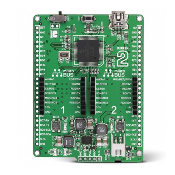
The mikroBUS™ connector consists of two 1x8 female headers with SPI, I 2C, UART, RST, PWM, Analog and Interrupt lines as well as 3.3V, 5V and GND power lines. Clicker 2 for CEC1702 for CEC1702 board can be powered over a USB cable. Page 4 Arrow.com. -
Page 5: Key Features
4.7µF GPIO204 GPIO051 XTAL GPIO204/ADC04 gpio XTAL1 VSS_ADC TS5A3357 XTAL2 VSS_ANALOG 32.768kHz 1µF 10pF 10pF 0.1µF 22µF VTR_PLL clicker 2 for CEC1702 schematic Page 5 Arrow.com. Arrow.com. Arrow.com. Arrow.com. Arrow.com. Downloaded from Downloaded from Downloaded from Downloaded from Downloaded from... - Page 6 VCC-5V VCC-5V 2.2µH VCC-USB VCC-USB LDO3V3 10pF 22µF 1µF 88.7k 10000pF 22µF 10µF 16.9k VSYS clicker 2 for CEC1702 schematic Page 6 Arrow.com. Arrow.com. Arrow.com. Arrow.com. Arrow.com. Arrow.com. Downloaded from Downloaded from Downloaded from Downloaded from Downloaded from Downloaded from...
-
Page 7: Power Supply
1. Power supply USB power supply You can supply power to the board with a Mini USB cable provided in the package. On-board voltage regulators provide the appropriate voltage levels to each component on the board. Power LED (GREEN) will indicate the presence of power supply. - Page 8 VCC-BAT VCC-BAT VCC-BAT VCC-BAT VCC-3.3V GPIO040 LED GREEN DMP2305U-7 10µF SHM1x2 VCC-3.3V 100k GPIO204 100k 100k 0.1µF VCC-3.3V VCC-3.3V VCC-3.3V LDO3V3 LDO3V3 LDO3V3 22µF 1µF 10000pF 1µF LDO3V3 2.2k GPIO026 DMP2305U-7 VSYS VSYS VSYS PWR-EN 3.3k 0.1µF LTC3586EUFE 2.2µF 2.2µF 1µF JS202011AQN VCC-BAT...
-
Page 9: Cec1702 Microcontroller
2. CEC1702 microcontroller The clicker 2 for CEC1702 development board comes with the CEC1702 microcontroller from Microchip. The CEC1702 is a full-featured ARM® Cortex®-M4-based microcontroller with a complete hardware cryptography- enabled solution in a single package. This low-power but powerful, programmable 32-bit microcontroller offers easy-... -
Page 10: Programming The Microcontroller
3. Programming the microcontroller Figure 3-1: CEC1702 microcontroller The microcontroller can be programmed in three ways: Using USB HID mikroBootloader, Using external mikroProg for CEC1702 programmer ™ Page 10 Arrow.com. Arrow.com. Arrow.com. Arrow.com. Arrow.com. Arrow.com. Arrow.com. Arrow.com. Arrow.com. Arrow.com. Downloaded from Downloaded from Downloaded from Downloaded from... -
Page 11: Programming With Mikroprog ™ Programmer
3.1 Programming with mikroProg programmer ™ On-board mikroProg™ programmer requires special programming software called mikroProg Suite™ for ARM®. This software is used for programming of all supported microcontroller families with ARM® Cortex™-M3 and Cortex™-M4 cores. The software has an intuitive interface and SingleClick™... -
Page 12: Mikroprog Suite For Arm Software
mikroProg Suite for ARM software ™ ® On-board mikroProg programmer requires special programming software called mikroProg Suite ™ ™ for ARM . This software is used for programming of all supported microcontroller families with ® Cortex -M3 and Cortex -M4 cores. The software has an intuitive interface and SingleClick ®... - Page 13 VCC-3.3V JTAG_TMS* JTAG_TCK* JTAG_TDO* JTAG_TDI* VCC_RST* SHD_CS0* VCC-1.8V VCC-3.3V NVT2006BQ VCC_RST* VREFB VREFA JTAG_TMS* JTAG_TMS JTAG_TCK* JTAG_TCK JTAG_TDO* JTAG_TDO JTAG_TDI* JTAG_TDI VCC_RST NVT2006BQ 2N7002ET1G VREFB VREFA SHD_CS0* SHD_CS0 JTAG_TDO* SHD_MISO JTAG_TCK* SHD_SCK JTAG_TMS* SHD_MOSI NOTE Before attaching the programming VCC-1.8V connector, you VCC-1.8V VCC-1.8V...
-
Page 14: Buttons And Leds
Figure 4-1: 4. Buttons and LEDs Two LEDs, two buttons and a reset button reset button The board also contains a and a pair of buttons and LEDs, as well as an ON/OFF switch. The Reset button is used to manually reset the microcontroller—... - Page 15 VCC-3.3V VCC-3.3V LDO3V3 VCC-3.3V VCC-3.3V VCC-3.3V VCC-3.3V LDO3V3 VCC-3.3V VCC-3.3V 0.1µF 0.1µF 0.1µF 0.1µF 0.1µF 0.1µF 100k VCC_RST VTR2 VTR2 CEC1702-84 PS2 Interface GPIO INT1 INT0 GPIO112/KSO05 GPIO030/TIN3/KSI5 GPIO113 INT3 VCC-3.3V GPIO113/KSO06 GPIO027/TIN2/KSI4 GPIO026 GPIO026/TIN1/KSI3 GPIO021 JTAG GPIO021/KSI2 GPIO120 GPIO120/KSO07 100k JTAG_TCK GPIO107...
-
Page 16: Power Management And Battery Charger
5. Power management and battery charger clicker 2 for CEC1702 features LTC®3586-2, a highly integrated power management and battery charger IC that includes a current limited switching PowerPath manager. LTC®3586 also enables battery charging over a USB connection. Figure 5-2: power... -
Page 17: Oscillators
6. Oscillator The CEC1702 microcontroller is equipped with an internal 32kHZ oscillator that provides a stable clock signal. The board also contains a 32kHZ crystal oscillator. Page 17 Arrow.com. Arrow.com. Arrow.com. Arrow.com. Arrow.com. Arrow.com. Arrow.com. Arrow.com. Arrow.com. Arrow.com. Arrow.com. Arrow.com. Arrow.com. - Page 18 VCC-3.3V VCC-3.3V LDO3V3 VCC-3.3V VCC-3.3V VCC-3.3V VCC-3.3V LDO3V3 VCC-3.3V VCC-3.3V 0.1µF 0.1µF 100k 0.1µF 0.1µF 0.1µF 0.1µF VCC_RST CEC1702-84 PS2 Interface GPIO INT1 INT0 GPIO112/KSO05 GPIO030/TIN3/KSI5 GPIO113 INT3 VCC-3.3V GPIO113/KSO06 GPIO027/TIN2/KSI4 GPIO026 GPIO026/TIN1/KSI3 GPIO021 JTAG GPIO021/KSI2 GPIO120 GPIO120/KSO07 100k JTAG_TCK GPIO107 GPIO147/I2C08_SDA/JTAG_CLK GPIO107/KSO04...
-
Page 19: Usb Connection
7. USB connection Connection with target USB host is done over a mikro USB connector which is positioned next to the battery connector. Figure 7-1: Connecting USB cable to clicker 2 Page 19 Arrow.com. Arrow.com. Arrow.com. Arrow.com. Arrow.com. Arrow.com. Arrow.com. - Page 20 VCC-USB 8.2k GPIO225 VBUS USB-D_N USB-D_P 4.7k 10000pF USB MICRO VCC-3.3V VCC-3.3V GPIO171 2.2k 4.7k FT230x VCCIO GPIO170 GND PAD GPIO135 0.1µF Figure 7-2: USB module connection schematic Page 20 Arrow.com. Arrow.com. Arrow.com. Arrow.com. Arrow.com. Arrow.com. Arrow.com. Arrow.com. Arrow.com. Arrow.com. Arrow.com.
-
Page 21: Pads
Figure 8-1: Connecting pads schematic Pads HDR1 Most microcontroller pins are available for further connectivity via two 1x26 rows of connection pads on both sides of the clicker 2 for CEC1702 board. They are designed to match additional Page 21 Arrow.com. -
Page 22: Pinout
9. Pinout VSYS System power supply Reset pin Reference Ground Reference Ground P200 P201 P202 P053 Analog Lines P203 P054 P107 P001 PWM lines P002 P140 P134 P120 P165 P030 P050 P112 Interrupt Lines P017 P013 P027 PO47 Digital I/O lines P020 P012 P162... -
Page 23: Mikrobus Pinout
™ Having two mikroBUS sockets and an additional connection pad, clicker 2 for CEC1702 utilizes all of the CEC1702’s I/Os. Each of ™ the two UART outputs has its own separate connection pin (either on mikroBUS 1 or 2, or on the 2x26 connection pad). Of the ™... -
Page 24: Click ™ Boards Are Plug And Play
10. click boards are plug and play! ™ Up to now, MikroElektronika has released more than 270 mikroBUS ™ compatible click boards. On the ™ average, two click boards is released per week. It is our intention to provide you with as many add-on... - Page 25 RFid click Relay click 8x8 click FM click Bluetooth2 click Thunder click ™ ™ ™ ™ ™ ™ USB SPI click ™ BarGraph click 7seg click THERMO click Gyro click EEPROM click LightHz click Pressure click ™ ™ ™ ™ ™...
-
Page 26: Dimensions
11. Dimensions Page 26 Arrow.com. Arrow.com. Arrow.com. Arrow.com. Arrow.com. Arrow.com. Arrow.com. Arrow.com. Arrow.com. Arrow.com. Arrow.com. Arrow.com. Arrow.com. Arrow.com. Arrow.com. Arrow.com. Arrow.com. Arrow.com. Arrow.com. Arrow.com. Arrow.com. Arrow.com. Arrow.com. Arrow.com. Arrow.com. Arrow.com. Downloaded from Downloaded from Downloaded from Downloaded from Downloaded from Downloaded from Downloaded from Downloaded from... - Page 27 No part of this manual, including product and software described herein, may be reproduced, stored in a retrieval system, translated or transmitted in any form or by any means, without the prior written permission of MikroElektronika. The manual PDF edition can be printed for private or local use, but not for distribution.
- Page 28 If you want to learn more about our products, please visit our web site at www.mikroe.com If you are experiencing some problems with any of our products or just need additional information, please place your ticket at helpdesk.mikroe.com If you have any questions, comments or business proposals, do not hesitate to contact us at office@mikroe.com Page 28...
Need help?
Do you have a question about the CLICKER 2 and is the answer not in the manual?
Questions and answers